Chapter 3. Material Mechanics
Designers worry their designs will break. We must have a deep, intuitive sense for the behavior of materials so that among the flourishing ideation, we don’t end up with designs that can never work in the real world. Therefore, we need to understand the behavior of solid objects when a load is applied so we know whether it will break or bend to the point where it can’t do its job. Designers also need to understand how shape affects the rigidity of an object, how much it will bend or twist when it is being used. While the theory of material mechanics must not intrude on the creative process, it must hold a place in refining ideas so products are not designed to break. While Louis Sullivan’s aphorism that “form should follow function” is not always true, there exists design chauvinism when designs flaunt the laws of nature. Flaunting of nature can be appealing, sometimes suggesting motion and instability. It can have artistic merit. The goal of this section is to understand material behavior so we have a sense for how our designs will work in real-world applications. Like the fine arts, the designer should sit in the driver’s seat and not just hope an engineer will rescue your design from failure.
We want to understand how a solid object responds to being used. We will look at the relationship between stress and an object’s shape as well as sneaky things such as fatigue fractures, buckling, and thermal expansion. These insights will allow you to synthesize these concerns while in the early stages of design and creative exploration.
Tools
This chapter considers solid materials, but we will look later at liquids and gases. While this theory should inform your design, this reading must be coupled with experimentation. You want more than a technical vocabulary and scientific certitude. You need to break stuff. You need to bend and twist things—all sorts of things. Grab some rulers, pencils, soda straws, and paper clips and mess around.
The Effects of Pulling, Pushing, and Twisting Forces
Solid objects move when a force is applied to them. If they are constrained, they may not move in some way you can see. However, they will get squeezed or stretched internally. The force generates internal stresses that can cause the material to break. The way an object moves internally is the key to understanding a material’s behavior under load.
Every type of material has a unique way of stretching or compressing. Some materials are viscous, like a fluid; others are elastic, like a solid. Some materials fall in between, such as plastic and blood. They flow like a liquid yet can be stretched and recover to their original dimension like a solid. These materials are called viscoelastic and will be discussed in Chapter 6. The relationship between the force produced by a load and the movement of the material defines how it can be used.
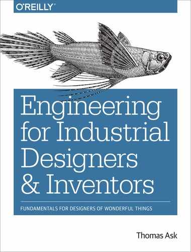
Although a force can only produce tension, compression, and shear, it is convenient to think of loads being applied to an object in five ways:
-
Tension
-
Compression
-
Shear
-
Torsion
-
Flexure
Tension is simply a force that pulls apart an object’s molecules, while compression is the opposite of tension and is the squeezing of an object’s molecules. Most materials have a higher compressive strength than tensile strength.
Shear is a set of opposing forces in the same plane. For example, if the bottom of a plate is rigidly attached to a surface and then the top of the plate is pushed parallel to the surface, a shear force will be applied to the plate. The shear force occurs when the force at the bottom of the plate resists the force on top of the plate. These opposing forces are transmitted as a shear force in the plate. If the plate were made from a stack of papers, the shear force would readily allow the papers to slide across one another. The ability to bear a shearing stress is the feature that defines solids. Solids resist shearing forces while fluids (gases and liquids) will flow until the shearing stresses are gone.
Torsion is a twisting force. For example, a rod that is held rigid at one end while a rotating force is applied at the other end will experience a torsional force on the rod. The outer surface has the highest stress and the centerline will have zero stress. The behavior of a design can be very different when subject to torsional loads as opposed to flexural or other loads. It is for this reason cross bracing is used in many structures. For example, a box-shaped structure like a bookshelf can have its torsional deflection reduced 100 fold by including cross bracing. Simpler diagonal bracing is also very effective, but this design generally permits three times more deflection than cross bracing. Torsional rigidity can also be improved by incorporating closed members such as tubing rather than open members such as U channels.
Torsion is important to understand in a variety of applications, such as the bookshelf previously mentioned, but also propulsion systems where all the power is transmitted by torque. Not only can this torque tear apart shafts but it can produce torsional vibrations that need to be stopped by changing material properties or with dampeners. Helmets must be designed for more than impact loading; they must reduce the twisting of the head. This can be done with membranes that allow a sliding action to occur between the shell and the head.
Flexure is a load that does not fall in line with the central axis of a part, like standing at the end of a diving board. This is an extremely common loading condition and is produced by an offset load that creates tensile loading in one half of a part and compressive loading in another half. If a bar is supported at both ends and a load is applied in the center, the material on the same side of the centerline as the load will be in compression whereas the material on the opposite side of the load will be in tension. In addition, the stress varies with the distance from the centerline. Flexural stress is harder to understand than the other stresses because it is a function of a part’s shape. For example, an I-beam is much stronger in one plane than an equivalent mass of square steel. This will be considered in more detail later.
Tension, compression, shear, torsion, and flexure—now get a paper clip, stick, or a ruler and try them all out. Pull, push, shear, twist, and bend and see how it behaves. Notice the ruler twists pretty easy. It is rigid in one axis but it can easily be twisted and bent in other axes. Now try twisting a pen. It is torsionally rigid. What appear to be strong objects can be very weak in some stress conditions. You can park a car on a pile of papers, but they are easy to shear or pull apart. While this will all be good fun, you will need some squishy clay to really see the effect of compression. Figure 3-1 shows a summary of these loading conditions.
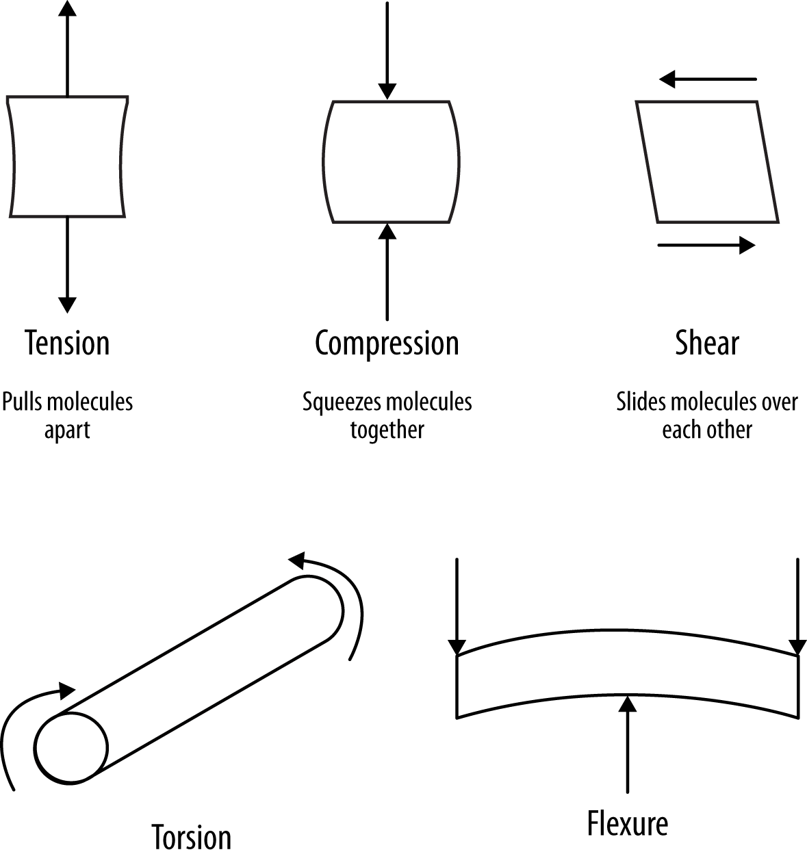
Figure 3-1. Common loading conditions; these create tensile and/or compressive stresses
Why does a designer care about this? Because only you know what loads might be applied to your design and you must understand the stresses these loads will produce. We will discuss later how the shape of your design will dictate the intensity of these stresses and therefore how strong and rigid your design is. These terms have different meanings: strong means your design won’t easily break; rigid means it won’t easily deform.
Static Loads
When considering the behavior of a design, we typically start with evaluating how loads and twisting action are transmitted through an object. Loads move objects. Either they accelerate and move or they make small internal movements called strain. If you are sitting on a teeter-totter with someone of equal weight on the other side, the teeter-totter is balanced in a state of equilibrium. If you push up with your legs, that force propels you up and the other person down until they push back on the ground. If you extend a ruler over the edge of a desk and push down on it, you can feel the load in the hand holding the other end. If you push down further from the edge of the ruler, the resisting force you have to apply increases. The reaction to a force and a distance is called a moment. Moment is also referred to as a couple or torque. Equilibrium requires that the summation of all forces and moments on an object be equal to zero. This study of how forces transmit through a stationary object is called statics.
The term load can be used loosely—when we stand on a floor, we are putting a load on it. However, the term describes two things: force and direction. In the case of the floor, the force is your body weight and the direction is down in line with gravity. The loads and moments upon which an object is subject depend on both the magnitude of the load and its distance from a support. For example, the deflection of an overhung (cantilever) beam is sixteen times that of a beam simply supported at both ends. You can experiment with a ruler and different supports to get a real sense for this behavior. This perception of loads is intuitive for us because our limbs are a bunch of beams that are usually cantilevered. We know it is hard to hold something far from our body. We prefer our limbs to be supported at both ends, hence we like to put our elbows on the table while we are eating (a fork full of food is heavy!) so at least our upper arms are supported at both ends.
When a force is applied to an object, it follows Newton’s three laws of motion. The first two relate to dynamics. The first law is that every object in a state of uniform motion tends to remain in that state of motion unless an external force is applied. This corresponds to the inertia of an object. Inertia is a property of matter and matter does not want to accelerate or decelerate on its own—it needs a force to make that happen.
Newton’s second law states that force is equal to mass times acceleration. Therefore, it takes force to accelerate a mass. The higher the mass or the higher the desired acceleration, the greater the required force. If you put a model rocket engine on a car, nothing interesting will happen, but if you put the same engine on a much less massive model rocket—wow!
Newton’s third law brings us right back to where we started with regards to statics. The third law states that for every action there is an equal and opposite reaction. When you stand on a bridge, the bridge is pushing up on you with the same force. You will have noticed this if you try stepping off a canoe. When you push off the canoe, the canoe can’t push back very well because it has low inertia and is floating on water so it gets pushed away from you.
Identifying all the forces with which an object must contend is necessary in evaluating a design. Some of these might not be obvious, such as the mechanic who uses a filter bracket as a footstep to service a turbocharger. The second biggest load this bracket would encounter is when the engine is being transported by rail and the cars smash into each other during latching. Think about the damage caused by the expansive force of ice in roads, or bird droppings on a car. Toyota recently recalled more than 800,000 cars because of the potential for a spider web to block the condensate drainage of the air conditioner and damage the air bag electronics.
Many forces in nature are trying to destroy your design in a beautifully natural way. The design world is full of these unanticipated usages and they must all be considered. Toy designers probably have the biggest challenge in this area—kids do amazing things!
Draw upon your creative insights, and think about how the object could be misused and what this might do to the object. Are screwdrivers only used to drive in screws? Of course not! Figures 3-2 and 3-3 show examples of misuse.

Figure 3-2. If you design doorknobs, doors, or door hinges you need to know about this traditional application

Figure 3-3. Garbage cans are not just for garbage; they are great places to rest a box. How heavy a box should it hold?
Forces are normally sketched out on free body diagrams, such as shown in Figure 3-4 and Figure 3-5.
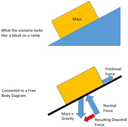
Figure 3-4. Free body diagram

Figure 3-5. Forces diagram of a car
This diagram indicates the load, direction, and type of force. Remember to consider the loads, temperatures, and other environments encountered during shipping, handling, and expected misusage as previously described.
Mechanics of Deformable Bodies
In addition to the reaction of an object to a load, another important characteristic of a material is its behavior as it is about to break. Designers care about how their products will stretch and deform because we understand the weak points and vulnerabilities of a product more than anyone else. Some materials, like glass, are brittle and hardly stretch before they break. Other materials, like wood, are ductile and stretch noticeably before they break. This ductility characteristic determines the existence of common warning signs (bending or stretching) prior to imminent failure. The category of deformable bodies includes all solids because they can develop internal stresses. The behavior of fluids will be described in Chapter 6.
A force’s effect on a material is dependent on the size of the area upon which the force is applied. The force per area is called stress and is simply equal to force divided by area:
σ = F/A
where:
σ = stress
F = force
A = area
Strain is the same as stretch but refers specifically to the movement per unit length. Stress-strain diagrams have been developed for most materials by taking a sample of the material and applying force while monitoring its length. The force is continuously increased until the sample breaks.
Most materials you encounter are elastic. That is, over a certain range of stresses the strain is directly proportional to the stress (Hooke’s law). Moreover, when the stress is removed, the materials return to their original unstressed dimensions. Flexing of a material can be part of a compliant mechanism such as with springs and paper clips.
Both rubber bands and steel rods act like an elastic material. If supporting the same weight over the same cross-sectional area, a rubber band will stretch much more than steel. This difference in stretch is described by the slope of the stress-strain line and is called the modulus of elasticity (or Young’s modulus) and is equal to the difference in stress divided by the difference in strain:
E = σ/ε
where:
E = modulus of elasticity
σ = stress
ε = strain
The unit for force is pound (lb) or Newton (N) in SI units. The units for stress are pounds per square inch (psi) or Pascal (Pa) in SI units. One Pascal equals one N/m2. The conversion is: 1 psi = 6,895 Pa. Strain is measured in length per original length—this gives a strange unit of in./in. or mm/mm. Because the modulus of elasticity is stress divided by this unit canceling strain, the modulus of elasticity becomes psi or Pa. Table 3-1 shows the relationship between stress and strain for different materials before they break or permanently stretch.
| Material | x 1,000,000 psi | GPa |
|---|---|---|
Osmium |
80 |
552 |
Steel |
30 |
206 |
Brass |
16 |
110 |
Aluminum |
10 |
69 |
Concrete |
3 |
9.2 |
Wood |
1.5 |
4.6 |
Polyethylene |
0.014 to 0.18 |
0.096 to 1.24 |
Rubber |
0.0006 to 0.50 |
0.004 to 3.4 |
What happens to a material as the stress is continually increased? The yield strength (or elastic limit) is reached, beyond which the material continues to stretch but will not completely recover if the stress is removed. This permanent stretching (called yielding or plastic strain) at stresses above the elastic limit occurs in what is called the plastic region. As the stress is further increased, the material finally breaks at a load called the ultimate strength. Figure 3-6 shows the relationship between stress and strain for ductile and brittle materials.
Where does the material for the stretching come from? In the elastic region, the stretching comes from the increased distance between atoms. In the plastic region, groups of atoms (crystals or grains) slip or deform to allow the stretch. As the material strains in one axis, it also strains in the perpendicular axes. This intuitive relationship is denoted by the ratio of strains called the Poisson’s ratio.

Figure 3-6. Stress-strain diagrams for ductile and brittle materials
Consider these practical implications of the relationship between stress and strain:
-
Usually the most important stress level to consider is the yield strength rather than the ultimate strength. That is, all considerations of safety factors, fatigue strength, and impact loading are based on a value that will allow the material to completely recover from the applied stress. Notable exceptions are body armor and crash cushions where the energy of the impact is absorbed by taking the material up to or beyond its ultimate strength.
-
The modulus of elasticity determines the flexibility of a material and is independent of its strength. However, an object’s size and shape is the most important determinant of its flexibility. For example, a thin stick blows readily in the wind whereas a thick trunk made of the same wood does not move at all. The relationship between shape and rigidity is presented in more detail later.
-
The area under the stress-strain curve indicates a material’s toughness or energy absorption ability. The larger the area, the more energy the material can absorb before it breaks. For example, plastic may be weaker than ceramics but it is tougher.
-
Unlike metals, typical composites like wood, fiberglass, and carbon fiber do not have the same stress-strain characteristics in all axes (known as anisotropic); therefore, the modulus of elasticity and yield strength will be different depending on orientation. If a load is pulling in the same direction as the fiber orientation, it will be much stiffer and stronger than if it is pulling perpendicular to their orientation. With a perpendicular load, the fiber strength is unused and only the bonding material (such as epoxy) offers resistance to the load. Metals are isotropic materials and have the same stress-strain relationships in all axes.
Shape
Before considering how an object’s shape affects its strength and rigidity, let’s recall that forces produce some combination of tension or compression. However, it is helpful to consider forces present in five different categories. As described previously, these are tension, compression, shear, flexural, or torsional loads.
Shear loading is sliding force whereby the molecules are being asked to slide against each other as opposed to being pulled apart as with tension or squeezed as with compression. In the case of fluids, the shear resistance is very low so it flows easily. The stresses produced by tension, compression, and shear are the easiest loads to calculate because they are simply calculated as force divided by cross-sectional area. Therefore, increasing the area of something, say using a 1/2-inch (12 mm) bolt instead of a 1/4-inch (6 mm) bolt, decreases the stress. Thick is good (but heavy).
Relationship Between Shape, Stiffness, and Flexural Stress
Strength and stiffness come from two different features. Strength is a property of a material while stiffness is a property of the shape of the material. A piece of sheet metal is strong enough to withstand a high level of stress before breaking, yet it easily flexes and buckles. To stiffen the assembly, the sheet metal could be layered upon each other to produce a thicker assembly. This thick assembly of sheets of metal would be rigid and strong but heavy and expensive.
In metal and wood construction, the sheets are stiffened with a framework. In fiber-reinforced plastic (FRP) sandwich construction, an assembly combines a thick layer of low-density material (e.g., foam or honeycomb material) bonded between an inner and outer FRP laminate. The resulting sandwich composite is lighter, less costly, and nearly as strong and as rigid as an equally thick laminate.
Relationship Between Stress and Thickness
Corrugated cardboard is amazing material. Stiff, strong, and lightweight. This cardboard construction demonstrates an example of sandwich construction. This corrugated cardboard is made entirely of paper with a wavy (corrugated) section of paper sandwiched between the outer layers of flat cardboard. The corrugated cardboard is made rigid because the corrugations separate the flat cardboard, which does not stretch easily, away from the neutral axis. Imagine how floppy the cardboard would be if the corrugated section was flattened out and all the paper layers were laid on top of each other. Even if the flattened paper were replaced by thin sheet metal, it would still not be as rigid as the corrugated form. This increased rigidity and strength are only apparent when the composite is bent. In pure tension, it has virtually no effect—that is, the flattened paper would be as rigid as the corrugated paper if it were pulled at the ends. Figure 3-7 shows a relationship between thickness and stress.
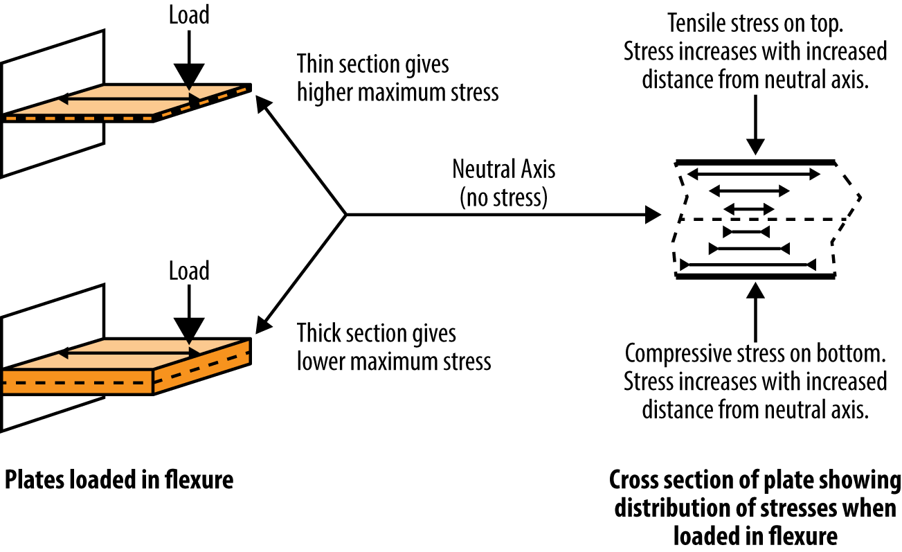
Figure 3-7. The relationship between thickness and internal stress
The relationship between rigidity and shape is described and quantified by the moment of inertia. Moment of inertia is specifically related to the shape of the cross section under load. In the case of flexural loading (a load that produces only a moment, not an axial or torsional force), the stress produced in the part is inversely proportional to the moment of inertia:
where:
σ = flexural stress
M = moment on section equal to the force times distance
c = distance from neutral axis (usually, the only value of concern is the maximum c value, which is half the thickness of the section)
I = moment of inertia
The higher the moment of inertia, the lower the stress produced under a given load. If a part is designed so the material is far away from its center, or neutral axis, it will have a higher moment of inertia than if all the material is bunched up around the center. In fact, the moment of inertia increases as a cubic function of the thickness. Figure 3-8 shows how a beam can be made 75% more rigid by changing its shape.

Figure 3-8. By changing the shape of the rectangular beam to that of an I-beam, the rigidity increases by over 75%, yet the weight is unchanged, however, this is only true in the vertical plane; in the horizontal plane, the I-Beam is 250% less rigid than in the vertical plane; this illustrates that if the direction of loading can be predicted, it is very beneficial to develop a shape that puts as much of the material as far as possible from the neutral axis
For a rectangular cross section, the formula for I is:
where:
b = width of the section
h = thickness (or depth) of section
For a solid rod cross section, the formula for I is:
I = π r4/4
where:
r = radius of rod
A tube has a much higher moment of inertia than a solid rod of the same mass because the mass of the tube is located further from the center. Figure 3-9 shows two round shapes that have the same rigidity even though the tube is almost one half the weight of the rod. Unlike a tube, an I-beam is optimized for resisting bending in one plane. Therefore, a load must be positioned in a way that takes advantage of its shape.
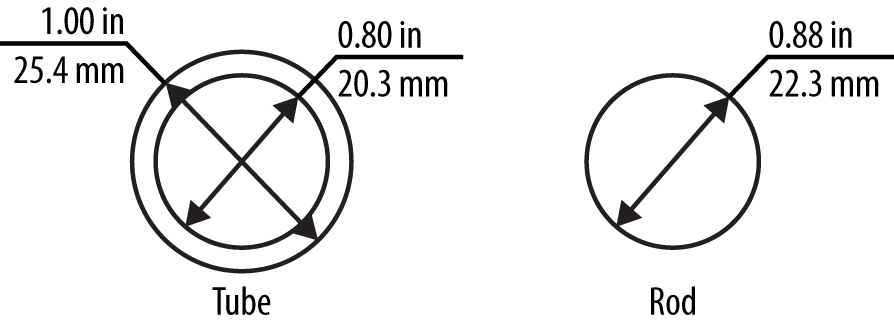
Figure 3-9. Tube versus solid rod
Section modulus is often used to describe the properties of a structural shape when dealing with structural steel. Section modulus is equal to the moment of inertia divided by the distance from the center of the shape to its furthest edge (c), such as the radius (r) or half the height (h) in the case of a rectangular shape:
Section modulus (S) = I/c
Torsion has a similar relationship except the design’s polar moment of inertia—that is, the shape from a twisting perspective—dictates the torsional shear stress. For example, a large-diameter pipe with a thin wall will have a higher polar moment of inertia than will a small-diameter pipe with a thick wall. Torsional shear stress (τ) is equal to the torque (T) times the distance from neutral axis to outer fiber (r) divided by the polar moment of inertia (J):
τ = T r/J
where:
τ = torsional shear
T = torque
r = radius from neutral axis to outer fiber
J = polar moment of πR4/2
Few items are under pure tension, compression, or shear. Some items, such as bolts, are designed to be under pure tension and shear only, but these are the exception. Consequently, understanding flexural behavior is essential for predicting potential failures.
Flexural behavior does not consider another phenomenon that will make parts fail at stresses well below their yield stress. This phenomenon is called buckling and is a common failure mechanism for long, slender objects. Buckling behavior, a well-understood phenomenon, is carefully considered in design calculations.
Stress Concentration
If you want to know where your design is most likely to break, look for sharp corners and notches. A sudden change in an object’s form, such as a sharp corner, notch, hole, or crack, will result in an increase in stress called a stress concentration. These geometric changes tend to squeeze (concentrate!) stresses into a smaller area, as shown in Figure 3-10. Stress concentrations also arise around microscopic fissures, which can lead to fatigue failure that will be described later. The mathematical analyses of stress concentrations are so complex that their amplifying values are obtained experimentally.

Figure 3-10. Stress concentration shown in sharp corner of flexed protractor by photoelastic visualization
Figure 3-11 shows a graph of stress concentration versus radius sharpness. This relationship between shape and stress concentration illustrates the importance of gradually bending mating surfaces. Cracks concentrate stresses.
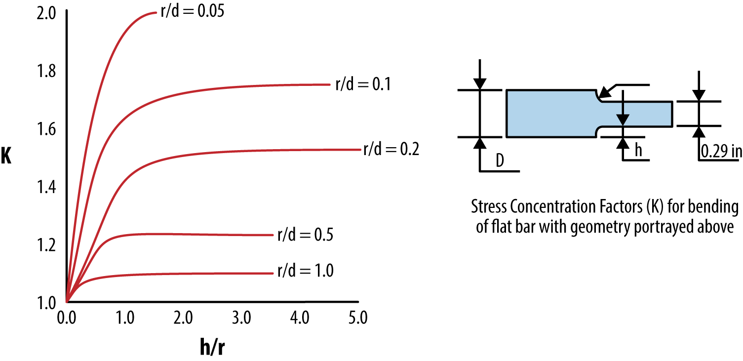
Figure 3-11. Stress concentration versus radius sharpness
Stress concentration effects are reduced by moving the abrupt change of form to a lesser stressed section of the object. The problem of stress concentrations has long been known, and boat builders would seek trees with natural fillets for use in highly loaded sections such as keels and mast connections. These valuable forms are stockpiled, as shown in Figure 3-12.

Figure 3-12. Wooden sections saved for highly loaded features in boat construction
In building construction, holes are drilled in the center of beams where very low stress exists (see the section “Relationship Between Shape, Stiffness, and Flexural Stress”) and away from the area of maximum moment. It is accepted practice in some applications to drill small holes at each end of a crack to reduce the stress concentration in this area and to stop the crack’s progress.
Ductile materials are less sensitive to stress concentrations than brittle materials because they deform when loaded. This reshaping redistributes the load over a broader area. Even though the brittle form of a material can often handle higher stresses, a ductile material can distribute stress and therefore actually handle a higher load.
Fatigue
As a material is continually loaded and unloaded, its maximum strength decreases. This gradual weakening is called fatigue, a name derived from an early misunderstanding of this phenomenon. The metal was thought to have become “tired” over time. Fatigue is now understood to be caused by movements within the material that cause cracks to propagate through the material’s grain boundaries. One solution to fatigue failure is to over-design an object—that is, use massive thicknesses to ensure longevity. However, understanding the rate of decline of a material’s strength is a more environmentally and cost-sensitive solution. Generally, if the stresses experienced by an object under cyclic tension and compression loading are less than one-half of the yield stress, the object will never fail due to fatigue. Therefore, highly efficient designs are produced only when the anticipated loading and fatigue characteristics are fully understood.
Fatigue failures often start at a stress concentration or at the surface of an object, where stresses are highest. Small surface cracks may be the first sign of fatigue. However, there may be no visible cracking because the cracks may be too small to see, start from inside the object, or be obscured. For example, the stress concentration at the corner of a notch in a shaft (such as the keyway) is a common location for fatigue cracking but this area cannot be observed unless the shafted assembly is completely torn apart.
Inspecting a broken object that is subject to fatigue failure will always show two different surface characteristics:
-
The fatigue zone where cracks slowly propagated into the object
-
The instantaneous zone where the crack accelerated quickly through the object
The relationship between the size of the fatigue zone and the instantaneous zone indicates the relative loading of an object. The instantaneous zone is produced when the effective area (total area minus fatigue zone) is too small to support a load. Therefore, if the instantaneous zone is small, the object was not heavily loaded. However, if the instantaneous zone is large, the object was heavily loaded.
The fatigue zone is identified by beachmarks, which are small ridges on the broken surface of a material. These beachmarks are produced by the crack propagation. They in turn plot the crack progression. Due to abrasion within the crack, older fatigue zone areas are smoother than new ones and can help identify the failure origin.
Fatigue Strength
Fatigue strength describes the highest stress a material can handle for a specified number of cycles. Typically, if you want to have a part last an infinite number of stress cycles, the fatigue strength is half the yield strength. That is, an object that will be vibrating or encounter many loading cycles should only be designed to handle half the stress of an object that does not encounter many stress cycles. Simply put, if something experiences a lot of stress cycles, make it twice as thick (which is one way to double the moment of inertia). Again, this is a simplified statement. The actual calculation for required moment of inertia is more complicated.
Although fatigue strength is not directly related to any other material property, it is most closely related to tensile strength. Corrosion, galling, and other surface defects reduce a material’s resistance to fatigue more than can be associated with stress concentrations alone. Consequently, fatigue strength is usually determined experimentally. The fatigue properties of a material are based on testing specimens at different stress levels (S) and measuring the number of cycles to failure (N) to produce an S-N curve. Because real objects do not behave like test specimens, the design strength of a part is reduced based on:
-
Whether the part is subject to flexural or axial loading
-
The part size
-
Surface condition (e.g., polished versus forged)
-
Operating temperature
-
Safety factor
Fretting Fatigue
Fretting fatigue is a special form of fatigue that is initiated by the small vibrations of parts that are pressed together. Vibrations of the parts cause surfaces to crack. These cracks produce stress concentrations that accelerate the fatigue of the parts. Fretting fatigue often occurs at pressed joints, which are not intended to move. It can be readily reduced in these cases by decreasing the clearance between the fastener and the through hole, or by using higher strength and correspondingly higher tightening torques. Impact loading may also result from oversize holes due to design or wear. Impact is undesirable because of the amplified stress it produces.
Creep and Thermal Relaxation
Creep describes the gradual stretching of a material under a load. Although it is most common in unreinforced plastics, it happens occasionally in metals also. Creep is due to slippage of a material’s grains along their boundaries. This generally is not a concern except with highly loaded plastics that require dimensional stability and materials subject to high temperature. Thermal relaxation describes creep that is accelerated by high temperature.
Both fatigue and creep occur at stresses lower than the yield strength of a material. This means, for example, a drive shaft can break under normal loads after many years of reliable service. Furthermore, there will be no indicators of incipient fatigue failure. Corrosion of any sort greatly decreases fatigue strength. In fact, a part that has had pitting corrosion machined off will have much higher fatigue strength, even with the loss of material, compared to the original part with the pitting.
Many objects are designed for an infinite number of cycles but this evaluation can only be done by an engineer and must be verified by testing. A preventive maintenance schedule of critical components must be offered to properly ensure their reliability.
Buckling
Like fatigue, buckling is a failure mechanism that occurs at loads well below the material design strength. The best way to observe the buckling phenomenon is to stand carefully on an aluminum can, which should support your weight. With your full weight on the can, have someone else use two rulers to bend the sides of the can in slightly and the can will buckle and crush rapidly.
Buckling is the collapse of a material under compression when the object bends and folds at loads that it would normally support (as we saw with the can). Buckling is a principle concern in axially loaded beams and thin-walled cylinders and is caused by the large increase in stress when a part is shifted slightly off center. Depending on the design of the part, this will make the part unstable and cause it to collapse. Buckling calculations can become quite complicated but they are a function of the slenderness ratio of a part. Long, slender objects will buckle under compressive loading, while short, stout ones will not. Figure 3-13 shows the types of compression failures associated with slenderness.
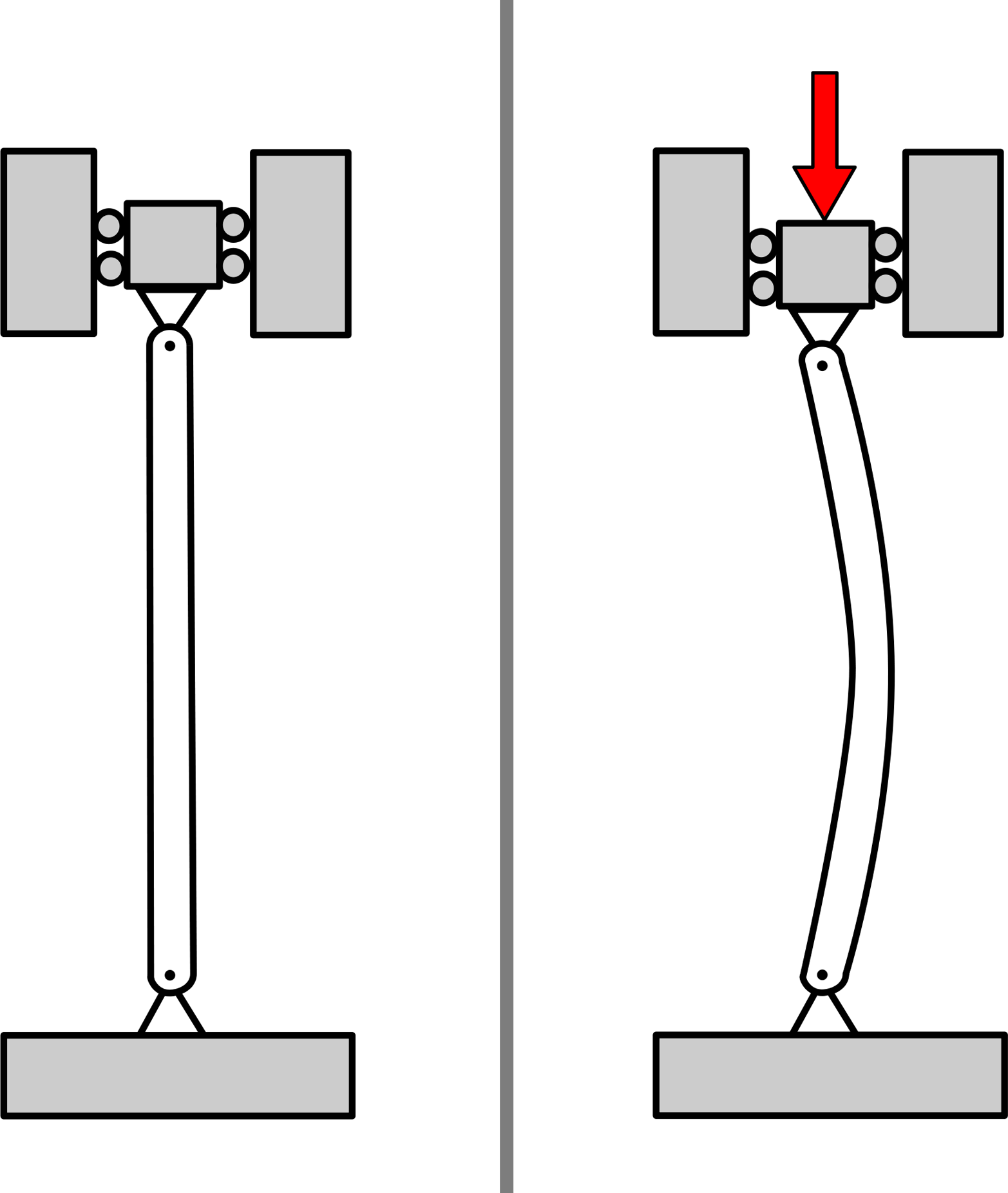
Figure 3-13. Long, slender objects fail (by buckling) at much lower loads than predicted by their yield stress
Warning
Don’t forget unexpected loads such as those associated with nature, shipping, and incorrect use!
Thermal Expansion
Hot stuff expands, cold stuff contracts. If an object is not allowed to move freely, it produces high stress as it grows into an adjoining object. Heat increases atomic vibration and makes the atoms act as if they are bigger. Therefore, thermal expansion and temperature are directly related. The amount of expansion varies by material and is measured by the thermal expansion coefficient. Brass has a thermal expansion that is 50% more than steel. Aluminum thermally expands at twice the rate of steel, as shown in Table 3-2.
| Material | Expansion coefficient (in./in./°F) | Expansion coefficient (mm/mm/°C) |
|---|---|---|
Steel |
0.000006 |
0.000011 |
Brass |
0.000009 |
0.000017 |
Aluminum |
0.000012 |
0.000022 |
Cast iron |
0.000005 |
0.000009 |
Polyethylenea (high density) |
0.000066 |
0.000119 |
Polycarbonatea |
0.000040 |
0.000072 |
Nylona |
0.000056 |
0.000101 |
Plate glass |
0.000005 |
0.000009 |
a Expansion coefficients for polyethylene, polycarbonate, and nylon (polyamide) vary widely based on specific composition | ||
Thermal expansion or contraction is calculated by:
ΔL = L1 α ΔT
where:
ΔL = change in length after heating or cooling
L1 = initial length
α = coefficient of thermal expansion
ΔT = temperature change
If two materials expand into each other, either because they have different thermal expansion coefficients or they are at widely different temperatures, they develop stresses directly related to the strain they produce. That is, the strain produces stress. If a column or pipe is anchored at both ends and is axially constrained, the compressive stress generated by thermal expansion becomes high. Plastics are viscoelastic, meaning they will flow like a liquid. Therefore, they can reduce the stresses caused by thermal expansion to some degree by fluid flow.
The compressive stress generated by thermal expansion is calculated by:
σ = α E ΔT
where:
σ = compressive stress
α = coefficient of thermal expansion
E = modulus of elasticity
ΔT = temperature change
We are designers, not vibrating molecule specialists, so why should we care about this? Thermal expansion can break things and change their shape. While you might think your product lives a benign life on a store shelf and in someone’s home, when it is shipped in the belly of an airplane or on a giant containership plying the north Pacific, it is exposed to freezing temperatures. When it is stored in an attic or transported by truck, it can get very hot.
The force of thermal expansion creates high stresses when two materials with dissimilar thermal expansions (e.g., plastic and metal or aluminum and steel) are entrapped. The stresses can also be produced when a hot object is completely constrained by another object, which is why bridges have thermal expansion joints. Thermal expansion is a special problem for big items or those that experience large temperature changes because the effect is multiplied. Therefore, such things as piping systems and engine exhaust need to be thermally accommodated by including flexible joints or bends to the system’s design.
Failure Modes
You have built a prototype and it broke. Now what? Well, there is a lot of good news in the broken parts you are looking at. They contain a wealth of data to help you see what went wrong. Even if your device doesn’t break, it is still considered “failed” if it stops working the way it should. This section describes different ways devices stop working, from breakage to changing their shape and jamming.
Elastic Deformation
This failure mode is caused by a load on a part high enough to distort the part to the point it will stop functioning. In other words, nothing breaks but the part shape changes so much under its load that it jams or locks up in some fashion. The load can be caused by an external force or thermal expansion. In the case of elastic deformation failure, the load distorts the material within its elastic range. That is, the stress induced by the load is low enough that the material recovers completely when the load is removed. If the stress is higher than the yield strength of the material, it will stretch and never recover. If the stress exceeds the ultimate strength of the material, the material will break.
Yielding
Yielding failure is similar to elastic deformation in that the part does not actually break. Unlike elastic deformation, the part will not return to its unstressed dimensions when the load is removed. Yielding occurs when the applied force exceeds a material’s yield strength. A part that has yielded is stretched, distorted, and is close to breaking. Ductile materials, such as steel, stretch a great deal before a ductile rupture occurs. Brittle materials, such as glass and fiberglass fiber, do not yield before a brittle fracture occurs. Consequently, ductile materials give warning signs before they break while brittle ones do not.
Ductile Rupture
Under a continually increasing load, a ductile material will elastically deform, yield, and then finally rupture. A ductile rupture is caused by the slow growth of internal cracks under a load. The cracks grow together until the part breaks. The fracture face will usually be rough and have a “torn out” appearance. This is due to the load shearing up and down between the grains.
Brittle Fracture
Unlike a ductile material, a brittle material has little yield and can fail without warning. A brittle fracture is caused by the rapid separation of interatomic bonds. The internal voids and cracks that are always present in materials initiate this fracture. In brittle materials, the stress concentrations produced by these features cannot be distributed. The fracture face of a brittle fracture will usually appear as a flat, crystalline surface and may show chevron-shaped beachmarks that point to the failure origin.
A brittle fracture can occur in normally ductile materials at low temperatures (below the transition or glass temperature) or when they have been subjected to stress corrosion cracking. When the temperature of a metal is below this transition temperature, a crack can travel faster than the metal can deform. Because deformation normally absorbs tremendous amounts of energy, a low-energy crack that does not produce deformation can propagate readily.
Fatigue
Fatigue is a failure mode caused by cyclic action of a part resulting in failure at a below-normal stress. This is by far the most common cause of mechanical failure. A fatigue fracture will show two distinctive surface appearances. One of these areas exhibits curved ridges or beachmarks that were produced as cracking slowly progressed through the object. The other surface will usually be rougher and show no distinct pattern. This rougher surface is created when the object is so weakened by the fatigue that it ruptures quickly.
Impact
Impact is a very rapidly applied load such as a hammer striking a nail. Stress waves, produced during impact, actually stack up on each other, amplifying the stress. Figure 3-14 shows an example of impact power.

Figure 3-14. Jackhammers amplify force by impact
Wear
Wear is the result of one object contacting another, leading to the removal of material. Wear is not necessarily due to the plowing of the object, specifically referred to as abrasive wear, but can also be due to adhesion of two mating materials. This adhesion causes surface cracks that grow and eventually cause small flakes of material to break away. This type of wear is called galling and if the wear continues, the galling will lead to seizure of the two wearing parts.
Cavitation is an erosive wear caused by the formation and implosion of bubbles. The shape of a flowing object, such as a propeller, can produce a pressure sufficiently low to boil a fluid. When the vapor recondenses, it implodes and wears material away.
Brinelling
Brinelling fractures occur when two curved surfaces are excessively loaded so yielding occurs over the small contact area. The most common example of brinelling is observed in ball bearings that have had an excessive radial load applied to them. This loading forces the balls against the inner part of the bearing (race) with sufficient force to brinell the surface and leave small dents in the race.
Noise and Vibration
Noise and vibration are important issues in design. They impact the health and experience of a user. Both noise and vibration are mechanical phenomena, whether they be oscillating air molecules or solid material. While noise can be harmful, its gentle cousins of music and sound can be reassuring, comforting, and an essential part of a user experience. Vibration can help us understand how something is responding, whether it be damaged bearings or an intentional haptic feedback system. However, vibration can also produce fatigue failure and other damage to mechanical systems.
Noise
Sound is one of the three senses, along with visual and tactile, to which the designer must appeal. (Yes, you could say four—who can deny the appeal of the smell of leather or jasmine?) Sound communicates. The zipping sound of a zipper tells us it is working, the snapping sound of a clip tells us it is engaged. The solid sound of a car door closing suggests quality. Sound is part of the designer’s palette that can inform and appeal to the user. Sound can often move from satisfying and reassuring to obnoxious noise. We get the squeaky shoe and the screaming vacuum cleaner. Unfortunately for the consumer, these sounds don’t become obvious until after purchase. Moreover, sounds are often more offensive to those who must listen as opposed to those who create the sound. It is more fun to hammer than to listen to a hammer. Noise is defined as an erratic order of various frequencies. Besides being bothersome, noise can have a physiological impact by producing hearing loss and physical stress.
Sound differences are measured in the logarithmic scale of decibels (dB). From the ticking of a wrist watch to the roar of a shotgun, the differences between the softest and loudest sound we can hear before eardrum rupture is a factor of many trillions.
However, it is not merely the loudness of the noise that is offensive. High frequencies are the most obnoxious and dangerous to humans. These obnoxious frequencies are captured in the weighted decibel scale (the standard unit for measuring sound). Weighted scales take the decibel readings in the frequency range of human hearing and heavily multiply the higher frequencies. The most popular weighted scale is the dBA scale. With this weighted scale, a sound that has a loud 10,000 Hz component would record a much higher dBA reading than does one with a loud 500 Hz component.
Acoustic resonance is the term used to describe the oscillation of an object at its natural frequency. When a tuning fork is struck, it will vibrate at a frequency dictated by its rigidity (moment of inertia) and material composition. Resonance is an important concept because the resonant frequency of parts near vibration sources should be designed to fall either at a very low frequency or at one well above the level of human hearing.
The best way to reduce noise is to locate its source and eliminate it at that point. For example, “engines” do not produce noise; it is certain components or features of the engine that produce the noise. Some of the root causes of engine noise are flowing inlet air and exhaust air, cylinder liners, gears, and shafts. These sources can be located by acoustic intensity measurements. Acoustic intensity measurements are made with a series of microphones and processing equipment that locate the exact position of a noise source.
The approach to noise abatement, excluding air flow noises for the moment, is to first identify the loudest noise source. The offending part may be temporarily replaced with a quieter material to verify it is the noise generator. Once verified, the object will be redesigned to reduce its noise. Often this involves changing its rigidity to move its natural frequency. This locating process is continued until the noise production is reduced as much as possible. After this is done, acoustic panels, mufflers and other more traditional noise abatement techniques can be used.
Basically, acoustic panels work by using the noise energy to vibrate foam. The soft foam does not transmit the noise well and thereby expends the noise energy and reduces further transmission. Acoustic panels are often made with a dense sheathing attached to the foam. This “tuned” system allows greater noise energy dissipation. Acoustic panels are often configured with a couple of stacked sheathed cores with the innermost sheathing made from a sheet of perforated metal.
Vibration
Vibration can be reduced by changing the rigidity or by vibration isolation. Rotating equipment is often mounted on flexible mounts that reduce the transmission of vibrations to the equipment.
Torsional vibrations are oscillatory movements arising in rotating equipment and can manifest themselves as gear chatter. A rotating shaft’s torsional rigidity, length, and the moment of inertia dictate the frequency at which the shaft oscillates back and forth. However, the shaft’s resonant frequency can be moved above the operating speed by stiffening the shaft or using a flexible coupling. Viscous dampers are sometimes mounted to the end of shafts to absorb minor torsional vibrations.
Closing Thoughts
Now for the juggling! You know the careful shaping of an object’s cross section lets you use the minimum amount of material and avoiding sharp corners reduces stress concentration. You know long, skinny shapes buckle, high loading cycles produce fatigue, impact amplifies stresses, corrosion can be hidden, and materials expand when they are heated. All of these factors go into keeping the loads under the yield stress of the materials.
If you were designing a water piping system, you would need to worry about many more things than simply its ability to move water from one place to another. You would think about what happens to the pipe when the water is turned off quickly (impact), what happens when it heats up (expands), and what happens at the elbows (stress concentration). You would also be thinking about the flexing of the pipe, the axial loading of the pipe supports, and the corrosion of fittings.
If you were designing a fancy new bicycle wheel, you would need to think about the load of the weighted bike traveling through the wheel, the impact of potholes, and the corrosion produced by water and road salt (not to mention what that will do to the bearings!) You would also think about how a rider might get their foot dangerously tangled in your wheel design and the side loads the wheel encounters if it tips over sideways. You would need to consider the pressure of the tire on the wheel and what the minimum cross section should look like. You know any cracking will probably originate from the sharp corners in your design and may not show up for a long time.
When you design a frame to support your new invention of a dog trampoline, you are thinking about the flexural stresses in the frame, their propensity to buckle, fatigue strength, corrosion, and vibration (maybe the frame resonates at the dog’s favorite jumping rate!). Welcome to the world of worry and good design.