
Chapter 11. Magic Wand: Building an Application
So far, our example applications have worked with data that human beings can easily comprehend. We have entire areas of our brain devoted to understanding speech and vision, so it’s not difficult for us to interpret visual or audio data and form an idea of what’s going on.
A lot of data, however, is not so easily understood. Machines and their sensors generate huge streams of information that don’t map easily onto our human senses. Even when represented visually, it can be difficult for our brains to grasp the trends and patterns within the data.
For example, the two graphs presented in Figure 11-1 and Figure 11-2 show sensor data captured by mobile phones placed in the front pockets of people doing exercise. The sensor in question is an accelerometer, which measures acceleration in three dimensions (we’ll talk more about these later). The graph in Figure 11-1 shows accelerometer data for a person who is jogging, whereas the graph in Figure 11-2 shows data for the same person walking down stairs.
As you can see, it’s tough to distinguish between the two activities, even though the data represents a simple and relatable activity. Imagine trying to distinguish between the operating states of a complex industrial machine, which might have hundreds of sensors measuring all sorts of obscure properties.
It’s often possible to write handcrafted algorithms that can make sense of this type of data. For example, an expert in human gait might recognize the telltale signs of walking up stairs, and be able to express this knowledge as a function in code. This type of function is called a heuristic, and it’s commonly used in all sorts of applications, from industrial automation to medical devices.
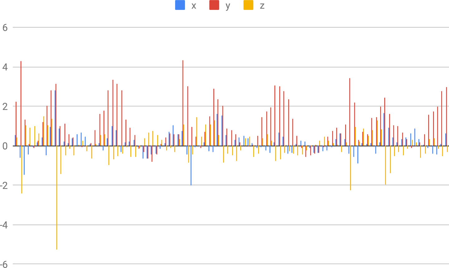
Figure 11-1. Graph showing data for a person who is jogging (MotionSense dataset)
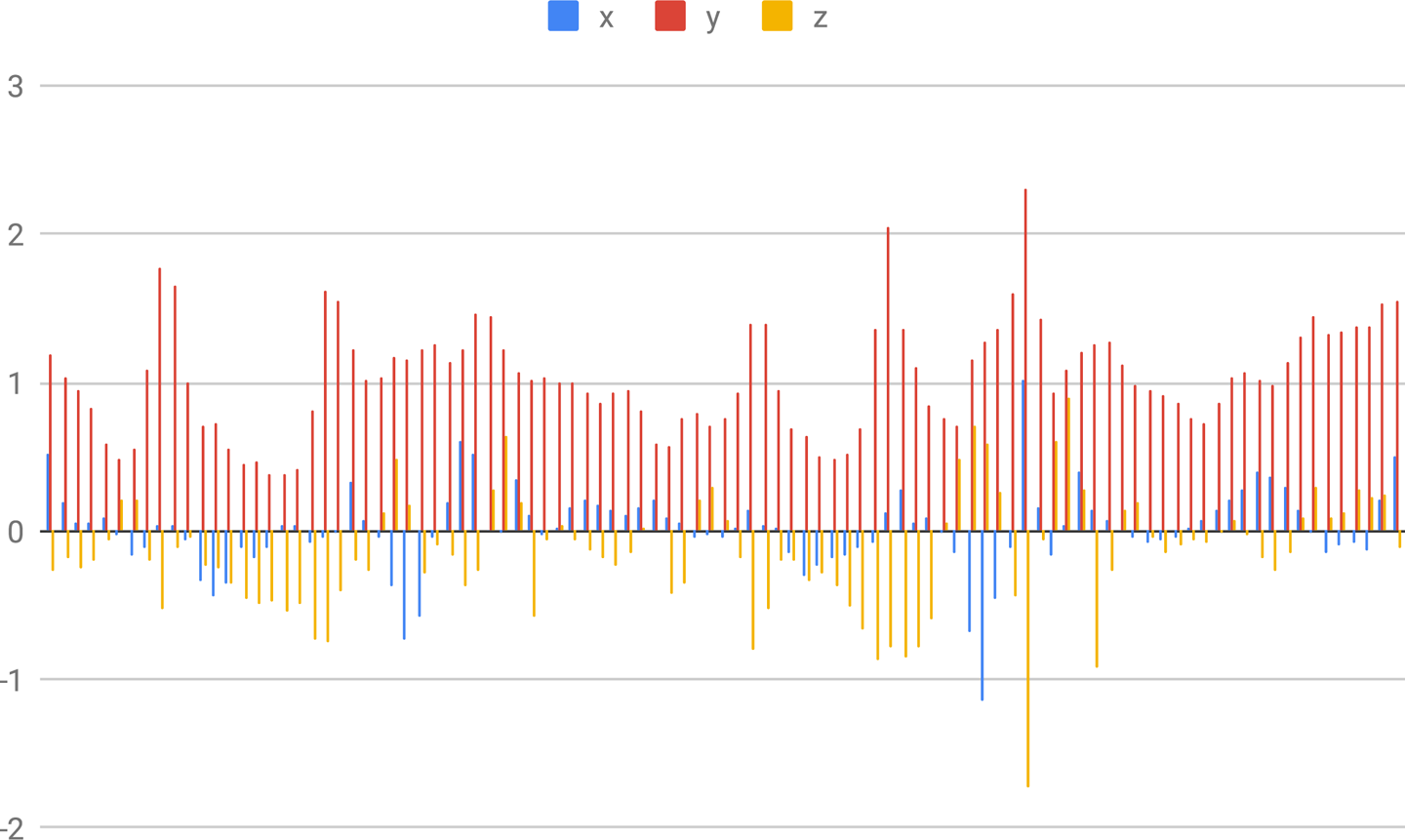
Figure 11-2. Graph showing data for a person who is walking down stairs (MotionSense dataset)
To create a heuristic, you need two things. The first is domain knowledge. A heuristic algorithm expresses human knowledge and understanding, so to write one, you need to already understand what the data means. To understand this, imagine a heuristic that determines whether a person has a fever based on their body temperature. Whoever created it must have had knowledge of the temperature changes that indicate a fever.
The second requirement for building a heuristic is programming and mathematical expertise. Although it’s fairly easy to determine whether someone’s temperature is too high, other problems can be far more complex. Discerning a system’s state based on complex patterns in multiple streams of data might require knowledge of some advanced techniques, like statistical analysis or signal processing. For example, imagine creating a heuristic to distinguish between walking and running based on accelerometer data. To build this, you might need to know how to mathematically filter the accelerometer data to get an estimate of step frequency.
Heuristics can be extremely useful, but the fact that they require domain knowledge and programming expertise means that they can be a challenge to build. First, domain knowledge is not always available. For example, a small company might not have the resources to conduct the basic research necessary to know what indicates one state versus another. Similarly, even given domain knowledge, not everyone has the expertise required to design and implement the heuristic algorithm in code.
Machine learning gives us an opportunity to shortcut these requirements. A model trained on labeled data can learn to recognize the signals that indicate one class or another, meaning there’s less need for deep domain knowledge. For example, a model can learn the human temperature fluctuations that indicate a fever without ever being told which specific temperatures are important—all it needs is temperature data labelled with “fever” or “nonfever.” In addition, the engineering skills required to work with machine learning are arguably easier to acquire than those that might be required to implement a sophisticated heuristic.
Instead of having to design a heuristic algorithm from scratch, a machine learning developer can find a suitable model architecture, collect and label a dataset, and iteratively create a model through training and evaluation. Domain knowledge is still extremely helpful, but it might no longer be a prerequisite to getting something working. And in some cases, the resulting model can actually be more accurate than the best handcoded algorithms.
In fact, a recent paper1 showed how a simple convolutional neural network is able to detect congestive heart failure in a patient from a single heartbeat with 100% accuracy. This is better performance than any previous diagnostic technique. The paper is a fascinating read, even if you don’t understand every detail.
By training a deep learning model to understand complex data and embedding it in a microcontroller program, we can create smart sensors that are able to understand the complexities of their environments and tell us, at a high level, what is going on. This has huge implications across dozens of fields. Here are just a few potential applications:
-
Environmental monitoring in remote places with poor connectivity
-
Automated industrial processes that adjust to problems in real time
-
Robots that react to complex external stimuli
-
Disease diagnosis without the need for medical professionals
-
Computer interfaces that understand physical movement
In this chapter, we build a project in the final category: a digital “magic wand,” which can be waved by its owner to cast a variety of spells. As its input, it takes complex, multidimensional sensor data that would be inscrutable to a human. Its output will be a simple classification that alerts us if one of several classes of movements has recently occurred. We’ll look at how deep learning can transform strange numerical data into meaningful information—to magical effect.
What We’re Building
Our “magic wand” can be used to cast several types of spells. To do so, the wielder need only wave the wand in one of three gestures, named “wing,” “ring,” and “slope,” as shown in Figure 11-3.
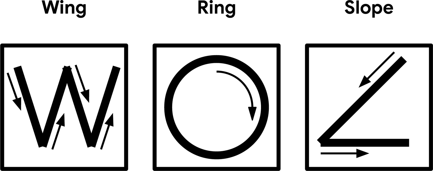
Figure 11-3. The three magic wand gestures
The wand will react to each spell by lighting an LED. In case the magic of electric light is not sufficiently exciting, it will also output information to its serial port, which can be used to control an attached computer.
To understand physical gestures, the magic wand application uses a device’s accelerometer to collect information about its motion through space. An accelerometer measures the degree of acceleration that it is currently experiencing. For example, imagine that we’ve attached an accelerometer to a car that has stopped at a red light and is about to drive away.
When the light turns green, the car starts moving forward, increasing in speed until it reaches the speed limit. During this period, the accelerometer will output a value that indicates the car’s rate of acceleration. After the car has reached a steady speed, it is no longer accelerating, so the accelerometer will output zero.
The SparkFun Edge and Arduino Nano 33 BLE Sense boards are both equipped with three-axis accelerometers contained within components that are soldered to each board. These measure acceleration in three directions, which means they can be used to track the motion of the device in 3D space. To construct our magic wand, we’ll attach the microcontroller board to the end of a stick so it can be waved in a sorcerous manner. We’ll then feed the accelerometer’s output into a deep learning model, which will perform classification to tell us whether a known gesture was made.
We provide instructions on deploying this application to the following microcontroller platforms:
Because the ST Microelectronics STM32F746G Discovery kit doesn’t include an accelerometer (and is too big to attach to the end of a magic wand), we won’t be featuring it here.
Note
TensorFlow Lite regularly adds support for new devices, so if the device you’d like to use isn’t listed here, it’s worth checking the example’s README.md. You can also check there for updated deployment instructions if you run into trouble.
In the next section, we’ll look at the structure of our application and learn more about how its model works.
Application Architecture
Our application will again follow the now-familiar pattern of obtaining input, running inference, processing the output, and using the resulting information to make things happen.
A three-axis accelerometer outputs three values representing the amount of acceleration on the device’s x, y, and z-axes. The accelerometer on the SparkFun Edge board can do this 25 times per second (a rate of 25 Hz). Our model takes these values directly as its input, meaning we won’t need to do any preprocessing.
After data has been captured and inference has been run, our application will determine whether a valid gesture was detected, print some output to the terminal, and light an LED.
Introducing Our Model
Our gesture-detecting model is a convolutional neural network, weighing in at around 20 KB, that accepts raw accelerometer values as its input. It takes in 128 sets of x, y, and z values at once, which at a rate of 25 Hz adds up to a little more than five seconds’ worth of data. Each value is a 32-bit floating-point number that indicates the amount of acceleration in that direction.
The model was trained on four gestures performed by numerous people. It outputs probability scores for four classes: one representing each gesture (“wing,” “ring,” and “slope”), and one representing no recognized gesture. The probability scores sum to 1, with a score above 0.8 being considered confident.
Because we’ll be running multiple inferences per second, we’ll need to make sure a single errant inference while a gesture is performed doesn’t skew our results. Our mechanism for doing this will be to consider a gesture as being detected only after it has been confirmed by a certain number of inferences. Given that each gesture takes a different amount of time to perform, the number of required inferences is different for each gesture, with the optimal numbers being determined through experimentation. Likewise, inference runs at varying rates on different devices, so these thresholds are also set per device.
In Chapter 12, we’ll explore how to train a model on our own gesture data and dig deeper into how the model works. Until then, let’s continue walking through our application.
All the Moving Parts
Figure 11-4 shows the structure of our magic wand application.
As you can see, it’s almost as simple as our person detection application. Our model accepts raw accelerometer data, meaning we don’t need to do any preprocessing.
The code’s six main parts follow a similar structure as in our person detection example. Let’s walk through them in turn:
- Main loop
-
Our application runs in a continuous loop. Since its model is small and simple and there’s no preprocessing required, we’ll be able to run multiple inferences per second.
- Accelerometer handler
-
This component captures data from the accelerometer and writes it to the model’s input tensor. It uses a buffer to hold data.
- TF Lite interpreter
-
The interpreter runs the TensorFlow Lite model, as in our earlier examples.
- Model
-
The model is included as a data array and run by the interpreter. It’s nice and small, weighing in at only 19.5 KB.
- Gesture predictor
-
This component takes the model’s output and decides whether a gesture has been detected, based on thresholds for both probability and the number of consecutive positive predictions.
- Output handler
-
The output handler lights LEDs and prints output to the serial port depending on which gesture was recognized.
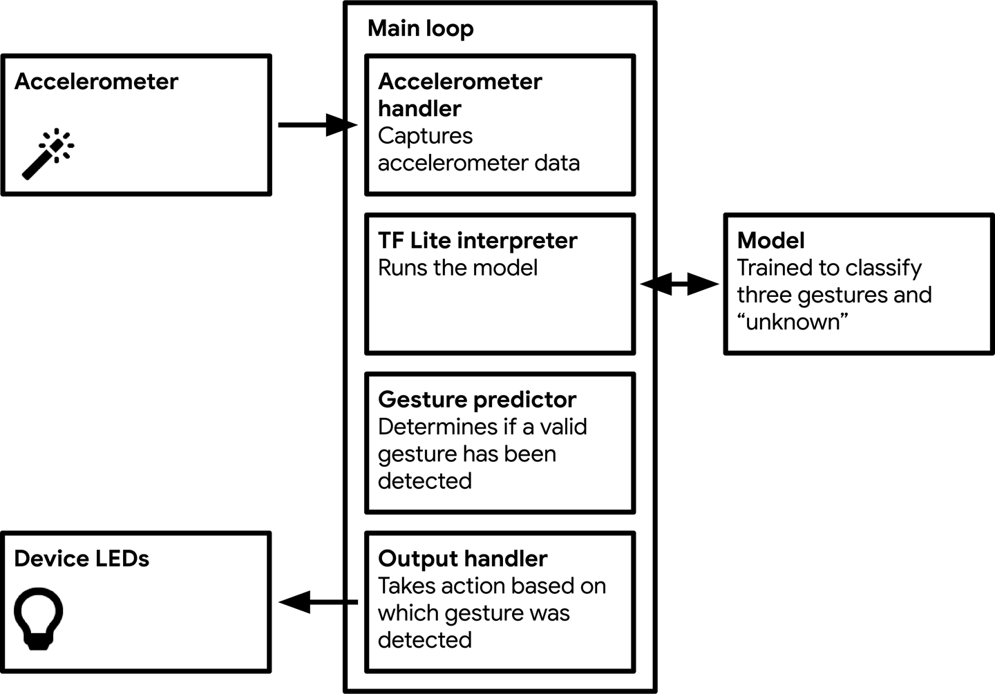
Figure 11-4. The components of our magic wand application
Walking Through the Tests
You can find the application’s tests in the GitHub repository:
- magic_wand_test.cc
-
Shows how to run inference on a sample of accelerometer data
- accelerometer_handler_test.cc
-
Shows how to use the accelerometer handler to obtain fresh data
- gesture_predictor_test.cc
-
Shows how to use the gesture predictor to interpret the results of inference
- output_handler_test.cc
-
Shows how to use the output handler to show results of inference
Let’s begin by walking through magic_wand_test.cc, which will show us the end-to-end process of inference with our model.
The Basic Flow
We step through the basic flow in magic_wand_test.cc.
First, we list the ops our model will need:
namespacetflite{namespaceops{namespacemicro{TfLiteRegistration*Register_DEPTHWISE_CONV_2D();TfLiteRegistration*Register_MAX_POOL_2D();TfLiteRegistration*Register_CONV_2D();TfLiteRegistration*Register_FULLY_CONNECTED();TfLiteRegistration*Register_SOFTMAX();}// namespace micro}// namespace ops}// namespace tflite
The test itself begins (as usual) by setting up everything required for inference and grabbing a pointer to the model’s input tensor:
// Set up loggingtflite::MicroErrorReportermicro_error_reporter;tflite::ErrorReporter*error_reporter=µ_error_reporter;// Map the model into a usable data structure. This doesn't involve any// copying or parsing, it's a very lightweight operation.consttflite::Model*model=::tflite::GetModel(g_magic_wand_model_data);if(model->version()!=TFLITE_SCHEMA_VERSION){error_reporter->Report("Model provided is schema version %d not equal ""to supported version %d.",model->version(),TFLITE_SCHEMA_VERSION);}statictflite::MicroMutableOpResolvermicro_mutable_op_resolver;micro_mutable_op_resolver.AddBuiltin(tflite::BuiltinOperator_DEPTHWISE_CONV_2D,tflite::ops::micro::Register_DEPTHWISE_CONV_2D());micro_mutable_op_resolver.AddBuiltin(tflite::BuiltinOperator_MAX_POOL_2D,tflite::ops::micro::Register_MAX_POOL_2D());micro_mutable_op_resolver.AddBuiltin(tflite::BuiltinOperator_CONV_2D,tflite::ops::micro::Register_CONV_2D());micro_mutable_op_resolver.AddBuiltin(tflite::BuiltinOperator_FULLY_CONNECTED,tflite::ops::micro::Register_FULLY_CONNECTED());micro_mutable_op_resolver.AddBuiltin(tflite::BuiltinOperator_SOFTMAX,tflite::ops::micro::Register_SOFTMAX());// Create an area of memory to use for input, output, and intermediate arrays.// Finding the minimum value for your model may require some trial and error.constinttensor_arena_size=60*1024;uint8_ttensor_arena[tensor_arena_size];// Build an interpreter to run the model withtflite::MicroInterpreterinterpreter(model,micro_mutable_op_resolver,tensor_arena,tensor_arena_size,error_reporter);// Allocate memory from the tensor_arena for the model's tensorsinterpreter.AllocateTensors();// Obtain a pointer to the model's input tensorTfLiteTensor*input=interpreter.input(0);
We then inspect the input tensor to ensure that it’s the expected shape:
// Make sure the input has the properties we expectTF_LITE_MICRO_EXPECT_NE(nullptr,input);TF_LITE_MICRO_EXPECT_EQ(4,input->dims->size);// The value of each element gives the length of the corresponding tensor.TF_LITE_MICRO_EXPECT_EQ(1,input->dims->data[0]);TF_LITE_MICRO_EXPECT_EQ(128,input->dims->data[1]);TF_LITE_MICRO_EXPECT_EQ(3,input->dims->data[2]);TF_LITE_MICRO_EXPECT_EQ(1,input->dims->data[3]);// The input is a 32 bit floating point valueTF_LITE_MICRO_EXPECT_EQ(kTfLiteFloat32,input->type);
Our input’s shape is (1, 128, 3, 1). The first dimension is just a wrapper around the second, which holds 128 three-axis accelerometer readings. Each reading has three values, one for each axis, and each value is wrapped within a single-element tensor. The inputs are all 32-bit floating-point values.
After we’ve confirmed the input shape, we write some data to the input tensor:
// Provide an input valueconstfloat*ring_features_data=g_circle_micro_f9643d42_nohash_4_data;error_reporter->Report("%d",input->bytes);for(inti=0;i<(input->bytes/sizeof(float));++i){input->data.f[i]=ring_features_data[i];}
The constant g_circle_micro_f9643d42_nohash_4_data is defined in circle_micro_features_data.cc; it contains an array of floating-point values representing one person’s attempt at performing a circle gesture. In the for loop, we step through this data and write each value into the input. We write only as many float values as the input tensor can hold.
Next, we run inference in the familiar manner:
// Run the model on this input and check that it succeedsTfLiteStatusinvoke_status=interpreter.Invoke();if(invoke_status!=kTfLiteOk){error_reporter->Report("Invoke failed");}TF_LITE_MICRO_EXPECT_EQ(kTfLiteOk,invoke_status);
Afterward, we investigate our output tensor to ensure that it’s the shape we expect:
// Obtain a pointer to the output tensor and make sure it has the// properties we expect.TfLiteTensor*output=interpreter.output(0);TF_LITE_MICRO_EXPECT_EQ(2,output->dims->size);TF_LITE_MICRO_EXPECT_EQ(1,output->dims->data[0]);TF_LITE_MICRO_EXPECT_EQ(4,output->dims->data[1]);TF_LITE_MICRO_EXPECT_EQ(kTfLiteFloat32,output->type);
It should have two dimensions: a single-element wrapper, and a set of four values that indicate our four probabilities (“wing,” “ring,” “slope,” and unknown). Each of these will be a 32-bit floating-point number.
We can then test our data to make sure the inference result is what we expect. We passed in data for a circle gesture, so we expect the “ring” score to be the highest:
// There are four possible classes in the output, each with a score.constintkWingIndex=0;constintkRingIndex=1;constintkSlopeIndex=2;constintkNegativeIndex=3;// Make sure that the expected "Ring" score is higher than the other// classes.floatwing_score=output->data.f[kWingIndex];floatring_score=output->data.f[kRingIndex];floatslope_score=output->data.f[kSlopeIndex];floatnegative_score=output->data.f[kNegativeIndex];TF_LITE_MICRO_EXPECT_GT(ring_score,wing_score);TF_LITE_MICRO_EXPECT_GT(ring_score,slope_score);TF_LITE_MICRO_EXPECT_GT(ring_score,negative_score);
We then repeat this entire process for the “slope” gesture:
// Now test with a different input, from a recording of "Slope".constfloat*slope_features_data=g_angle_micro_f2e59fea_nohash_1_data;for(inti=0;i<(input->bytes/sizeof(float));++i){input->data.f[i]=slope_features_data[i];}// Run the model on this "Slope" input.invoke_status=interpreter.Invoke();if(invoke_status!=kTfLiteOk){error_reporter->Report("Invoke failed");}TF_LITE_MICRO_EXPECT_EQ(kTfLiteOk,invoke_status);// Make sure that the expected "Slope" score is higher than the other classes.wing_score=output->data.f[kWingIndex];ring_score=output->data.f[kRingIndex];slope_score=output->data.f[kSlopeIndex];negative_score=output->data.f[kNegativeIndex];TF_LITE_MICRO_EXPECT_GT(slope_score,wing_score);TF_LITE_MICRO_EXPECT_GT(slope_score,ring_score);TF_LITE_MICRO_EXPECT_GT(slope_score,negative_score);
And that’s it! We’ve seen how we can run inference on raw accelerometer data. Like the previous example, the fact that we can avoid preprocessing keeps things nice and simple.
To run this test, use the following command:
make -f tensorflow/lite/micro/tools/make/Makefile test_magic_wand_test
The Accelerometer Handler
Our next test shows the interface for the accelerometer handler. This component’s task is to populate the input tensor with accelerometer data for each inference.
Because both of these things depend on how the device’s accelerometer works, a different accelerometer handler implementation is provided for each individual device. We’ll walk through these implementations later on, but for now, the tests located in accelerometer_handler_test.cc will show us how the handler should be called.
The first test is very simple:
TF_LITE_MICRO_TEST(TestSetup){statictflite::MicroErrorReportermicro_error_reporter;TfLiteStatussetup_status=SetupAccelerometer(µ_error_reporter);TF_LITE_MICRO_EXPECT_EQ(kTfLiteOk,setup_status);}
The SetupAccelerometer() function performs the one-time setup that needs to happen in order to obtain values from the accelerometer. The test shows how the function should be called (with a pointer to an ErrorReporter) and that it returns a TfLiteStatus indicating that setup was successful.
The next test shows how the accelerometer handler is used to fill the input tensor with data:
TF_LITE_MICRO_TEST(TestAccelerometer){floatinput[384]={0.0};tflite::MicroErrorReportermicro_error_reporter;// Test that the function returns false before insufficient data is availableboolinference_flag=ReadAccelerometer(µ_error_reporter,input,384,false);TF_LITE_MICRO_EXPECT_EQ(inference_flag,false);// Test that the function returns true once sufficient data is available to// fill the model's input buffer (128 sets of values)for(inti=1;i<=128;i++){inference_flag=ReadAccelerometer(µ_error_reporter,input,384,false);}TF_LITE_MICRO_EXPECT_EQ(inference_flag,true);}
First, we prepare a float array named input to simulate the model’s input tensor. Because there are 128 three-axis readings, it has a total size of 384 bytes (128 * 3). We initialize every value in the array to 0.0.
We then call ReadAccelerometer(). We provide an ErrorReporter instance, the array to which we want data to be written (input), and the total amount of data that we want to obtain (384 bytes). The final argument is a Boolean flag that instructs ReadAccelerometer() whether to clear the buffer before reading more data, which needs to be done after a gesture has been successfully recognized.
When called, the ReadAccelerometer() function attempts to write 384 bytes of data to the array passed to it. If the accelerometer has only just started collecting data, the full 384 bytes might not yet be available. In this case, the function will do nothing and return a value of false. We can use this to avoid running inference if no data is available.
The dummy implementation of the accelerometer handler, located in accelerometer_handler.cc, simulates another reading being available every time it is called. By calling it 127 additional times we ensure it will have accrued enough data to start returning true.
To run these tests, use the following command:
make-ftensorflow/lite/micro/tools/make/Makefiletest_gesture_accelerometer_handler_test
The Gesture Predictor
After inference has occurred, our output tensor will be filled with probabilities that indicate to us which gesture, if any, was made. However, because machine learning is not an exact science, there’s a chance that any single inference might result in a false positive.
To reduce the impact of false positives, we can stipulate that for a gesture to be recognized, it must have been detected in at least a certain number of consecutive inferences. Given that we run inference multiple times per second, we can quickly determine whether a result is valid. This is the job of the gesture predictor.
It defines a single function, PredictGesture(), which takes the model’s output tensor as its input. To determine whether a gesture has been detected, the function does two things:
-
Checks whether the gesture’s probability meets a minimum threshold
-
Checks whether the gesture has been consistently detected over a certain number of inferences
The minimum number of inferences required varies per gesture because some take longer to perform than others. It also varies per device, given that faster devices are able to run inference more frequently. The default values, tuned for the SparkFun Edge board, are located in constants.cc:
constintkConsecutiveInferenceThresholds[3]={15,12,10};
The values are defined in the same order as the gestures appear in the model’s output tensor. Other platforms, such as Arduino, have device-specific versions of this file that contain values tuned to their own performance.
Let’s walk through the code in gesture_predictor.cc to see how these are used.
First, we define some variables that are used to keep track of the last gesture seen and how many of the same gesture have been recorded in a row:
// How many times the most recent gesture has been matched in a rowintcontinuous_count=0;// The result of the last predictionintlast_predict=-1;
Next, we define the PredictGesture() function and determine whether any of the gesture categories had a probability of greater than 0.8 in the most recent inference:
// Return the result of the last prediction// 0: wing("W"), 1: ring("O"), 2: slope("angle"), 3: unknownintPredictGesture(float*output){// Find whichever output has a probability > 0.8 (they sum to 1)intthis_predict=-1;for(inti=0;i<3;i++){if(output[i]>0.8)this_predict=i;}
We use this_predict to store the index of the gesture that was predicted.
The variable continuous_count is used to track how many times the most recently spotted gesture has been predicted in a row. If none of the gesture categories meet the probability threshold of 0.8, we reset any ongoing detection process by setting continuous_count to 0, and last_predict to 3 (the index of the “unknown” category), indicating that the most recent result was no known gesture:
// No gesture was detected above the thresholdif(this_predict==-1){continuous_count=0;last_predict=3;return3;}
Next, if the most recent prediction aligns with the previous one, we increment continuous_count. Otherwise, we reset it to 0. We also store the most recent prediction in last_predict:
if(last_predict==this_predict){continuous_count+=1;}else{continuous_count=0;}last_predict=this_predict;
In the next section of PredictGesture(), we use should_continuous_count to check whether the current gesture has met its threshold yet. If it hasn’t, we return a 3, indicating an unknown gesture:
// If we haven't yet had enough consecutive matches for this gesture,// report a negative resultif(continuous_count<kConsecutiveInferenceThresholds[this_predict]){return3;}
If we get past this point, it means that we’ve confirmed a valid gesture. In this case, we reset all of our variables:
// Otherwise, we've seen a positive result, so clear all our variables// and report itcontinuous_count=0;last_predict=-1;returnthis_predict;}
The function ends by returning the current prediction. This will be passed by our main loop into the output handler, which displays the result to the user.
The gesture predictor’s tests are located in gesture_predictor_test.cc. The first test demonstrates a successful prediction:
TF_LITE_MICRO_TEST(SuccessfulPrediction){// Use the threshold from the 0th gestureintthreshold=kConsecutiveInferenceThresholds[0];floatprobabilities[4]={1.0,0.0,0.0,0.0};intprediction;// Loop just too few times to trigger a predictionfor(inti=0;i<=threshold-1;i++){prediction=PredictGesture(probabilities);TF_LITE_MICRO_EXPECT_EQ(prediction,3);}// Call once more, triggering a prediction// for category 0prediction=PredictGesture(probabilities);TF_LITE_MICRO_EXPECT_EQ(prediction,0);}
The PredictGesture() function is fed a set of probabilities that strongly indicate that the first category should be matched. However, until it has been called with these probabilities threshold number of times, it returns a 3, signifying an “unknown” result. After it has been called threshold number of times, it returns a positive prediction for category 0.
The next test shows what happens if a consecutive run of high probabilities for one category is interrupted by a high probability for a different category:
TF_LITE_MICRO_TEST(FailPartWayThere){// Use the threshold from the 0th gestureintthreshold=kConsecutiveInferenceThresholds[0];floatprobabilities[4]={1.0,0.0,0.0,0.0};intprediction;// Loop just too few times to trigger a predictionfor(inti=0;i<=threshold-1;i++){prediction=PredictGesture(probabilities);TF_LITE_MICRO_EXPECT_EQ(prediction,3);}// Call with a different prediction, triggering a failureprobabilities[0]=0.0;probabilities[2]=1.0;prediction=PredictGesture(probabilities);TF_LITE_MICRO_EXPECT_EQ(prediction,3);}
In this case, we feed in a set of consecutive high probabilities for category 0, but not a sufficient number to meet the threshold. We then change the probabilities so that category 2 is the highest, which results in a category 3 prediction, signifying an “unknown” gesture.
The final test shows how PredictGesture() ignores probabilities that are below its threshold. In a loop, we feed in exactly the correct number of predictions to meet category 0’s threshold. However, although category 0 has the highest probability, its value is 0.7, which is below PredictGesture()’s internal threshold of 0.8. This results in a category 3 “unknown” prediction:
TF_LITE_MICRO_TEST(InsufficientProbability){// Use the threshold from the 0th gestureintthreshold=kConsecutiveInferenceThresholds[0];// Below the probability threshold of 0.8floatprobabilities[4]={0.7,0.0,0.0,0.0};intprediction;// Loop the exact right number of timesfor(inti=0;i<=threshold;i++){prediction=PredictGesture(probabilities);TF_LITE_MICRO_EXPECT_EQ(prediction,3);}}
To run these tests, use the following command:
make -f tensorflow/lite/micro/tools/make/Makefile
The Output Handler
The output handler is very simple; it just takes the class index returned by PredictGesture() and displays the results to the user. Its test, in output_handler_test.cc, shows its interface:
TF_LITE_MICRO_TEST(TestCallability){tflite::MicroErrorReportermicro_error_reporter;tflite::ErrorReporter*error_reporter=µ_error_reporter;HandleOutput(error_reporter,0);HandleOutput(error_reporter,1);HandleOutput(error_reporter,2);HandleOutput(error_reporter,3);}
To run this test, use the following command:
make -f tensorflow/lite/micro/tools/make/Makefile
Detecting Gestures
All of these components come together in main_functions.cc, which contains the core logic of our program. First it sets up the usual variables, along with some extras:
namespacetflite{namespaceops{namespacemicro{TfLiteRegistration*Register_DEPTHWISE_CONV_2D();TfLiteRegistration*Register_MAX_POOL_2D();TfLiteRegistration*Register_CONV_2D();TfLiteRegistration*Register_FULLY_CONNECTED();TfLiteRegistration*Register_SOFTMAX();}// namespace micro}// namespace ops}// namespace tflite// Globals, used for compatibility with Arduino-style sketches.namespace{tflite::ErrorReporter*error_reporter=nullptr;consttflite::Model*model=nullptr;tflite::MicroInterpreter*interpreter=nullptr;TfLiteTensor*model_input=nullptr;intinput_length;// Create an area of memory to use for input, output, and intermediate arrays.// The size of this will depend on the model you're using, and may need to be// determined by experimentation.constexprintkTensorArenaSize=60*1024;uint8_ttensor_arena[kTensorArenaSize];// Whether we should clear the buffer next time we fetch databoolshould_clear_buffer=false;}// namespace
The input_length variable stores the length of the model’s input tensor, and the should_clear_buffer variable is a flag that indicates whether the accelerometer handler’s buffer should be cleared the next time it runs. Clearing the buffer is done after a successful detection result in order to provide a clean slate for subsequent inferences.
Next, the setup() function does all of the usual housekeeping so that we’re ready to run inference:
voidsetup(){// Set up logging. Google style is to avoid globals or statics because of// lifetime uncertainty, but since this has a trivial destructor it's okay.statictflite::MicroErrorReportermicro_error_reporter;//NOLINTerror_reporter=µ_error_reporter;// Map the model into a usable data structure. This doesn't involve any// copying or parsing, it's a very lightweight operation.model=tflite::GetModel(g_magic_wand_model_data);if(model->version()!=TFLITE_SCHEMA_VERSION){error_reporter->Report("Model provided is schema version %d not equal ""to supported version %d.",model->version(),TFLITE_SCHEMA_VERSION);return;}// Pull in only the operation implementations we need.// This relies on a complete list of all the ops needed by this graph.// An easier approach is to just use the AllOpsResolver, but this will// incur some penalty in code space for op implementations that are not// needed by this graph.statictflite::MicroMutableOpResolvermicro_mutable_op_resolver;// NOLINTmicro_mutable_op_resolver.AddBuiltin(tflite::BuiltinOperator_DEPTHWISE_CONV_2D,tflite::ops::micro::Register_DEPTHWISE_CONV_2D());micro_mutable_op_resolver.AddBuiltin(tflite::BuiltinOperator_MAX_POOL_2D,tflite::ops::micro::Register_MAX_POOL_2D());micro_mutable_op_resolver.AddBuiltin(tflite::BuiltinOperator_CONV_2D,tflite::ops::micro::Register_CONV_2D());micro_mutable_op_resolver.AddBuiltin(tflite::BuiltinOperator_FULLY_CONNECTED,tflite::ops::micro::Register_FULLY_CONNECTED());micro_mutable_op_resolver.AddBuiltin(tflite::BuiltinOperator_SOFTMAX,tflite::ops::micro::Register_SOFTMAX());// Build an interpreter to run the model withstatictflite::MicroInterpreterstatic_interpreter(model,micro_mutable_op_resolver,tensor_arena,kTensorArenaSize,error_reporter);interpreter=&static_interpreter;// Allocate memory from the tensor_arena for the model's tensorsinterpreter->AllocateTensors();// Obtain pointer to the model's input tensormodel_input=interpreter->input(0);if((model_input->dims->size!=4)||(model_input->dims->data[0]!=1)||(model_input->dims->data[1]!=128)||(model_input->dims->data[2]!=kChannelNumber)||(model_input->type!=kTfLiteFloat32)){error_reporter->Report("Bad input tensor parameters in model");return;}input_length=model_input->bytes/sizeof(float);TfLiteStatussetup_status=SetupAccelerometer(error_reporter);if(setup_status!=kTfLiteOk){error_reporter->Report("Set up failed");}}
The more interesting stuff happens in the loop() function, which is still very simple:
voidloop(){// Attempt to read new data from the accelerometerboolgot_data=ReadAccelerometer(error_reporter,model_input->data.f,input_length,should_clear_buffer);// Don't try to clear the buffer againshould_clear_buffer=false;// If there was no new data, wait until next timeif(!got_data)return;// Run inference, and report any errorTfLiteStatusinvoke_status=interpreter->Invoke();if(invoke_status!=kTfLiteOk){error_reporter->Report("Invoke failed on index: %d",begin_index);return;}// Analyze the results to obtain a predictionintgesture_index=PredictGesture(interpreter->output(0)->data.f);// Clear the buffer next time we read datashould_clear_buffer=gesture_index<3;// Produce an outputHandleOutput(error_reporter,gesture_index);}
First, we attempt to read some values from the accelerometer. After the attempt, we set should_clear_buffer to false to ensure that we stop trying to clear it for the time being.
If obtaining new data was unsuccessful, ReadAccelerometer() will return a false value, and we’ll return from the loop() function so that we can try again the next time it is called.
If the value returned by ReadAccelerometer() is true, we’ll run inference on our freshly populated input tensor. We pass the result into PredictGesture(), which gives us the index of which gesture was detected. If the index is less than 3, the gesture was valid, so we set the should_clear_buffer flag in order to clear the buffer next time ReadAccelerometer() is called. We then call HandleOutput() to report any results to the user.
Over in main.cc, the main() function kicks off our program, runs setup(), and calls the loop() function in a loop:
intmain(intargc,char*argv[]){setup();while(true){loop();}}
And that’s it! To build the program on your development computer, use the following command:
make -f tensorflow/lite/micro/tools/make/Makefile magic_wand
Then, to run the program, enter the following:
./tensorflow/lite/micro/tools/make/gen/osx_x86_64/bin/magic_wand
The program won’t produce any output, because there isn’t any accelerometer data available, but you can confirm that it builds and runs.
Next, we walk through the code for each platform that captures accelerometer data and produces an output. We also show how to deploy and run the application.
Deploying to Microcontrollers
In this section, we’ll deploy our code to two devices:
Let’s begin with the Arduino implementation.
Arduino
The Arduino Nano 33 BLE Sense has a three-axis accelerometer as well as Bluetooth support, and is small and lightweight—ideal for building a magic wand.
Let’s walk through the Arduino-specific implementations of some of the application’s key files.
Arduino constants
The constant kConsecutiveInferenceThresholds is redefined in the file arduino/constants.cc:
// The number of expected consecutive inferences for each gesture type.// Established with the Arduino Nano 33 BLE Sense.constintkConsecutiveInferenceThresholds[3]={8,5,4};
As mentioned earlier in the chapter, this constant stores the number of consecutive positive inferences required for each gesture to be considered detected. The number depends on how many inferences are run per second, which varies per device. Because the default numbers were calibrated for the SparkFun Edge, the Arduino implementation needs its own set of numbers. You can modify these thresholds to make inference more difficult or easier to trigger, but setting them too low will result in false positives.
Capturing accelerometer data on Arduino
The Arduino accelerometer handler is located in arduino/accelerometer_handler.cc. It has the task of capturing data from the accelerometer and writing it to the model’s input buffer.
The model we are using was trained using data from the SparkFun Edge board. The Edge’s accelerometer provides a set of readings at a rate of 25 Hz, or 25 times per second. To work correctly, it needs to be fed data that is captured at the same rate. As it turns out, the accelerometer on the Arduino Nano 33 BLE Sense board returns measurements at a rate of 119 Hz. This means that in addition to capturing data, we need to downsample it to suit our model.
Although it sounds very technical, downsampling is actually pretty easy. To reduce the sample rate of a signal, we can just throw away some of the data. We look at how this works in the following code.
First the implementation includes its own header file, along with some others:
#include "tensorflow/lite/micro/examples/magic_wand/accelerometer_handler.h"#include <Arduino.h>#include <Arduino_LSM9DS1.h>#include "tensorflow/lite/micro/examples/magic_wand/constants.h"
The file Arduino.h provides access to some basic features of the Arduino platform. The file Arduino_LSM9DS1.h is part of the Arduino_LSM9DS1 library, which we’ll be using to communicate with the board’s accelerometer.
Next, we set up some variables:
// A buffer holding the last 200 sets of 3-channel valuesfloatsave_data[600]={0.0};// Most recent position in the save_data bufferintbegin_index=0;// True if there is not yet enough data to run inferenceboolpending_initial_data=true;// How often we should save a measurement during downsamplingintsample_every_n;// The number of measurements since we last saved oneintsample_skip_counter=1;
These include a buffer we’ll be filling with our data, save_data, along with some variables for tracking our current position in the buffer and whether we have enough data to start running inference. The most interesting two variables, sample_every_n and sample_skip_counter, are used in the downsampling process. We’ll look at this more closely in a moment.
Next in the file, the SetupAccelerometer() function is called by the program’s main loop to get the board ready to capture data:
TfLiteStatusSetupAccelerometer(tflite::ErrorReporter*error_reporter){// Wait until we know the serial port is readywhile(!Serial){}// Switch on the IMUif(!IMU.begin()){error_reporter->Report("Failed to initialize IMU");returnkTfLiteError;}
Because we’ll be outputting a message to indicate that everything is ready to go, the first thing it does is make sure that the device’s serial port is ready. It then switches on the inertial measurement unit (IMU), which is the electronic component that contains the accelerometer. The IMU object comes from the Arduino_LSM9DS1 library.
The next step is to start thinking about downsampling. We first query the IMU library to determine the board’s sample rate. When we have that number, we divide it by our target sample rate, which is defined in kTargetHz as part of constants.h:
// Determine how many measurements to keep in order to// meet kTargetHzfloatsample_rate=IMU.accelerationSampleRate();sample_every_n=static_cast<int>(roundf(sample_rate/kTargetHz));
Our target rate is 25 Hz, and the board’s sample rate is 119 Hz; thus, the result of our division is 4.76. This lets us know how many of the 119 Hz samples we need to keep in order to attain the target sample rate of 25 Hz: 1 sample in every 4.76.
Because keeping a fractional number of samples is difficult, we use the roundf() function to round to the nearest number, 5. To downsample our signal, then, we need to keep one in every five measurements. This will result in an effective sample rate of 23.8 Hz, which is a close enough approximation that our model should work well. We store this value in the sample_every_n variable for use later.
Now that we’ve established the parameters of our downsampling, we give the user a message to inform them that the application is ready to go and then return from the SetupAccelerometer() function:
error_reporter->Report("Magic starts!");returnkTfLiteOk;}
Next up, we define ReadAccelerometer(). This function is tasked with capturing new data and writing it to the model’s output tensor. It begins with some code that is used to clear its internal buffer after a gesture has been successfully recognized, cleaning the slate for any subsequent gestures:
boolReadAccelerometer(tflite::ErrorReporter*error_reporter,float*input,intlength,boolreset_buffer){// Clear the buffer if required, e.g. after a successful predictionif(reset_buffer){memset(save_data,0,600*sizeof(float));begin_index=0;pending_initial_data=true;}
Next, we use the IMU library to check for available data in a loop. If there’s data available, we read it:
// Keep track of whether we stored any new databoolnew_data=false;// Loop through new samples and add to bufferwhile(IMU.accelerationAvailable()){floatx,y,z;// Read each sample, removing it from the device's FIFO bufferif(!IMU.readAcceleration(x,y,z)){error_reporter->Report("Failed to read data");break;}
The accelerometer on the Arduino Nano 33 BLE Sense board is equipped with something called a FIFO buffer. This is a special memory buffer, located on the accelerometer itself, which holds the most recent 32 measurements. Because it’s part of the accelerometer hardware, the FIFO buffer continues to accrue measurements even while our application code is running. If it weren’t for the FIFO buffer, we might lose a lot of data, meaning we wouldn’t have an accurate record of the gestures being made.
When we call IMU.accelerationAvailable(), we are querying the accelerometer to see whether new data is available in its FIFO buffer. Using our loop, we continue to read all the data from the buffer until there is none remaining.
Next up, we implement our super-simple downsampling algorithm:
// Throw away this sample unless it's the nthif(sample_skip_counter!=sample_every_n){sample_skip_counter+=1;continue;}
Our approach is to keep one in every n samples, where n is the number stored in sample_every_n. To do this, we maintain a counter, sample_skip_counter, which lets us know how many samples have been read since the last one we kept. For every measurement we read, we check whether it is the nth. If it isn’t, we continue the loop without writing the data anywhere, effectively throwing it away. This simple process leads to our data being downsampled.
If execution gets further than this point, we’re planning on keeping the data. To do this, we write it to consecutive positions in our save_data buffer:
// Write samples to our buffer, converting to milli-Gs// and flipping y and x order for compatibility with// model (sensor orientation is different on Arduino// Nano BLE Sense compared with SparkFun Edge)save_data[begin_index++]=y*1000;save_data[begin_index++]=x*1000;save_data[begin_index++]=z*1000;
Our model accepts accelerometer measurements in the order x, y, z. You’ll notice here that we’re writing the y value to the buffer before the x. This is because our model was trained on data captured on the SparkFun Edge board, whose accelerometer has its axes pointing in different physical directions to the one on the Arduino. This difference means that the SparkFun Edge’s x-axis is equivalent to the Arduino’s y-axis, and vice versa. By swapping these axes’ data in our code, we can make sure our model is being fed data that it can understand.
The final few lines of our loop do some housework, setting some state variables that are used in our loop:
// Since we took a sample, reset the skip countersample_skip_counter=1;// If we reached the end of the circle buffer, resetif(begin_index>=600){begin_index=0;}new_data=true;}
We reset our downsampling counter, make sure we don’t run off the end of our sample buffer, and set a flag to indicate that new data has been saved.
After grabbing this new data, we do some more checks. This time, we’re making sure that we have sufficient data to perform an inference. If not, or if new data was not captured this time around, we return from the function without doing anything:
// Skip this round if data is not ready yetif(!new_data){returnfalse;}// Check if we are ready for prediction or still pending more initial dataif(pending_initial_data&&begin_index>=200){pending_initial_data=false;}// Return if we don't have enough dataif(pending_initial_data){returnfalse;}
By returning false when there’s no new data, we make sure the calling function knows not to bother running inference.
If we got this far, we’ve obtained some new data. We copy the appropriate amount of data, including our new samples, to the input tensor:
// Copy the requested number of bytes to the provided input tensorfor(inti=0;i<length;++i){intring_array_index=begin_index+i-length;if(ring_array_index<0){ring_array_index+=600;}input[i]=save_data[ring_array_index];}returntrue;}
And that’s it! We’ve populated the input tensor and are ready to run inference. After inference has been run, the results are passed into the gesture predictor, which determines whether a valid gesture has been spotted. The result is passed into the output handler, which we walk through next.
Responding to gestures on Arduino
The output handler is defined in arduino/output_handler.cc. It’s nice and simple: all it does is log information to the serial port depending on which gesture was detected, and toggle the board’s LED each time inference is run.
The first time the function runs, the LED is configured for output:
voidHandleOutput(tflite::ErrorReporter*error_reporter,intkind){// The first time this method runs, set up our LEDstaticboolis_initialized=false;if(!is_initialized){pinMode(LED_BUILTIN,OUTPUT);is_initialized=true;}
Next, the LED is toggled on and off with each inference:
// Toggle the LED every time an inference is performedstaticintcount=0;++count;if(count&1){digitalWrite(LED_BUILTIN,HIGH);}else{digitalWrite(LED_BUILTIN,LOW);}
Finally, we print some beautiful ASCII art depending on which gesture was matched:
// Print some ASCII art for each gestureif(kind==0){error_reporter->Report("WING:* * ** * * ""** * * ** * * ** * ""* ** *");}elseif(kind==1){error_reporter->Report("RING:** ** *"" * ** ** *"" *");}elseif(kind==2){error_reporter->Report("SLOPE:****""**** * * * * * * *");}
It’s difficult to read now, but you’ll be rewarded with the output’s full glory when you deploy the application to your board.
Running the example
To deploy this example, here’s what we’ll need:
-
An Arduino Nano 33 BLE Sense board
-
A micro-USB cable
-
The Arduino IDE
Tip
There’s always a chance that the build process might have changed since this book was written, so check README.md for the latest instructions.
The projects in this book are available as example code in the TensorFlow Lite Arduino library. If you haven’t already installed the library, open the Arduino IDE and select Manage Libraries from the Tools menu. In the window that appears, search for and install the library named TensorFlowLite. You should be able to use the latest version, but if you run into issues, the version that was tested with this book is 1.14-ALPHA.
Note
You can also install the library from a .zip file, which you can either download from the TensorFlow Lite team or generate yourself using the TensorFlow Lite for Microcontrollers Makefile. If you’d prefer to do the latter, see Appendix A.
After you’ve installed the library, the magic_wand example will show up in the File menu under Examples→Arduino_TensorFlowLite, as shown in Figure 11-5.
Click “magic_wand” to load the example. It will appear as a new window, with a tab for each of the source files. The file in the first tab, magic_wand, is equivalent to the main_functions.cc we walked through earlier.
Note
“Running the Example” already explained the structure of the Arduino example, so we won’t cover it again here.
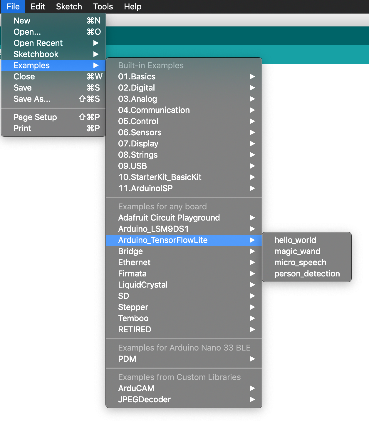
Figure 11-5. The Examples menu
In addition to the TensorFlow library, we also need to install and patch the Arduino_LSM9DS1 library. By default, the library doesn’t enable the FIFO buffer that is required by the example, so we have to make some modifications to its code.
In the Arduino IDE, select Tools→Manage Libraries and then search for Arduino_LSM9DS1. To ensure the following instructions work, you must install version 1.0.0 of the driver.
Note
It’s possible that the driver might have been fixed by the time you are reading this chapter. You can find the latest deployment instructions in README.md.
The driver will be installed to your Arduino/libraries directory, in the subdirectory Arduino_LSM9DS1.
Open the Arduino_LSM9DS1/src/LSM9DS1.cpp driver source file and then go to the function named LSM9DS1Class::begin(). Insert the following lines at the end of the function, immediately before the return 1 statement:
// Enable FIFO (see docs https://www.st.com/resource/en/datasheet/DM00103319.pdf)// writeRegister(LSM9DS1_ADDRESS, 0x23, 0x02);// Set continuous modewriteRegister(LSM9DS1_ADDRESS,0x2E,0xC0);
Next, locate the function named LSM9DS1Class::accelerationAvailable(). You will see the following lines:
if(readRegister(LSM9DS1_ADDRESS,LSM9DS1_STATUS_REG)&0x01){return1;}
Comment out those lines and then replace them with the following:
// Read FIFO_SRC. If any of the rightmost 8 bits have a value, there is data.if(readRegister(LSM9DS1_ADDRESS,0x2F)&63){return1;}
Save the file. Patching is now complete!
To run the example, plug in your Arduino device via USB. On the Tools menu, make sure that the correct device type is selected from the Board drop-down list, as shown in Figure 11-6.
If your device’s name doesn’t appear in the list, you’ll need to install its support package. To do this, click Boards Manager and then, in the window that appears, search for your device and install the latest version of the corresponding support package.
Next, make sure the device’s port is selected in the Port drop-down, also in the Tools menu, as demonstrated in Figure 11-7.
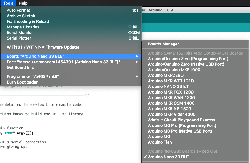
Figure 11-6. The Board drop-down list
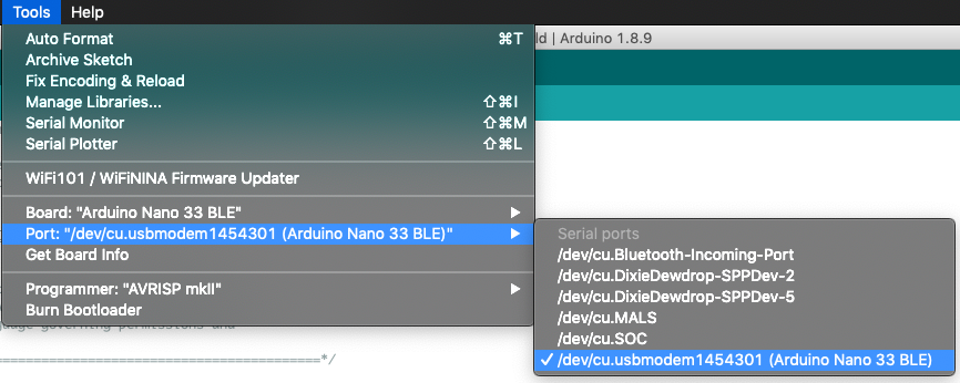
Figure 11-7. The Port drop-down list
Finally, click the upload button in the Arduino window (highlighted in white in Figure 11-8) to compile and upload the code to your Arduino device.
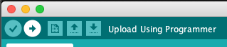
Figure 11-8. The upload button
After the upload has successfully completed, you should see the LED on your Arduino board begin to flash.
To try some gestures, select Serial Monitor in the Tools menu. You should initially see the following output:
Magic starts!
You can now try to make some gestures. Hold the board up with one hand, with the components facing up and the USB adapter facing toward the left, as shown in Figure 11-9.
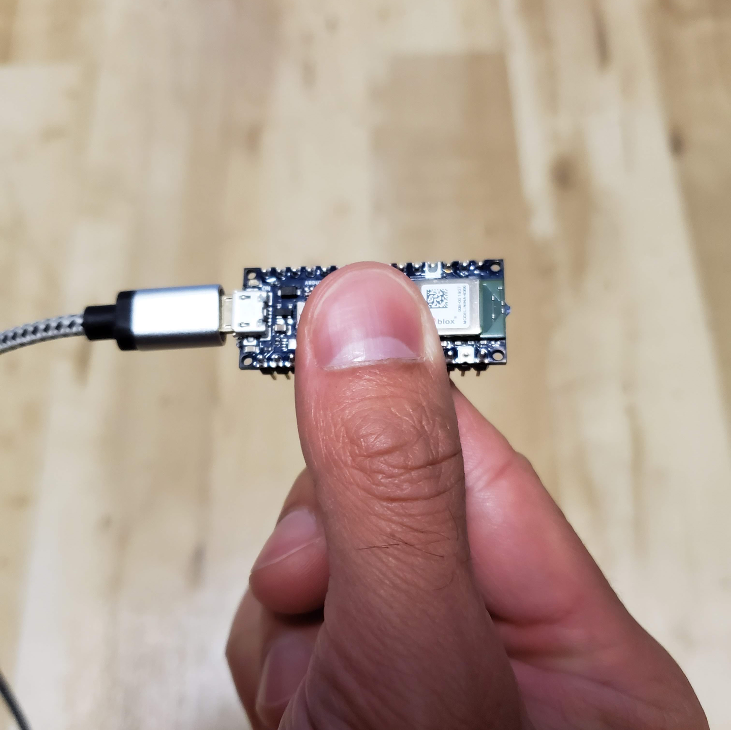
Figure 11-9. How to hold the board while performing gestures
Figure 11-10 presents a diagram showing how to perform each gesture. Because the model was trained on data collected when the board was attached to a wand, you might need a few tries to get them to work.
Figure 11-10. The three magic wand gestures
The easiest one to start with is “wing.” You should move your hand quickly enough that it takes around one second to perform the gesture. If you’re successful, you should see the following output, and the red LED should illuminate:
WING:
*         *         *
 *       * *       *
  *     *   *     *
   *   *     *   *
    * *       * *
     *         *
Congratulations, you’ve cast your first magic spell using the Arduino!
Note
At this point, you might choose to be creative and attach the board to the tip of a magic wand, at the point furthest from your hand. Any stick, ruler, or other household item with a length of around a foot (30 cm) should work well.
Make sure the device is attached firmly, and in the same orientation, with the components facing up and the USB adapter facing toward the left. And pick a rigid wand, not a flexible one; any wobbling will affect the accelerometer readings.
Next, try the “ring” gesture, by tracing a clockwise circle with your hand (or the tip of your wand). Again, aim to take around a second to perform the gesture. You should see the following appear, as if by magic:
RING:
          *
       *     *
     *         *
    *           *
     *         *
       *     *
          *
For the final gesture, trace the corner of a triangle in the air. It’s best described by its ASCII art demonstration, shown here:
SLOPE:
        *
       *
      *
     *
    *
   *
  *
 * * * * * * * *
Like any good magic spells, you might have to practice these a bit before you can perform them perfectly each time. You can see video demonstrations of the gestures in README.md.
Making your own changes
Now that you deployed the basic application, try playing around and making some changes to the code. Just edit the files in the Arduino IDE and save them, and then repeat the previous instructions to deploy your modified code to the device.
Here are a few things you could try:
-
Experiment with the threshold values in arduino/constants.cc to make the gestures easier or more difficult to perform (at the cost of more false positives or negatives).
-
Write a program on your computer that lets you perform tasks using physical gestures.
-
Extend the program to transmit detection results via Bluetooth. There are examples showing how to do this included with the ArduinoBLE library, which you can download via the Arduino IDE.
SparkFun Edge
The SparkFun Edge features a three-axis accelerometer, a battery mount, and Bluetooth support. This makes it perfect for a magic wand because it can operate wirelessly.
Capturing accelerometer data on SparkFun Edge
The code that captures accelerometer data is located in sparkfun_edge/accelerometer_handler.cc. A lot of it is device-specific, but we’ll skip over the implementation details and focus on the important stuff.
The first step involved with capturing accelerometer data is configuring the hardware. The SetupAccelerometer() function kicks this off by setting various low-level parameters required by the accelerometer:
TfLiteStatusSetupAccelerometer(tflite::ErrorReporter*error_reporter){// Set the clock frequency.am_hal_clkgen_control(AM_HAL_CLKGEN_CONTROL_SYSCLK_MAX,0);// Set the default cache configurationam_hal_cachectrl_config(&am_hal_cachectrl_defaults);am_hal_cachectrl_enable();// Configure the board for low power operation.am_bsp_low_power_init();// Collecting data at 25Hz.intaccInitRes=initAccelerometer();
You’ll notice a call to a function named initAccelerometer(). This is defined in the SparkFun Edge BSP’s accelerometer example, which is pulled down as a dependency when our project is built. It performs various tasks to switch on and configure the board’s accelerometer.
After the accelerometer is running, we enable its FIFO buffer. This is a special memory buffer, located on the accelerometer itself, which holds the last 32 datapoints. By enabling it, we’re able to continue collecting accelerometer measurements even while our application code is busy running inference. The remainder of the function sets up the buffer and logs errors if anything goes wrong:
// Enable the accelerometer's FIFO buffer.// Note: LIS2DH12 has a FIFO buffer which holds up to 32 data entries. It// accumulates data while the CPU is busy. Old data will be overwritten if// it's not fetched in time, so we need to make sure that model inference is// faster than 1/25Hz * 32 = 1.28sif(lis2dh12_fifo_set(&dev_ctx,1)){error_reporter->Report("Failed to enable FIFO buffer.");}if(lis2dh12_fifo_mode_set(&dev_ctx,LIS2DH12_BYPASS_MODE)){error_reporter->Report("Failed to clear FIFO buffer.");return0;}if(lis2dh12_fifo_mode_set(&dev_ctx,LIS2DH12_DYNAMIC_STREAM_MODE)){error_reporter->Report("Failed to set streaming mode.");return0;}error_reporter->Report("Magic starts!");returnkTfLiteOk;}
When we’re done with initialization, we can call the ReadAccelerometer() function to get the latest data. This will happen between every inference.
First, if the reset_buffer argument is true, ReadAccelerometer() performs a reset of its data buffer. This is done after a valid gesture has been detected in order to provide a clean slate for further gestures. As part of this process, we use am_util_delay_ms() to make our code wait for 10 ms. Without this delay, the code often hangs when reading new data (as of this writing, the cause was unclear, but the TensorFlow open source project welcomes pull requests if you determine a better fix):
boolReadAccelerometer(tflite::ErrorReporter*error_reporter,float*input,intlength,boolreset_buffer){// Clear the buffer if required, e.g. after a successful predictionif(reset_buffer){memset(save_data,0,600*sizeof(float));begin_index=0;pending_initial_data=true;// Wait 10ms after a reset to avoid hangam_util_delay_ms(10);}
After resetting the main buffer, ReadAccelerometer() checks whether there is any new data available in the accelerometer’s FIFO buffer. If there’s nothing available yet, we just return from the function:
// Check FIFO buffer for new sampleslis2dh12_fifo_src_reg_tstatus;if(lis2dh12_fifo_status_get(&dev_ctx,&status)){error_reporter->Report("Failed to get FIFO status.");returnfalse;}intsamples=status.fss;if(status.ovrn_fifo){samples++;}// Skip this round if data is not ready yetif(samples==0){returnfalse;}
Our application’s main loop will continue calling, meaning as soon as there’s data available, we can move past this point.
The next part of the function loops through the new data and stores it in another, larger buffer. First we set up a special struct of type axis3bit16_t, designed to hold accelerometer data. We then call lis2dh12_acceleration_raw_get() to fill it with the next available measurement. This function will return zero if it fails, at which point we display an error:
// Load data from FIFO bufferaxis3bit16_tdata_raw_acceleration;for(inti=0;i<samples;i++){// Zero out the struct that holds raw accelerometer datamemset(data_raw_acceleration.u8bit,0x00,3*sizeof(int16_t));// If the return value is non-zero, sensor data was successfully readif(lis2dh12_acceleration_raw_get(&dev_ctx,data_raw_acceleration.u8bit)){error_reporter->Report("Failed to get raw data.");
If the measurement was obtained successfully, we convert it into milli-Gs, the unit of measurement expected by the model, and then write it into save_data[], which is an array we’re using as a buffer to store values that we’ll use for inference. The values for each axis of the accelerometer are stored consecutively:
}else{// Convert each raw 16-bit value into floating point values representing// milli-Gs, a unit of acceleration, and store in the current position of// our buffersave_data[begin_index++]=lis2dh12_from_fs2_hr_to_mg(data_raw_acceleration.i16bit[0]);save_data[begin_index++]=lis2dh12_from_fs2_hr_to_mg(data_raw_acceleration.i16bit[1]);save_data[begin_index++]=lis2dh12_from_fs2_hr_to_mg(data_raw_acceleration.i16bit[2]);// Start from beginning, imitating loop array.if(begin_index>=600)begin_index=0;}}
Our save_data[] array can store 200 sets of three-axis values, so we set our begin_index counter back to 0 when it reaches 600.
We’ve now incorporated all of the new data into our save_data[] buffer. Next, we check whether we have enough data to make a prediction. When testing the model, it was discovered that around a third of our total buffer size is the bare minimum amount of data that results in a reliable prediction; therefore, if we have at least this much data, we set the pending_initial_data flag to false (it defaults to true):
// Check if we are ready for prediction or still pending more initial dataif(pending_initial_data&&begin_index>=200){pending_initial_data=false;}
Next, if there is still insufficient data to run an inference, we return false:
// Return if we don't have enough dataif(pending_initial_data){returnfalse;}
If we got this far, there’s sufficient data in the buffer to run an inference. The final part of the function copies the requested data from the buffer into the input argument, which is a pointer to the model’s input tensor:
// Copy the requested number of bytes to the provided input tensorfor(inti=0;i<length;++i){intring_array_index=begin_index+i-length;if(ring_array_index<0){ring_array_index+=600;}input[i]=save_data[ring_array_index];}returntrue;
The variable length is an argument passed into ReadAccelerometer() that determines how much data should be copied. Because our model takes 128 three-axis readings as its input, the code in main_functions.cc calls ReadAccelerometer() with a length of 384 (128 * 3).
At this point, our input tensor is filled with fresh accelerometer data. Inference will be run, the results will be interpreted by the gesture predictor, and the result will be passed to the output handler to display to the user.
Responding to gestures on SparkFun Edge
The output handler, located in sparkfun_edge/output_handler.cc, is very simple. The first time it runs, we configure the LEDs for output:
voidHandleOutput(tflite::ErrorReporter*error_reporter,intkind){// The first time this method runs, set up our LEDs correctlystaticboolis_initialized=false;if(!is_initialized){am_hal_gpio_pinconfig(AM_BSP_GPIO_LED_RED,g_AM_HAL_GPIO_OUTPUT_12);am_hal_gpio_pinconfig(AM_BSP_GPIO_LED_BLUE,g_AM_HAL_GPIO_OUTPUT_12);am_hal_gpio_pinconfig(AM_BSP_GPIO_LED_GREEN,g_AM_HAL_GPIO_OUTPUT_12);am_hal_gpio_pinconfig(AM_BSP_GPIO_LED_YELLOW,g_AM_HAL_GPIO_OUTPUT_12);is_initialized=true;}
Next, we toggle the yellow LED with each inference:
// Toggle the yellow LED every time an inference is performedstaticintcount=0;++count;if(count&1){am_hal_gpio_output_set(AM_BSP_GPIO_LED_YELLOW);}else{am_hal_gpio_output_clear(AM_BSP_GPIO_LED_YELLOW);}
After that, we check which gesture was detected. For each individual gesture, we light an LED, clear all the others, and output some beautiful ASCII art via the serial port. Here’s the code that handles the “wing” gesture:
// Set the LED color and print a symbol (red: wing, blue: ring, green: slope)if(kind==0){error_reporter->Report("WING:* * ** * * ""** * * ** * * ** * ""* ** *");am_hal_gpio_output_set(AM_BSP_GPIO_LED_RED);am_hal_gpio_output_clear(AM_BSP_GPIO_LED_BLUE);am_hal_gpio_output_clear(AM_BSP_GPIO_LED_GREEN);
On a serial port monitor, the output will look like this:
WING:
*         *         *
 *       * *       *
  *     *   *     *
   *   *     *   *
    * *       * *
     *         *
A different serial output and LED are used for each gesture.
Running the example
We’ve now seen how the SparkFun Edge code works. Next, let’s get it running on our hardware.
Tip
There’s always a chance that the build process might have changed since this book was written, so check README.md for the latest instructions.
To build and deploy our code, we’ll need the following:
-
A SparkFun Edge board with the Himax HM01B0 breakout attached
-
A USB programmer (we recommend the SparkFun Serial Basic Breakout, which is available in micro-B USB and USB-C variants)
-
A matching USB cable
-
Python 3 and some dependencies
Note
If you’re unsure whether you have the correct version of Python installed, “Running the Example” has instructions on how to check.
Open a terminal window, clone the TensorFlow repository, and then change into its directory:
git clone https://github.com/tensorflow/tensorflow.git
cd tensorflow
Next, we’re going to build the binary and run some commands that get it ready for downloading to the device. To avoid some typing, you can copy and paste these commands from README.md.
Build the binary
The following command downloads all the required dependencies and then compiles a binary for the SparkFun Edge:
make -f tensorflow/lite/micro/tools/make/MakefileTARGET=sparkfun_edge magic_wand_bin
The binary will be created as a .bin file, in the following location:
tensorflow/lite/micro/tools/make/gen/
 sparkfun_edge_cortex-m4/bin/magic_wand.bin
To check that the file exists, you can use the following command:
test-f tensorflow/lite/micro/tools/make/gen/sparkfun_edge_cortex-m4/bin/magic_wand.bin&&echo"Binary was successfully created"||echo"Binary is missing"
If you run that command, you should see Binary was successfully created printed to the console.
If you see Binary is missing, there was a problem with the build process. If so, it’s likely that there are some clues to what went wrong in the output of the make command.
Sign the binary
The binary must be signed with cryptographic keys to be deployed to the device. Let’s run some commands that will sign the binary so that it can be flashed to the SparkFun Edge. The scripts used here come from the Ambiq SDK, which is downloaded when the Makefile is run.
Enter the following command to set up some dummy cryptographic keys you can use for development:
cp tensorflow/lite/micro/tools/make/downloads/AmbiqSuite-Rel2.0.0/tools/apollo3_scripts/keys_info0.py tensorflow/lite/micro/tools/make/downloads/AmbiqSuite-Rel2.0.0/tools/apollo3_scripts/keys_info.py
Next, run the following command to create a signed binary. Substitute python3 with python if necessary:
python3 tensorflow/lite/micro/tools/make/downloads/AmbiqSuite-Rel2.0.0/tools/apollo3_scripts/create_cust_image_blob.py--bin tensorflow/lite/micro/tools/make/gen/sparkfun_edge_cortex-m4/bin/micro_vision.bin--load-address 0xC000--magic-num 0xCB-o main_nonsecure_ota--version 0x0
This creates the file main_nonsecure_ota.bin. Now, run this command to create a final version of the file that you can use to flash your device with the script you will use in the next step:
python3 tensorflow/lite/micro/tools/make/downloads/AmbiqSuite-Rel2.0.0/tools/apollo3_scripts/create_cust_wireupdate_blob.py--load-address 0x20000--bin main_nonsecure_ota.bin-i6-o main_nonsecure_wire--options 0x1
You should now have a file called main_nonsecure_wire.bin in the directory where you ran the commands. This is the file you’ll be flashing to the device.
Flash the binary
The SparkFun Edge stores the program it is currently running in its 1 megabyte of flash memory. If you want the board to run a new program, you need to send it to the board, which will store it in flash memory, overwriting any program that was previously saved. This process is called flashing.
Attach the programmer to the board
To download new programs to the board, you’ll use the SparkFun USB-C Serial Basic serial programmer. This device allows your computer to communicate with the microcontroller via USB.
To attach this device to your board, perform the following steps:
-
On the side of the SparkFun Edge, locate the six-pin header.
-
Plug the SparkFun USB-C Serial Basic into these pins, ensuring that the pins labeled BLK and GRN on each device are lined up correctly.
You can see the correct arrangement in Figure 11-11.
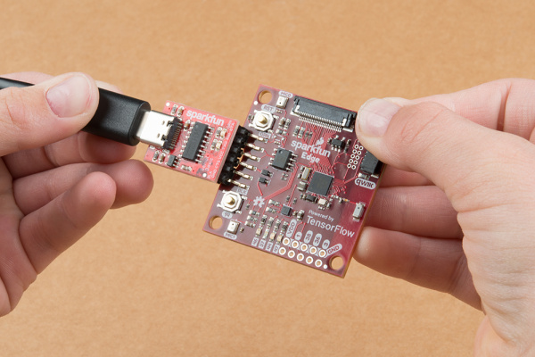
Figure 11-11. Connecting the SparkFun Edge and USB-C Serial Basic (image courtesy of SparkFun)
Attach the programmer to your computer
Next, connect the board to your computer via USB. To program the board, you need to determine the name that your computer gives the device. The best way of doing this is to list all the computer’s devices before and after attaching it and then look to see which device is new.
Warning
Some people have reported issues with their operating system’s default drivers for the programmer, so we strongly recommend installing the driver before you continue.
Before attaching the device via USB, run the following command:
# macOS:ls /dev/cu*# Linux:ls /dev/tty*
This should output a list of attached devices that looks something like the following:
/dev/cu.Bluetooth-Incoming-Port
/dev/cu.MALS
/dev/cu.SOC
Now, connect the programmer to your computer’s USB port and run the command again:
# macOS:ls /dev/cu*# Linux:ls /dev/tty*
You should see an extra item in the output, as in the example that follows. Your new item might have a different name. This new item is the name of the device:
/dev/cu.Bluetooth-Incoming-Port
/dev/cu.MALS
/dev/cu.SOC
/dev/cu.wchusbserial-1450
This name will be used to refer to the device. However, it can change depending on which USB port the programmer is attached to, so if you disconnect the board from your computer and then reattach it you might need to look up its name again.
Tip
Some users have reported two devices appearing in the list. If you see two devices, the correct one to use begins with the letters “wch”; for example, “/dev/wchusbserial-14410.”
After you’ve identified the device name, put it in a shell variable for later use:
export DEVICENAME=<your device name here>
This is a variable that you can use when running commands that require the device name, later in the process.
Run the script to flash your board
To flash the board, you need to put it into a special “bootloader” state that prepares it to receive the new binary. You can then run a script to send the binary to the board.
First create an environment variable to specify the baud rate, which is the speed at which data will be sent to the device:
exportBAUD_RATE=921600
Now paste the command that follows into your terminal—but do not press Enter yet!. The ${DEVICENAME} and ${BAUD_RATE} in the command will be replaced with the values you set in the previous sections. Remember to substitute python3 with python if necessary:
python3 tensorflow/lite/micro/tools/make/downloads/AmbiqSuite-Rel2.0.0/tools/apollo3_scripts/uart_wired_update.py -b${BAUD_RATE}${DEVICENAME}-r1-f main_nonsecure_wire.bin -i 6
Next you’ll reset the board into its bootloader state and flash the board.
On the board, locate the buttons marked RST and 14, as shown in Figure 11-12.
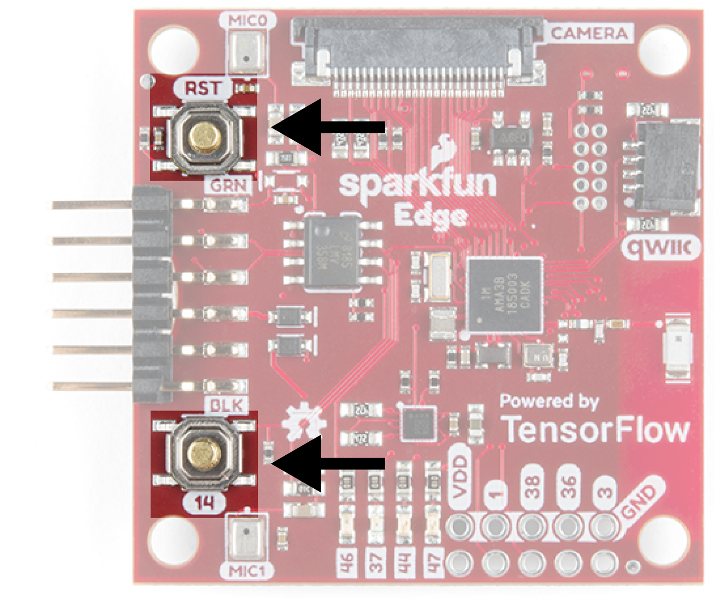
Figure 11-12. The SparkFun Edge’s buttons
Perform the following steps:
-
Ensure that your board is connected to the programmer, and the entire thing is connected to your computer via USB.
-
On the board, press and hold the button marked
14. Continue holding it. -
While still holding the button marked
14, press the button markedRSTto reset the board. -
Press Enter on your computer to run the script. Continue holding button
14.
You should now see something like the following appearing on your screen:
Connecting with Corvette over serial port /dev/cu.usbserial-1440...
Sending Hello.
Received response for Hello
Received Status
length =  0x58
version =  0x3
Max Storage =  0x4ffa0
Status =  0x2
State =  0x7
AMInfo =
0x1
0xff2da3ff
0x55fff
0x1
0x49f40003
0xffffffff
[...lots more 0xffffffff...]
Sending OTA Descriptor =  0xfe000
Sending Update Command.
number of updates needed =  1
Sending block of size  0x158b0  from  0x0  to  0x158b0
Sending Data Packet of length  8180
Sending Data Packet of length  8180
[...lots more Sending Data Packet of length  8180...]
Keep holding button 14 until you see Sending Data Packet of length 8180. You can release the button after seeing this (but it’s okay if you keep holding it).
The program will continue to print lines on the terminal. Eventually, you’ll see something like the following:
[...lots more Sending Data Packet of length  8180...]
Sending Data Packet of length  8180
Sending Data Packet of length  6440
Sending Reset Command.
Done.
This indicates a successful flashing.
Testing the Program
Start by pressing the RST button to make sure the program is running. When the program is running, the yellow LED will toggle on and off, once for each inference.
Next, use the following command to start printing the serial output of the device:
screen${DEVICENAME}115200
You should initially see the following output:
Magic starts!
You can now try to make some gestures. Hold the board up with one hand, with the components facing up and the USB adapter facing toward the left, as shown in Figure 11-13.
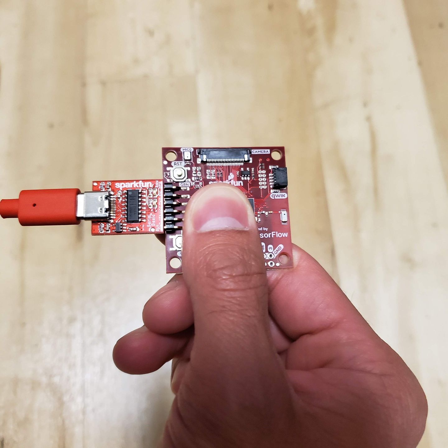
Figure 11-13. How to hold the board while performing gestures
Figure 11-14 presents a diagram showing how to perform each gesture. Because the model was trained on data collected when the board was attached to a wand, you might need a few tries to get them to work.
Figure 11-14. The three magic wand gestures
The easiest one to start with is “wing.” You should move your hand quickly enough that it takes around one second to perform the gesture. If you’re successful, the red LED should illuminate, and you should see the following output:
WING:
*         *         *
 *       * *       *
  *     *   *     *
   *   *     *   *
    * *       * *
     *         *
Congratulations, you’ve cast your first magic spell using the SparkFun Edge!
Note
At this point, you might choose to be creative and attach the board to the tip of a magic wand, at the point furthest from your hand. Any stick, ruler, or other household item with a length of around a foot (30 cm) should work well.
Make sure the device is attached firmly, and in the same orientation, with the components facing up and the USB adapter facing toward the left. And pick a rigid wand, not a flexible one because any wobbling will affect the accelerometer readings.
Next try the “ring” gesture, by tracing a clockwise circle with your hand (or the tip of your wand). Again, aim to take around a second to perform the gesture. You should see the following appear, as if by magic:
RING:
          *
       *     *
     *         *
    *           *
     *         *
       *     *
          *
For the final gesture, trace the corner of a triangle in the air. It’s best described by its ASCII art demonstration, shown here:
SLOPE:
        *
       *
      *
     *
    *
   *
  *
 * * * * * * * *
Like any good magic spells, you might have to practice these a bit before you can perform them perfectly each time. You can see video demonstrations of the gestures in README.md.
Making your own changes
Now that you’ve deployed the basic application, try playing around and making some changes. You can find the application’s code in the tensorflow/lite/micro/examples/magic_wand folder. Just edit and save, and then repeat the previous instructions to deploy your modified code to the device.
Here are a few things you could try:
-
Experiment with the threshold values in constants.cc to make the gestures easier or more difficult to perform (at the cost of more false positives or negatives).
-
Write a program on your computer that lets you perform tasks using physical gestures.
-
Extend the program to transmit detection results via Bluetooth. There’s an example of how to do this in the Ambiq SDK, in AmbiqSuite-Rel2.0.0/boards/apollo3_evb/examples/uart_ble_bridge. When the magic wand application is built, the SDK is downloaded to tensorflow/tensorflow/lite/micro/tools/make/downloads/AmbiqSuite-Rel2.0.0.
Wrapping Up
In this chapter, you saw a fun example of how obscure sensor data can be interpreted by an embedded machine learning application into a much more useful form. By seeing the patterns in noise, embedded machine learning models allow devices to understand the world around them and alert us to events, even when the raw data might be difficult for a human to digest.
In Chapter 12, we explore how our magic wand model works and learn how to collect data and train our own magic spells.
1 Mihaela Porumb et al., “A convolutional neural network approach to detect congestive heart failure.” Biomedical Signal Processing and Control (Jan 2020). https://oreil.ly/4HBFt