Deadlock, Livelock, and Starvation
The nodes of an interconnection network send and receive messages or packets through the network interface. Both messages and packets carry information about the destination node. Thus, the techniques described in this chapter can be applied to both of them indistinctly. Without loss of generality, in what follows we will only refer to packets.
In direct networks, packets usually travel across several intermediate nodes before reaching the destination. In switch-based networks, packets usually traverse several switches before reaching the destination. However, it may happen that some packets are not able to reach their destinations, even if there exist fault-free paths connecting the source and destination nodes for every packet. Assuming that the routing algorithm is able to use those paths, there are several situations that may prevent packet delivery. This chapter studies those situations and proposes techniques to guarantee packet delivery.
As seen in Chapter 2, some buffers are required to store fragments of each packet, or even the whole packet, at each intermediate node or switch. However, buffer storage is not free. Thus, buffer capacity is finite. As each packet whose header has not already arrived at its destination requests some buffers while keeping the buffers currently storing the packet, a deadlock may arise. A deadlock occurs when some packets cannot advance toward their destination because the buffers requested by them are full. All the packets involved in a deadlocked configuration are blocked forever. Note that a packet may be permanently blocked in the network because the destination node does not consume it. This kind of deadlock is produced by the application, and it is beyond the scope of this book. In this chapter, we will assume that packets are always consumed by the destination node in finite time. Therefore, in a deadlocked configuration, a set of packets is blocked forever. Every packet is requesting resources held by other packet(s) while holding resources requested by other packet(s).
A different situation arises when some packets are not able to reach their destination, even if they never block permanently. A packet may be traveling around its destination node, never reaching it because the channels required to do so are occupied by other packets. This situation is known as livelock. It can only occur when packets are allowed to follow nonminimal paths.
Finally, a packet may be permanently stopped if traffic is intense and the resources requested by it are always granted to other packets also requesting them. This situation is known as starvation, and it usually occurs when an incorrect resource assignment scheme is used to arbitrate in case of conflict.
Deadlocks, livelocks, and starvation arise because the number of resources is finite. Additionally, some of these situations may produce the others. For instance, a deadlock permanently blocks some packets. As those packets are occupying some buffers, other packets may require them to reach their destination, being continuously misrouted around their destination node and producing livelock.
It is extremely important to remove deadlocks, livelocks, and starvation when implementing an interconnection network. Otherwise, some packets may never reach their destination. As these situations arise because the storage resources are finite, the probability of reaching them increases with network traffic and decreases with the amount of buffer storage. For instance, a network using wormhole switching is much more deadlock-prone than the same network using SAF switching if the routing algorithm is not deadlock-free.
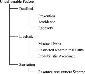
A classification of the situations that may prevent packet delivery and the techniques to solve these situations is shown in Figure 3.1. Starvation is relatively easy to solve. Simply, a correct resource assignment scheme should be used. A simple demand-slotted round-robin scheme is enough to produce a fair use of resources. When some packets must have a higher priority, some bandwidth must be reserved for low-priority packets in order to prevent starvation. This can be done by limiting the number of high-priority packets or by reserving some virtual channels or buffers for low-priority packets.
Livelock is also relatively easy to avoid. The simplest way consists of using only minimal paths. This restriction usually increases performance in networks using wormhole switching because packets do not occupy more channels than the ones strictly necessary to reach their destination. The main motivation for the use of nonminimal paths is fault tolerance. Even when nonminimal paths are used, livelock can be prevented by limiting the number of misrouting operations. Another motivation for using nonminimal paths is deadlock avoidance when deflection routing is used. In this case, routing is probabilistically livelock-free. This issue will be analyzed in Section 3.7.
Deadlock is by far the most difficult problem to solve. This chapter is almost completely dedicated to this subject. There are three strategies for deadlock handling: deadlock prevention, deadlock avoidance, and deadlock recovery1 [321]. In deadlock prevention, resources (channels or buffers) are granted to a packet in such a way that a request never leads to a deadlock. It can be achieved by reserving all the required resources before starting packet transmission. This is the case for all the variants of circuit switching when backtracking is allowed. In deadlock avoidance, resources are requested as a packet advances through the network. However, a resource is granted to a packet only if the resulting global state is safe. This strategy should avoid sending additional packets to update the global state because these packets consume network bandwidth and they may contribute to produce deadlock. Achieving this in a distributed manner is not an easy task. A common technique consists of establishing an ordering between resources and granting resources to each packet in decreasing order. In deadlock recovery strategies, resources are granted to a packet without any check. Therefore, deadlock is possible and some detection mechanism must be provided. If a deadlock is detected, some resources are deallocated and granted to other packets. In order to deallocate resources, packets holding those resources are usually aborted.
Deadlock prevention strategies are very conservative. However, reserving all the required resources before starting packet transmission may lead to a low resource utilization. Deadlock avoidance strategies are less conservative, requesting resources when they are really needed to forward a packet. Finally, deadlock recovery strategies are optimistic. They can only be used if deadlocks are rare and the result of a deadlock can be tolerated. Deadlock avoidance and recovery techniques considerably evolved during the last few years, making obsolete most of the previous proposals. In this chapter we present a unified approach to deadlock avoidance for the most important flow control techniques proposed up to now. With a simple trick, this technique is also valid for deadlock recovery. Also, we will survey the most interesting deadlock-handling strategies proposed up to now. The techniques studied in this chapter are restricted to unicast routing in fault-free networks. Deadlock handling in multicast routing and fault-tolerant routing will be studied in Chapters 5 and 6, respectively.
This chapter is organized as follows. Section 3.1 proposes a necessary and sufficient condition for deadlock-free routing in direct networks, giving application examples for SAF, VCT, and wormhole switching. This theory is extended in Section 3.2 by grouping channels into classes, extending the domain of the routing function, and considering central queues instead of edge buffers. Alternative approaches for deadlock avoidance are considered in Section 3.3. Switch-based networks are considered in Section 3.4. Deadlock prevention and recovery are covered in Sections 3.5 and 3.6, respectively. Finally, livelock avoidance is studied in Section 3.7. The chapter ends with a discussion of some engineering issues and commented references.
3.1 A Theory of Deadlock Avoidance
This section proposes a necessary and sufficient condition for deadlock-free routing in direct networks using SAF, VCT, or wormhole switching. For the sake of clarity, this theory is presented in an informal way. A formal version of this theory, restricted to wormhole switching, can be found in Appendix A. Section 3.4 shows the application of this condition to switch-based networks. The results for wormhole switching can also be applied to mad postman switching, assuming that dead flits are removed from the network as soon as they are blocked. Necessary and sufficient conditions for wormhole switching become sufficient conditions when applied to scouting switching.
3.1.1 Network and Router Models
Direct networks consist of a set of nodes interconnected by point-to-point links or channels. No restriction is imposed on the topology of the interconnection network. Each node has a router. The architecture of a generic router was described in Section 2.1. In this section, we highlight the aspects that affect deadlock avoidance.
We assume that the switch is a crossbar, therefore allowing multiple packets to traverse a node simultaneously without interference. The routing and arbitration unit configures the switch, determining the output channel for each packet as a function of the destination node, the current node, and the output channel status. The routing and arbitration unit can only process one packet header at a time. If there is contention for this unit, access is round-robin. When a packet gets the routing and arbitration unit but cannot be routed because all the valid output channels are busy, it waits in the corresponding input buffer until its next turn. By doing so, the packet gets the first valid channel that becomes available when it is routed again. This strategy achieves a higher routing flexibility than strategies in which blocked packets wait on a single predetermined channel.
Physical channels are bidirectional full duplex. Physical channels may be split into virtual channels. Virtual channels are assigned the physical channel cyclically, only if they are ready to transfer a flit (demand-slotted round-robin). In wormhole switching, each virtual channel may have buffers at both ends, although configurations without output buffers are also supported. In both cases, we will refer to the total buffer storage associated with a virtual channel as the channel queue.
For SAF and VCT switching with edge buffers (buffers associated with input channels), we assume the same model except that the buffers associated with input channels must be large enough to store one or more packets. These buffers are required to remove packets from the network whenever no output channel is available. A channel will only accept a new packet if there is enough buffer space to store the whole packet. The message flow control protocol is responsible for ensuring the availability of buffer space.
The above-described model uses edge buffers. However, most routing functions proposed up to now for SAF switching use central queues. The theory presented in the next sections is also valid for SAF and VCT switching with central queues after introducing some changes in notation. Those changes will be summarized in Section 3.2.3. In this case, a few central buffers deep enough to store one or more packets are used. As above, a channel will only accept a new packet if there is enough buffer space to store the whole packet. Buffer space must be reserved before starting packet transmission, thus preventing other channels from reserving the same buffer space. The message flow control protocol is responsible for ensuring the availability of buffer space and arbitrating between concurrent requests for space in the central queues.
As we will see in Section 3.2.3, it is also possible to consider models that mix both kinds of resources, edge buffers and central queues. It will be useful in Section 3.6. In this case, each node has edge buffers and central queues. The routing function determines the resource to be used in each case. This mixed model may consider either flit buffers or packet buffers, depending on the switching technique. For the sake of clarity, we will restrict definitions and examples to use only edge buffers. Results can be easily generalized by introducing the changes in notation indicated in Section 3.2.3.
3.1.2 Basic Definitions
The interconnection network I is modeled by using a strongly connected directed graph with multiple arcs, I = G(N, C). The vertices of the graph N represent the set of processing nodes. The arcs of the graph C represent the set of communication channels. More than a single channel is allowed to connect a given pair of nodes. Bidirectional channels are considered as two unidirectional channels. We will refer to a channel and its associated edge buffer indistinctly. The source and destination nodes of a channel ci are denoted si and di, respectively.
A routing algorithm is modeled by means of two functions: routing and selection. The routing function supplies a set of output channels based on the current and destination nodes. A selection from this set is made by the selection function based on the status of output channels at the current node. This selection is performed in such a way that a free channel (if any) is supplied. If all the output channels are busy, the packet will be routed again until it is able to reserve a channel, thus getting the first channel that becomes available. As we will see, the routing function determines whether the routing algorithm is deadlock-free or not. The selection function only affects performance.
Note that, in our model, the domain of the routing function is N × N because it only takes into account the current and destination nodes. Thus, we do not consider the path followed by the packet while computing the next channel to be used. We do not even consider the input channel on which the packet arrived at the current node. The reason for this choice is that it enables the design of practical routing protocols for which specific properties can be proven. These results may not be valid for other routing functions. Furthermore, this approach enables the development of methodologies for the design of fully adaptive routing protocols (covered in Chapter 4). These methodologies are invalid for other routing functions. Thus, this choice is motivated by engineering practice that is developed without sacrifice in rigor. Other definitions of the routing function will be considered in Section 3.2.
In order to make the theoretical results as general as possible, we assume no restriction about packet generation rate, packet destinations, and packet length. Also, we assume no restriction on the paths supplied by the routing algorithm. Both minimal and nonminimal paths are allowed. However, for performance reasons, a routing algorithm should supply at least one channel belonging to a minimal path at each intermediate node. Additionally, we are going to focus on deadlocks produced by the interconnection network. Thus, we assume that packets will be consumed at their destination nodes in finite time.
Several switching techniques can be used. Each of them will be considered as a particular case of the general theory. However, a few specific assumptions are required for some switching techniques. For SAF and VCT switching, we assume that edge buffers are used. Central queues will be considered in Section 3.2.3. For wormhole switching, we assume that a queue cannot contain flits belonging to different packets. After accepting a tail flit, a queue must be emptied before accepting another header flit. When a virtual channel has queues at both ends, both queues must be emptied before accepting another header flit. Thus, when a packet is blocked, its header flit will always occupy the head of a queue. Also, for every path P that can be established by a routing function R, all subpaths of P are also paths of R. The routing functions satisfying the latter property will be referred to as coherent. For mad postman switching, we assume the same restrictions as for wormhole switching. Additionally, dead flits are removed from the network as soon as they are blocked.
A configuration is an assignment of a set of packets or flits to each queue. Before analyzing how to avoid deadlocks, we are going to present a deadlocked configuration by using an example.
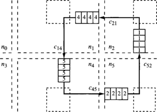
Consider a 2-D mesh with bidirectional channels. The routing function R forwards packets following any minimal path. This routing function is not deadlock-free. Figure 3.2 shows a deadlocked configuration. Dashed incomplete boxes represent nodes of a 3 × 3 mesh. Dashed boxes represent switches. Solid boxes represent packet buffers or flit buffers, depending on the switching technique used. The number inside each buffer indicates the destination node. Solid arrows indicate the channel requested by the packet or the header at the queue head. As packets are allowed to follow all the minimal paths, packets wait for each other in a cyclic way. Additionally, there is no alternative path for the packets in the figure because packets are only allowed to follow minimal paths. As all the buffers are full, no packet can advance.
So, a deadlocked configuration is a configuration in which some packets are blocked forever, waiting for resources that will never be granted because they are held by other packets. The configuration described in Example 3.1 would also be deadlocked if there were some additional packets traveling across the network that are not blocked. A deadlocked configuration in which all the packets are blocked is referred to as canonical. Given a deadlocked configuration, the corresponding canonical configuration can be obtained by stopping packet injection at all the nodes, and waiting for the delivery of all the packets that are not blocked. From a practical point of view, we only need to consider canonical deadlocked configurations.
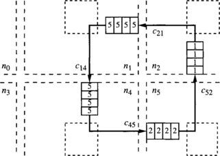
Note that a configuration describes the state of an interconnection network at a given time. Thus, we do not need to consider configurations describing impossible situations. A configuration is legal if it describes a possible situation. In particular, we should not consider configurations in which buffer capacity is exceeded. Also, a packet cannot occupy a given channel unless the routing function supplies it for the packet destination. Figure 3.3 shows an illegal configuration for the above-defined routing function R because a packet followed a nonminimal path, and R only forwards packets following minimal paths.
In summary, a canonical deadlocked configuration is a legal configuration in which no packet can advance. If SAF or VCT switching is used:
![]() No packet has already arrived at its destination node.
No packet has already arrived at its destination node.
![]() Packets cannot advance because the queues for all the alternative output channels supplied by the routing function are full.
Packets cannot advance because the queues for all the alternative output channels supplied by the routing function are full.
If wormhole switching is used:
![]() There is no packet whose header flit has already arrived at its destination.
There is no packet whose header flit has already arrived at its destination.
![]() Header flits cannot advance because the queues for all the alternative output channels supplied by the routing function are not empty (remember, we make the assumption that a queue cannot contain flits belonging to different packets).
Header flits cannot advance because the queues for all the alternative output channels supplied by the routing function are not empty (remember, we make the assumption that a queue cannot contain flits belonging to different packets).
![]() Data flits cannot advance because the next channel reserved by their packet header has a full queue. Note that a data flit can be blocked at a node even if there are free output channels to reach its destination because data flits must follow the path reserved by their header.
Data flits cannot advance because the next channel reserved by their packet header has a full queue. Note that a data flit can be blocked at a node even if there are free output channels to reach its destination because data flits must follow the path reserved by their header.
In some cases, a configuration cannot be reached by routing packets starting from an empty network. This situation arises when two or more packets require the use of the same channel at the same time to reach the configuration. A configuration that can be reached by routing packets starting from an empty network is reachable or routable [63]. It should be noted that by defining the domain of the routing function as N × N, every legal configuration is also reachable. Effectively, as the routing function has no memory of the path followed by each packet, we can consider that, for any legal configuration, a packet stored in a channel queue was generated by the source node of that channel. In wormhole switching, we can consider that the packet was generated by the source node of the channel containing the last flit of the packet. This is important because when all the legal configurations are reachable, we do not need to consider the dynamic evolution of the network leading to those configurations. We can simply consider legal configurations, regardless of the packet injection sequence required to reach them. When all the legal configurations are reachable, a routing function is deadlock-free if and only if there is not any deadlocked configuration for that routing function.
A routing function R is connected if it is able to establish a path between every pair of nodes x and y using channels belonging to the sets supplied by R. It is obvious that a routing function must be connected, and most authors implicitly assume this property. However, we mention it explicitly because we will use a restricted routing function to prove deadlock freedom, and restricting a routing function may disconnect it.
3.1.3 Necessary and Sufficient Condition
The theoretical model of deadlock avoidance we are going to present relies on the concept of channel dependency [77]. Other approaches are possible. They will be briefly described in Section 3.3. When a packet is holding a channel, and then it requests the use of another channel, there is a dependency between those channels. Both channels are in one of the paths that may be followed by the packet. If wormhole switching is used, those channels are not necessarily adjacent because a packet may hold several channels simultaneously. Also, at a given node, a packet may request the use of several channels, then select one of them (adaptive routing). All the requested channels are candidates for selection. Thus, every requested channel will be selected if all the remaining channels are busy. Also, in our router model, when all the alternative output channels are busy, the packet will get the first requested channel that becomes available. So, all the requested channels produce dependencies, even if they are not selected in a given routing operation.
The behavior of packets regarding deadlock is different depending on whether there is a single or several routing choices at each node. With deterministic routing, packets have a single routing option at each node. Consider a set of packets such that every packet in the set has reserved a channel and it requests a channel held by another packet in the set. Obviously, that channel cannot be granted, and that situation will last forever. Thus, it is necessary to remove all the cyclic dependencies between channels to prevent deadlocks [77], as shown in the next example. This example will be revisited in Chapter 4.
Consider a unidirectional ring with four nodes denoted ni, i = {0, 1, 2, 3}, and a unidirectional channel connecting each pair of adjacent nodes. Let ci, i = {0, 1, 2, 3}, be the outgoing channel from node ni. In this case, it is easy to define a connected routing function. It can be stated as follows: If the current node ni is equal to the destination node nj, store the packet. Otherwise, use ci, ∀j ≠ i. Figure 3.4(a) shows the network. There is a cyclic dependency between ci channels. Effectively, a packet at node n0 destined for n2 can reserve c0 and then request c1. A packet at node n1 destined for n3 can reserve c1 and then request c2. A packet at node n2 destined for n0 can reserve c2 and then request c3. Finally, a packet at node n3 destined for n1 can reserve c3 and then request c0. It is easy to see that a configuration containing the above-mentioned packets is deadlocked because every packet has reserved one channel and is waiting for a channel occupied by another packet.
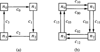
Figure 3.4 Networks for Example 3.2: (a) unidirectional ring and (b) unidirectional ring with two virtual channels per physical channel.
Now consider that every physical channel ci is split into two virtual channels, c0i and c1i, as shown in Figure 3.4(b). The new routing function can be stated as follows: If the current node ni is equal to the destination node nj, store the packet. Otherwise, use c0i if j < i, or c1i if j > i. As can be seen, the cyclic dependency has been removed because after using channel c03, node n0 is reached. Thus, all the destinations have a higher index than n0, and it is not possible to request c00. Note that channels c00 and c13 are never used. Also, the new routing function is deadlock-free. Let us show that there is not any deadlocked configuration by trying to build one. If there were a packet stored in the queue of channel c12, it would be destined for n3 and flits could advance. So c12 must be empty. Also, if there were a packet stored in the queue of c11, it would be destined for n2 or n3. As c12 is empty, flits could also advance and c11 must be empty. If there were a packet stored in the queue of c10, it would be destined for n1, n2, or n3. As c11 and c12 are empty, flits could advance and c10 must be empty. Similarly, it can be shown that the remaining channels can be emptied.
When adaptive routing is considered, packets usually have several choices at each node. Even if one of those choices is a channel held by another packet, other routing choices may be available. Thus, it is not necessary to eliminate all the cyclic dependencies, provided that every packet can always find a path toward its destination whose channels are not involved in cyclic dependencies. This is shown in the next example.
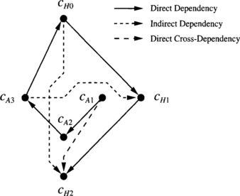
Consider a unidirectional ring with four nodes denoted ni, i = {0, 1, 2, 3}, and two channels connecting each pair of adjacent nodes, except nodes n3 and n0 that are linked by a single channel. Let cAi, i = {0, 1, 2, 3}, and cHi, i = {0, 1, 2}, be the outgoing channels from node ni. The routing function can be stated as follows: If the current node ni is equal to the destination node nj, store the packet. Otherwise, use either cAi, j ∀ j ≠ i, or cHi,∀j > i. Figure 3.5 shows the network.
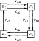
Figure 3.5 Network for Example 3.3.
There are cyclic dependencies between cAi channels. Effectively, a packet at node n0 destined for n2 can reserve cA0 and then request cA1 and cH1. A packet at node n1 destined for n3 can reserve cA1 and then request cA2 and cH2. A packet at node n2 destined for n0 can reserve cA2 and then request cA3. Finally, a packet at node n3 destined for n1 can reserve cA3 and then request cA0 and cH0.
However, the routing function is deadlock-free. Although we focus on wormhole switching, the following analysis is also valid for other switching techniques. Let us show that there is not any deadlocked configuration by trying to build one. If there were a packet stored in the queue of channel cH2, it would be destined for n3 and flits could advance. So, cH2 must be empty. Also, if there were a packet stored in the queue of cH1, it would be destined for n2 or n3. As cH2 is empty, flits could also advance and cH1 must be empty. If there were flits stored in the queue of cH0, they would be destined for n1, n2, or n3. Even if their header were stored in cA1 or cA2, as cH1 and cH2 are empty, flits could advance and cH0 must be empty.
Thus, any deadlocked configuration can only use channels cAi. Although there is a cyclic dependency between them, cA0 cannot contain flits destined for n0. That configuration would not be legal because n0 cannot forward packets for itself through the network. For any other destination, those flits can advance because cH1 and cH2 are empty. Again, cA0 can be emptied, thus breaking the cyclic dependency. Thus, the routing function is deadlock-free.
Example 3.3 shows that deadlocks can be avoided even if there are cyclic dependencies between some channels. Obviously, if there were cyclic dependencies between all the channels in the network, there would be no path to escape from cycles. Thus, the key idea consists of providing a path free of cyclic dependencies to escape from cycles. That path can be considered as an escape path. Note that at least one packet from each cycle should be able to select the escape path at the current node, whichever its destination is. In Example 3.3, for every legal configuration, a packet whose header flit is stored in channel cA0 must be destined for either n1, n2, or n3. In the first case, it can be immediately delivered. In the other cases, it can use channel cH1.
It seems that we could focus only on the escape paths and forget about the other channels to prove deadlock freedom. In order to do so, we can restrict a routing function in such a way that it only supplies channels belonging to the escape paths as routing choices. In other words, if a routing function supplies a given set of channels to route a packet from the current node toward its destination, the restricted routing function will supply a subset of those channels. The restricted routing function will be referred to as a routing subfunction. Formally, if R is a routing function and R1 is a routing subfunction of R, we have
Channels supplied by R1 for a given packet destination will be referred to as escape channels for that packet. Note that the routing subfunction is only a mathematical tool to prove deadlock freedom. Packets can be routed by using all the channels supplied by the routing function R. Simply, the concept of a routing subfunction will allow us to focus on the set of escape channels. This set is C1 = ∪∀x,y∈N R1(x, y).
When we restrict our attention to escape channels, it is important to give an accurate definition of channel dependency because there are some subtle cases. There is a channel dependency from an escape channel ci to another escape channel ck if there exists a packet that is holding ci and it requests ck as an escape channel for itself. It does not matter whether ci is an escape channel for this packet, as far as it is an escape channel for some other packets. Also, it does not matter whether ci and ck are adjacent or not. These cases will be analyzed in Sections 3.1.4 and 3.1.5.
Channel dependencies can be grouped together to simplify the analysis of deadlocks. A convenient form is the channel dependency graph [77]. It is a directed graph, D = G(C, E). The vertices of D are the channels of the interconnection network I. The arcs of D are the pairs of channels (ci, cj) such that there is a channel dependency from ci to cj. As indicated above, we can restrict our attention to a subset of channels C1 ⊂ C, thus defining a channel dependency graph in which all the vertices belong to C1. That graph has been defined as the extended channel dependency graph of R1 [92, 97]. The word “extended” means that although we are focusing on a channel subset, packets are allowed to use all the channels in the network.
The extended channel dependency graph is a powerful tool to analyze whether a routing function is deadlock-free or not. The following theorem formalizes the ideas presented in Example 3.3 by proposing a necessary and sufficient condition for a routing function to be deadlock-free [92, 97]. This theorem is only valid under the previously mentioned assumptions.
For adaptive routing functions, the application of Theorem 3.1 requires the definition of a suitable routing subfunction. This is not an easy task. Intuition and experience help considerably. A rule of thumb that usually works consists of looking at deterministic deadlock-free routing functions previously proposed for the same topology. If one of those routing functions is a restriction of the routing function we are analyzing, we can try it. As we will see in Chapter 4, a simple way to propose adaptive routing algorithms follows this rule in the opposite way. It starts from a deterministic deadlock-free routing function, adding channels in a regular way. The additional channels can be used for fully adaptive routing.
Theorem 3.1 is valid for SAF, VCT, and wormhole switching under the previously mentioned assumptions. The application to each switching technique will be presented in Sections 3.1.4 and 3.1.5. For wormhole switching, the condition proposed by Theorem 3.1 becomes a sufficient one if the routing function is not coherent. Thus, it is still possible to use this theorem to prove deadlock freedom on incoherent routing functions, as can be seen in Exercise 3.3.
Finally, when a packet uses an escape channel at a given node, it can freely use any of the available channels supplied by the routing function at the next node. It is not necessary to restrict that packet to use only channels belonging to the escape paths. Also, when a packet is blocked because all the alternative output channels are busy, the header is not required to wait on any predetermined channel. Instead, it waits in the input channel queue. It is repeatedly routed until any of the channels supplied by the routing function becomes free. Both issues are important because they considerably increase routing flexibility, especially when the network is heavily loaded.
3.1.4 Deadlock Avoidance in SAF and VCT Switching
In this section, we restrict our attention to SAF and VCT switching. Note that dependencies arise because a packet is holding a resource while requesting another one. Although VCT pipelines packet transmission, it behaves in the same way as SAF regarding deadlock because packets are buffered when they are blocked. A blocked packet is buffered into a single channel. Thus, dependencies only exist between adjacent channels.
According to expression (3.1), it is possible to restrict a routing function in such a way that a channel ci supplied by R for destination nodes x and y is only supplied by the routing subfunction R1 for destination node x. In this case, ci is an escape channel for packets destined for x but not for packets destined for y.
As indicated in Section 3.1.3, there is a channel dependency from an escape channel ci to another escape channel ck if there exists a packet that is holding ci and it requests ck as an escape channel for itself. If ci is also an escape channel for the packet destination, we refer to this kind of channel dependency as direct dependency [86, 91]. If ci is not an escape channel for the packet destination, the dependency is referred to as direct cross-dependency [92, 97]. Direct cross-dependencies must be considered because a packet may be holding a channel needed by another packet to escape from cycles. The following example shows both kinds of dependency.
Let us consider again the routing function R defined in Example 3.3, in order to show how the general theory can be applied to SAF and VCT switching.
A well-known deterministic deadlock-free routing function for the ring was proposed in [77]. It requires two virtual channels per physical channel. One of those channels is used when the destination node has a higher label than the current node. The other channel is used when the destination has a lower label. This routing function is a restriction of the routing function proposed in Example 3.3. Instead of allowing cAi channels to be used for all the destinations, they are only used when the destination is lower than the current node. Let us define the routing subfunction R1 more formally: If the current node ni is equal to the destination node nj, store the packet. Otherwise, use cAi if j < i, or cHi if j > i
Figure 3.6 shows the extended channel dependency graph for R1 when SAF switching is used. As will be seen, the graph for wormhole switching is different. Black circles represent the unidirectional channels supplied by R1. Arcs represent channel dependencies. This notation will be used in all the drawings of channel dependency graphs. Note that the graph only considers the channels supplied by R1. In particular, cA0 is not a node of the graph.
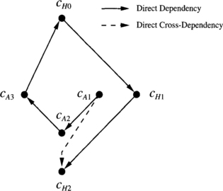
A packet destined for n2 that is currently stored at n0 can use cH0 to reach n1 and then cH1 to reach n2. After reaching n1, it is holding a buffer from cH0 and it requests cH1. Thus, there is a direct dependency from cH0 to cH1 because both channels are supplied by the routing subfunction for the packet destination. Similarly, there is a direct dependency from cH1 to cH2.
A packet destined for n0 that is currently stored at n1 can use cA1 to reach n2, then cA2 to reach n3, and then cA3 to reach n0. Thus, there are direct dependencies from cA1 to cA2 and from cA2 to cA3. Finally, a packet destined for n1 that is currently stored at n3 can use cA3 to reach n0, and then cH0 to reach n1.
Once again, both channels are supplied by the routing subfunction for the packet destination, and there is a direct dependency from cA3 to cH0.
Now consider a packet destined for n3 that is currently stored at n1. It can use cA1 and cH2 to reach node n3 because both channels are supplied by R. Although cA1 is not supplied by R1 for the packet destination, it is supplied by R1 for other destinations. Thus, there is a direct cross-dependency from cA1 to cH2.
The routing subfunction R1 is obviously connected. Packets use either cAi or cHi channels depending on whether the destination node is lower or higher than the current node. As there are no cycles in the graph, we can conclude that R is deadlock-free.
In Example 3.4, direct cross-dependencies do not produce any cycle. In some cases, if direct cross-dependencies were not considered, you could erroneously conclude that the routing function is deadlock-free. See Exercise 3.1 for an example. The channel dependency graph and the extended channel dependency graph of a routing subfunction would be identical if direct cross-dependencies were not considered. There are some cases in which direct cross-dependencies do not exist. Remember that direct cross-dependencies exist because some channels are used as escape channels or not depending on packet destination. We can define a routing subfunction R1 by using a channel subset C1, according to the following expression:
In this case, a channel belonging to C1 is used as an escape channel for all the destinations for which it can be supplied by R. Thus, there is not any direct cross-dependency between channels in C1. As a consequence, the channel dependency graph and the extended channel dependency graph of a routing subfunction are identical, supplying a simple condition to check whether a routing function is deadlock-free. This condition is proposed by the following corollary [86]. Note that it only supplies a sufficient condition.
This theorem indicates that we can start from a connected deadlock-free routing function R1, adding as many channels as we wish. The additional channels can be used in any way, following either minimal or nonminimal paths. The resulting routing function will be deadlock-free. The only restriction is that we cannot add routing options to the channels initially used by R1.2 Corollary 3.2 and Theorem 3.2 are valid for SAF and VCT switching, but not for wormhole switching. The following example shows the application of Theorem 3.2.
3.1.5 Deadlock Avoidance in Wormhole Switching
Wormhole switching pipelines packet transmission. The main difference with respect to VCT regarding deadlock avoidance is that when a packet is blocked, flits remain in the channel buffers. Remember that when a packet is holding a channel and it requests another channel, there is a dependency between them. As we assume no restrictions for packet length, packets will usually occupy several channels when blocked. Thus, there will exist channel dependencies between nonadjacent channels. Of course, the two kinds of channel dependencies defined for SAF and VCT switching are also valid for wormhole switching.
Dependencies between nonadjacent channels are not important when all the channels of the network are considered because they cannot produce cycles. Effectively, a packet holding a channel and requesting a nonadjacent channel is also holding all the channels in the path it followed from the first channel up to the channel containing its header. Thus, there is also a sequence of dependencies between the adjacent channels belonging to the path reserved by the packet. The information offered by the dependency between nonadjacent channels is redundant.
However, the application of Theorem 3.1 requires the definition of a routing subfunction in such a way that the channels supplied by it could be used as escape channels from cyclic dependencies. When we restrict our attention to the escape channels, it may happen that a packet reserved a set of adjacent channels ci, ci+1, …, ck–1, ck in such a way that Ci and Ck are escape channels but ci+1, …, ck–1 are not. In this case, the dependency from Ci to Ck is important because the information offered by it is not redundant. If ci is an escape channel for the packet destination, we will refer to this kind of channel dependency as indirect dependency [86]. If ci is not an escape channel for the packet destination but is an escape channel for some other destinations, the dependency is referred to as indirect cross-dependency [92, 97]. In both cases, the channel ck requested by the packet must be an escape channel for it. Indirect cross-dependencies are the indirect counterpart of direct cross-dependencies. To illustrate these dependencies, we present another example.
Consider a unidirectional ring using wormhole switching with six nodes denoted ni, i = {0, 1, 2, 3, 4, 5}, and three channels connecting each pair of adjacent nodes. Let cAi, cBi, and cHi, i = {0, 1, 2, 3, 4, 5}, be the outgoing channels from node ni. The routing function can be stated as follows: If the current node ni is equal to the destination node nj, store the packet. Otherwise, use either cAi or cBi,∀ j ≠ i, or cHi,∀j > i. This routing function is identical to the one for Example 3.4, except that cBi channels have been added. Figure 3.7 shows the network.
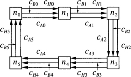
Figure 3.7 Network for Example 3.6.
Suppose that we define a routing subfunction in the same way as in Example 3.4: cAi channels are supplied by the routing subfunction when the packet destination is lower than the current node. cHi channels are always supplied by the routing subfunction. Consider a packet destined for n4 whose header is at n1. It can use channels cH1, cB2, and cH3 to reach n4. Thus, while the packet is holding cH1 and cB2 it requests cH3. As cB2 is not an escape channel, there is an indirect dependency from cH1 to cH3. Again, consider the packet destined for n4 whose header is at n1. It can use channels cA1, cB2, and cH3 to reach n4. As cA1 is not an escape channel for the packet destination but is an escape channel for some other destinations, it produces an indirect cross-dependency from cA1 to cH3. The same packet can also use channels cA1, cA2, and cA3, again producing an indirect cross-dependency from cA1 to cH3. But in this case, it also produces a direct cross-dependency from cA2 to cH3.
We have defined several kinds of channel dependencies, showing examples for all of them. Except for direct dependencies, all kinds of channel dependencies arise because we restrict our attention to a routing subfunction (the escape channels). Defining several kinds of channel dependencies allowed us to highlight the differences between SAF and wormhole switching. However, it is important to note that all kinds of channel dependencies are particular cases of the definition given in Section 3.1.3. Now let us revisit Example 3.3 to show how Theorem 3.1 is applied to networks using wormhole switching.
Consider once again the unidirectional ring and the routing function R defined in Example 3.3. We are going to use the same routing subfunction R1 defined in Example 3.4. It can be stated as follows: If the current node ni is equal to the destination node nj, store the packet. Otherwise, use cAi if j < i, or cHi if j > i.
Figure 3.8 shows the extended channel dependency graph for R1 when wormhole switching is used. Direct dependencies and direct cross-dependencies are the same as in Example 3.4. Let us analyze indirect dependencies. Consider a packet destined for n2 whose header is at n3. It can use cA3, cA0, and cH1 to reach n2. There is an indirect dependency from cA3 to cH1 because cA3 and cH1 are supplied by the routing subfunction for the packet destination. However, cA0 is not supplied by the routing subfunction for the packet destination. Now consider a packet destined for n3 whose header is at n0. It can use cH0, cA1, and cH2 to reach n3. Thus, there is an indirect dependency from cH0 to cH2. In this example, there is not any indirect cross-dependency between channels. As there are no cycles in the graph, the routing function R is also deadlock-free under wormhole switching.
In wormhole switching, a packet usually occupies several channels when blocked. As a consequence, there are many routing functions that are deadlock-free under SAF, but they are not when wormhole switching is used. See Exercise 3.2 for an example.
Note that Theorem 3.1 does not require that all the connected routing subfunctions have an acyclic extended channel dependency graph to guarantee deadlock freedom. So the existence of cycles in the extended channel dependency graph for a given connected routing subfunction does not imply the existence of deadlocked configurations. It would be necessary to try all the connected routing subfunctions. If the graphs for all of them have cycles, then we can conclude that there are deadlocked configurations. Usually it is not necessary to try all the routing subfunctions. If a reasonably chosen routing subfunction has cycles in its extended channel dependency graph, we can try to form a deadlocked configuration by filling one of the cycles, as shown in Exercise 3.2.
The next example presents a fully adaptive minimal routing algorithm for 2-D meshes. It can be easily extended to n-dimensional meshes. This algorithm is simple and efficient. It is the basic algorithm currently implemented in the Reliable Router [74] to route packets in the absence of faults.
Consider a 2-D mesh using wormhole switching. Each physical channel ci has been split into two virtual channels, namely, ai and bi. The routing function R supplies all the a channels belonging to a minimal path. It also supplies one b channel according to dimension-order routing (XY routing algorithm).4 Figure 3.9 shows a routing example. Arrows show all the alternative paths that can be followed by a packet traveling from node 0 to node 10. Note that both a and b channels can be used to go from node 0 to node 1. However, only the a channel can be used if the packet is sent across the Y dimension at node 0.
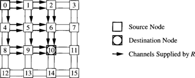
Figure 3.9 Routing example for R (defined in Example 3.8).
Let C1 be the set of b channels. Consider the routing subfunction R1 defined by C1 according to expression (3.2). It is the XY routing algorithm. It is connected because every destination can be reached using dimension-order routing. Figure 3.10 shows part of the extended channel dependency graph for R1 on a 3 × 3 mesh. Black circles represent the unidirectional channels belonging to C1. They are labeled as bij, where i and j are the source and destination nodes, respectively. As a reference, channels are also represented by thin lines. Arcs (thick lines with arrows) represent channel dependencies, dashed arcs corresponding to indirect dependencies. For the sake of clarity, we have removed all the indirect dependencies that do not add information to the graph. In particular, the indirect dependencies that can be obtained by composing two or more direct or indirect dependencies have been removed. As R1 has been defined according to expression (3.2), there is not any cross-dependency. It can be seen that the graph is acyclic. Thus, R is deadlock-free.
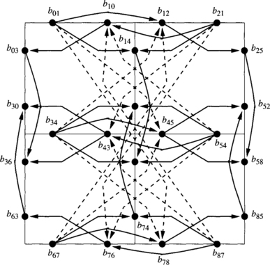
Figure 3.10 Extended channel dependency graph for R1 (defined in Example 3.8).
4The Reliable Router uses two virtual channels for fully adaptive minimal routing and two virtual channels for dimension-order routing in the absence of faults.
Some nonminimal routing functions may not be coherent. As mentioned in Section 3.1.3, Theorem 3.1 can also be applied to prove deadlock freedom on incoherent routing functions (see Exercise 3.3). However, Theorem 3.1 only supplies a sufficient condition if the routing function is not coherent. Thus, if there is no routing subfunction satisfying the conditions proposed by Theorem 3.1, we cannot conclude that it is not deadlock-free (see Exercise 3.4). Fortunately, incoherent routing functions that cannot be proved to be deadlock-free by using Theorem 3.1 are very rare.
The reason why Theorem 3.1 becomes a sufficient condition is that incoherent routing functions allow packets to cross several times through the same node. If a packet is long enough, it may happen that it is still using an output channel from a node when it requests again an output channel from the same node. Consider again the definition of channel dependency. The packet is holding an output channel and it requests several output channels, including the one it is occupying. Thus, there is a dependency from the output channel occupied by the packet to itself, producing a cycle in the channel dependency graph. However, the selection function will never select that channel because it is busy.
A theoretical solution consists of combining routing and selection functions into a single function in the definition of channel dependency. Effectively, when a packet long enough using wormhole switching crosses a node twice, it cannot select the output channel it reserved the first time because it is busy. The dependency from that channel to itself no longer exists. With this new definition of channel dependency, Theorem 3.1 would also be a necessary and sufficient condition for deadlock-free routing in wormhole switching. However, the practical interest of this extension is very small. As mentioned above, incoherent routing functions that cannot be proved to be deadlock-free by using Theorem 3.1 are very rare. Additionally, including the selection function in the definition of channel dependency implies a dynamic analysis of the network because the selection function considers channel status. We will present alternative approaches to consider incoherent routing functions in Section 3.3.
3.2 Extensions
In this section we extend the theory presented in Section 3.1 by proposing methods to simplify its application as well as by considering alternative definitions of the routing function.
3.2.1 Channel Classes
Theorem 3.1 proposes the existence of an acyclic graph as a condition to verify deadlock freedom. As the graph indicates relations between some channels, the existence of an acyclic graph implies that an ordering can be defined between those channels. It is possible to define a total ordering between channels in most topologies [77]. However, the relations in the graph only supply information to establish a partial ordering in all but a few simple cases, like unidirectional rings.
Consider two unrelated channels ci, cj that have some common predecessors and successors in the ordering. We can say that they are at the same level in the ordering or that they are equivalent. This equivalence relation groups equivalent channels so that they form an equivalence class [89]. Note that there is no dependency between channels belonging to the same class. Now, it is possible to define the concept of class dependency. There is a dependency from class Ki to class Kj if there exist two channels ci ∈ Ki and cj ∈ Kj such that there is a dependency from ci to cj. We can represent class dependencies by means of a graph. If the classes contain all the channels, we define the class dependency graph. If we restrict our attention to classes formed by the set of channels C1 supplied by a routing subfunction R1, we define the extended class dependency graph [89].
Theorem 3.1 can be restated by using the extended class dependency graph instead of the extended channel dependency graph.
The existence of a dependency between two classes does not imply the existence of a dependency between every pair of channels in those classes. Thus, the existence of cycles in the extended class dependency graph does not imply that the extended channel dependency graph has cycles. As a consequence, Theorem 3.3 only supplies a sufficient condition. However, this is enough to prove deadlock freedom.
It is not always possible to establish an equivalence relation between channels. However, when possible, it considerably simplifies the analysis of deadlock freedom. The channels that can be grouped into the same class usually have some common topological properties, for instance, channels crossing the same dimension of a hypercube in the same direction. Classes are not a property of the topology alone. They also depend on the routing function. The next example shows the definition of equivalence classes in a 2-D mesh.
Consider the extended channel dependency graph drawn in Figure 3.10. There is not any dependency between channels b01, b34, and b67. However, there are dependencies from b01, b34, and b67, to b12, b45, and b78. Channels b01, b34, and b67, can be grouped into the same class. The same can be done with channels b12, b45, and b78. Suppose that we define classes such that all the horizontal (vertical) channels in the same column (row) and direction are in the same class. It is easy to see that there is not any dependency between channels belonging to the same class. Let us denote the classes containing east (X-positive) channels as X0+, X1+, starting from the left. For instance, X0+ = {b01, b34, b67}. Similarly, classes containing west channels are denoted as X0–, X1–, starting from the right. Also, classes containing north channels are denoted as Y0+, Y1+, starting from the bottom, and classes containing south channels are denoted as Y0–, Y1–, starting from the top. Figure 3.11 shows the extended class dependency graph corresponding to the extended channel dependency graph shown in Figure 3.10.
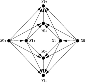
Figure 3.11 Extended class dependency graph for R1 (defined in Example 3.8).
Note that there are class dependencies from each X class to each Y class. This is because there is at least one horizontal channel from which it is possible to request the corresponding vertical channel. As can be seen, the extended class dependency graph is much simpler than the extended channel dependency graph. However, it supplies the same information about the absence of cyclic dependencies.
As mentioned above, classes depend on the routing function. Exercise 3.5 shows a routing function for the 2-D mesh for which classes are formed by channels in the same diagonal.
3.2.2 Extending the Domain of the Routing Function
In Section 3.1.2 we defined the domain of the routing function as N × N. Thus, routing functions only considered the current and destination nodes to compute the routing options available to a given packet. It is possible to extend the domain of the routing function by considering more information. For instance, a packet can carry the address of its source node in its header. Also, packets can record some history information in the header, like the number of misrouting operations performed. Carrying additional information usually produces some overhead, unless header flits have enough bits to accommodate the additional information.
It is also possible to use additional local information to compute the routing function. The most interesting one is the input channel queue in which the packet header (or the whole packet) is stored. The use of this information does not produce a noticeable overhead. However, it allows a higher flexibility in the definition of routing functions. Their domain is now defined as C × N; that is, the routing function takes into account the input channel and the destination node.
Including the input channel in the domain of the routing function implies that some deadlocked configurations may be unreachable [309]. So, the existence of a deadlocked configuration does not imply that deadlock can occur because all the deadlocked configurations may be unreachable. However, up to now, nobody has proposed unreachable deadlocked configurations for the most common topologies. So, for practical applications, we can assume that all the configurations are reachable. As a consequence, Theorem 3.1 remains valid for routing functions defined on C × N. Moreover, even if some deadlocked configurations are not reachable, the sufficient condition of Theorem 3.1 is valid. So, for practical applications, this theorem can be used to prove deadlock freedom on routing functions defined on C × N, regardless of the existence of unreachable deadlocked configurations. On the other hand, Theorem 3.2 is only valid for routing functions defined on N × N.
3.2.3 Central Queues
For the sake of clarity, in Section 3.1 we only considered routing functions using edge buffers. However, most routing functions proposed up to now for SAF switching use central queues. In this case, a few central buffers deep enough to store one or more packets are used. The router model was described in Section 3.1.1.
Let Q be the set of all the queues in the system. The node containing a queue qi is denoted ni. When routing a packet at queue qi, instead of supplying a set of channels, the routing function supplies a set of queues belonging to nodes adjacent to ni. It may take into account the current and destination nodes of the packet. In this case, the domain of the routing function is N × N. Alternatively, the routing function may consider the current queue and the destination node. In this case, its domain is Q × N. Note that this routing function is distinct as there may be multiple queues per node.
Now, central queues are the shared resources. We used channel dependencies to analyze the use of edge buffers. Similarly, we can use queue dependencies to analyze deadlocks arising from the use of central queues. There is a queue dependency between two central queues when a packet is totally or partially stored in one of them and it requests the other one. All the definitions given for edge buffers have their counterpart for central queues. In particular, queue dependency graphs replace channel dependency graphs. Also, instead of restricting the use of channels, a routing subfunction restricts the use of queues. With these changes in notation, the results presented in Section 3.1 for routing functions defined on N × N are also valid for routing functions defined on N × N that use central queues. Also, those results can be applied to routing functions defined on Q × N, supplying only a sufficient condition for deadlock freedom as mentioned in Section 3.2.2.
We can generalize the results for edge buffers and central queues by mixing both kinds of resources [10]. It will be useful in Section 3.6. A resource is either a channel or a central queue. Note that we only consider the resources that can be held by a packet when it is blocked. Thus, there is a resource dependency between two resources when a packet is holding one of them and it requests the other one. Once again, the definitions and theoretical results proposed for edge buffers have their counterpart for resources. All the issues, including coherency and reachability, can be considered in the same way as for edge buffers. In particular, Theorem 3.1 can be restated simply by replacing the extended channel dependency graph by the extended resource dependency graph. Note that the edge buffer or central queue containing the packet header is usually required in the domain of the routing function to determine the kind of resource being used by the packet. So, strictly speaking, the resulting theorem would only be a sufficient condition for deadlock freedom, as mentioned in Section 3.2.2. Note that this generalized result is valid for all the switching techniques considered in Section 3.1.
3.3 Alternative Approaches
There are alternative approaches to avoid deadlocks. Some of them are theoretical approaches based on other models. Other approaches are simple and effective tricks to avoid deadlocks. These tricks do not work for all switching techniques.
3.3.1 Theoretical Approaches
The theory presented in Section 3.1 relies on the concept of channel dependency or resource dependency. However, some authors used different tools to analyze deadlocks. The most interesting one is the concept of waiting channel [207]. The basic idea is the same as for channel dependency: a packet is holding some channel(s) while waiting for other channel(s). The main difference with respect to channel dependency is that waiting channels are not necessarily the same channels offered by the routing function to that packet. More precisely, if the routing function supplies a set of channels Ci to route a packet in the absence of contention, the packet only waits for a channel belonging to Cj ⊆ Ci when it is blocked. The subset Cj may contain a single channel. In other words, if a packet is blocked, the number of routing options available to that packet may be reduced. This is equivalent to dynamically changing the routing function depending on packet status.
By reducing the number of routing options when a packet is blocked, it is possible to allow more routing flexibility in the absence of contention [73]. In fact, some routing options that may produce deadlock are forbidden when the packet is blocked. Remember that deadlocks arise because some packets are holding resources while waiting for other resources in a cyclic way. If we prevent packets from waiting on some resources when blocked, we can prevent deadlocks. However, the additional routing flexibility offered by this model is usually small.
Models based on waiting channels are more general than the ones based on channel dependencies. In fact, the latter are particular cases of the former when a packet is allowed to wait on all the channels supplied by the routing function. Another particular case of interest arises when a blocked packet always waits on a single channel. In this case, this model matches the behavior of routers that buffer blocked packets in queues associated with output channels. Note that those routers do not use wormhole switching because they buffer whole packets.
Although models based on waiting channels are more general than the ones based on channel dependencies, note that adaptive routing is useful because it offers alternative paths when the network is congested. In order to maximize performance, a blocked packet should be able to reserve the first valid channel that becomes available. Thus, restricting the set of routing options when a packet is blocked does not seem to be an attractive choice from the performance point of view.
A model that increases routing flexibility in the absence of contention is based on the wait-for graph [73]. This graph indicates the resources that blocked packets are waiting for. Packets are even allowed to use nonminimal paths as long as they are not blocked. However, blocked packets are not allowed to wait for channels held by other packets in a cyclic way. Thus, some blocked packets are obliged to use deterministic routing until delivered if they produce a cycle in the wait-for graph.
An interesting model based on waiting channels is the message flow model [207, 209]. In this model, a routing function is deadlock-free if and only if all the channels are deadlock-immune. A channel is deadlock-immune if every packet that reserves that channel is guaranteed to be delivered. The model starts by analyzing the channels for which a packet reserving them is immediately delivered. Those channels are deadlock-immune. Then the model analyzes the remaining channels step by step. In each step, the channels adjacent to the ones considered in the previous step are analyzed. A channel is deadlock-immune if for all the alternative paths a packet can follow, the next channel to be reserved is also deadlock-immune. Waiting channels play a role similar to routing subfunctions, serving as escape paths when a packet is blocked.
Another model uses a channel waiting graph [309]. This graph captures the relationship between channels in the same way as the channel dependency graph. However, this model does not distinguish between routing and selection functions. Thus, it considers the dynamic evolution of the network because the selection function takes into account channel status. Two theorems are proposed. The first one considers that every packet has a single waiting channel. It states that a routing algorithm is deadlock-free if it is wait-connected and there are no cycles in the channel waiting graph. The routing algorithm is wait-connected if it is connected by using only waiting channels.
But the most important result is a necessary and sufficient condition for deadlock-free routing. This condition assumes that a packet can wait on any channel supplied by the routing algorithm. It uses the concept of true cycles. A cycle is a true cycle if it is reachable, starting from an empty network. The theorem states that a routing algorithm is deadlock-free if and only if there exists a restricted channel waiting graph that is wait-connected and has no true cycles [309]. This condition is valid for incoherent routing functions and for routing functions defined on C × N. However, it proposes a dynamic condition for deadlock avoidance, thus requiring the analysis of all the packet injection sequences to determine whether a cycle is reachable (true cycle). True cycles can be identified by using the algorithm proposed in [309]. This algorithm has nonpolynomial complexity. When all the cycles are true cycles, this theorem is equivalent to Theorem 3.1. The theory proposed in [309] has been generalized in [307], supporting SAF, VCT, and wormhole switching. Basically, the theory proposed in [307] replaces the channel waiting graph by a buffer waiting graph.
Up to now, nobody has proposed static necessary and sufficient conditions for deadlock-free routing for incoherent routing functions and for routing functions defined on C × N. This is a theoretical open problem. However, as mentioned in previous sections, it is of very little practical interest because the cases where Theorem 3.1 cannot be applied are very rare. Remember that this theorem can be used to prove deadlock freedom for incoherent routing functions and for routing functions defined on C × N. In these cases it becomes a sufficient condition.
3.3.2 Deflection Routing
Unlike wormhole switching, SAF and VCT switching provide more buffer resources when packets are blocked. A single central or edge buffer is enough to store a whole packet. As a consequence, it is much simpler to avoid deadlock.
A simple technique, known as deflection routing [137] or hot potato routing, is based on the following idea: the number of input channels is equal to the number of output channels. Thus, an incoming packet will always find a free output channel.
The set of input and output channels includes memory ports. If a node is not injecting any packet into the network, then every incoming packet will find a free output channel. If several options are available, a channel belonging to a minimal path is selected. Otherwise, the packet is misrouted. If a node is injecting a packet into the network, it may happen that all the output channels connecting to other nodes are busy. The only free output channel is the memory port. In this case, if another packet arrives at the node, it is buffered. Buffered packets are reinjected into the network before injecting any new packet at that node.
Deflection routing has two limitations. First, it requires storing the packet into the current node when all the output channels connecting to other nodes are busy. Thus, it cannot be applied to wormhole switching. Second, when all the output channels belonging to minimal paths are busy, the packet is misrouted. This increases packet latency and bandwidth consumption, and may produce livelock. The main advantages are its simplicity and flexibility. Deflection routing can be used in any topology, provided that the number of input and output channels per node is the same.
Deflection routing was initially proposed for communication networks. It has been shown to be a viable alternative for networks using VCT switching. Misrouting has a small impact on performance [188]. Livelock will be analyzed in Section 3.7.
3.3.3 Injection Limitation
Another simple technique to avoid deadlock consists of restricting packet injection. Again, it is only valid for SAF and VCT switching. This technique was proposed for rings [298]. Recently it has been extended for tori [166].
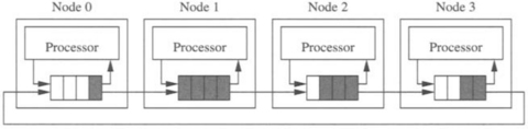
The basic idea for the unidirectional ring is the following: In a deadlocked configuration no packet is able to advance. Thus, if there is at least one empty packet buffer in the ring, there is no deadlock. A packet from the previous node is able to advance, and sooner or later, all the packets will advance. To keep at least one empty packet buffer in the ring, a node is not allowed to inject a new packet if it fills the local queue. Two or more empty buffers in the local queue are required to inject a new packet. Note that each node only uses local information. Figure 3.12 shows a unidirectional ring with four nodes. Node 1 cannot inject packets because its local queue is full. Note that this queue was not filled by node 1, but by transmission from node 0. Node 2 cannot inject packets because it would fill its local queue. In this case, injecting a packet at node 2 would not produce deadlock, but each node only knows its own state. Nodes 0 and 3 are allowed to inject packets.
This mechanism can be easily extended for tori with central queues and dimension-order routing. Assuming bidirectional channels, every dimension requires two queues, one for each direction. A given queue can receive packets from the local node and from lower dimensions. As above, a node is not allowed to inject a new packet if it fills the corresponding queue. Additionally, a packet cannot move to the next dimension if it fills the queue corresponding to that dimension (in the appropriate direction). When two or more empty buffers are available in some queue, preference is given to packets changing dimension over newly injected packets. This mechanism can also be extended to other topologies like meshes.
Although this deadlock avoidance mechanism is very simple, it cannot be used for wormhole switching. Also, modifying it so that it supports adaptive routing is not trivial.
3.4 Deadlock Avoidance in Switch-Based Networks
Deadlocks arise because network resources (buffers or channels) are limited. If we compare a router in a direct network with a switch in a switch-based network (either a buffered multistage network or a switch-based network with regular or irregular topology), they are very similar. Regarding deadlocks, the only difference is that a router has a single processor attached to it while a switch may be connected to zero, one, or more processors. So, we can focus on the topology connecting the switches and model a switch-based network by means of a direct network. Switches that are not connected to any processor can neither send nor receive packets. Switches connected to one or more processors are allowed to send and receive packets. With this simple model, the theoretical results for deadlock avoidance in direct networks can also be applied to switch-based networks.
There is a special case that is worth mentioning because it includes most MINs. The behavior of these networks regarding deadlocks is different depending on whether recirculation is allowed. If it is allowed, a packet may cross the network several times, reaching an intermediate node after each circulation but the last one. Assuming that the packet is not ejected from the network at intermediate nodes, the behavior of MINs regarding deadlocks is similar to that of direct networks. As mentioned above, the theoretical results for the latter are valid for the former.
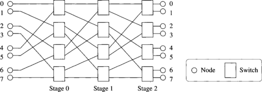
However, if recirculation is not allowed, there exists a natural ordering in the way resources are reserved, thus avoiding deadlock. Usually, recirculation is not allowed. Consider the unidirectional MIN in Figure 3.13. Packets are only routed from left to right. The critical resources regarding deadlock are the channels connecting stages or the buffers associated with them. Packets are first routed at a switch from the first stage. Then they are routed at the second stage, and so on, until they reach their destination. As there is no recirculation, once a packet has reserved an output channel from the first stage it will not request another output channel from the first stage. Thus, there is no dependency between channels from the same stage. Similarly, a packet that has reserved an output channel from a given stage will not request another output channel from a previous stage. There are only dependencies from channels in a given stage to channels in the next stages. As a consequence, there is not any cyclic dependency between channels, thus avoiding deadlocks.
Using the concept of channel class defined in Section 3.2.1, we can define as many classes as stages because there is no dependency between channels from the same stage. Dependencies between classes also form an acyclic graph because there is not any dependency from the class corresponding to a given stage to the classes corresponding to previous stages.
For bidirectional MINs the situation is very similar. Bidirectional channels can be considered as two unidirectional channels. Although some stages are crossed twice by each packet (in the forward and backward directions), different channels are used for each direction. Thus, there is also a natural ordering of stages.
3.5 Deadlock Prevention in Circuit Switching and PCS
Deadlock prevention techniques request resources in such a way that no deadlock can arise. The simplest deadlock prevention technique consists of reserving all the resources before they are used. This is the way circuit switching and PCS work [124, 126]. In these switching techniques, the source node sends a probe that sets up the whole path. Once the path has been established, data flits are forwarded into the network. No deadlock can arise because all the resources have been reserved before starting packet transmission. If the probe cannot advance, it is allowed to backtrack, releasing some previously reserved resources. If the probe is not able to establish any path (usually due to the existence of faulty channels or nodes), it returns to the source node, releasing all the network resources.
It should be noted that if backtracking is not allowed, then the probe may block during path setup, keeping all the channels it previously reserved. In this case, the behavior of circuit switching and PCS regarding deadlocks is identical to that of wormhole switching, and deadlock prevention techniques cannot be used.
3.6 Deadlock Recovery
Deadlock recovery techniques do not impose any restriction on routing functions, thereby allowing deadlocks to form. These techniques require a mechanism to detect and resolve potential deadlock situations. When a deadlock is detected, one or more packets are obliged to release the buffer resources they are keeping, allowing other packets to use them and breaking the deadlock.
Deadlock recovery techniques are useful only if deadlocks are rare. Otherwise the overhead produced by deadlock detection and buffer releasing would degrade performance considerably. Also, deadlock recovery mechanisms should be able to recover from deadlocks faster than they occur.5 Therefore, it is important for us to know how probable deadlocks might be for certain network configurations and to understand the parameters that most influence deadlock formation. For example, wormhole switching is more prone to deadlock than are other switching techniques [347]. This is because each packet may hold several channel resources spanning multiple nodes in the network while being blocked. We therefore concentrate on wormhole-switched recovery schemes.
3.6.1 Deadlock Probability
Recent work by Pinkston and Warnakulasuriya on characterizing deadlocks in interconnection networks has shown that a number of interrelated factors influence the probability of deadlock formation [283, 347]. Among the more influential of these factors is the routing freedom, the number of blocked packets, and the number of resource dependency cycles. Routing freedom corresponds to the number of routing options available to a packet being routed at a given node within the network and can be increased by adding physical channels, adding virtual channels, and/or increasing the adaptivity of the routing algorithm. It has been quantitatively shown that as the number of network resources (physical and virtual channels) and the routing options allowed on them by the routing function increase (routing freedom), the number of packets that tend to block significantly decreases, the number of resource dependency cycles decreases, and the resulting probability of deadlock also decreases exponentially. This is due to the fact that deadlocks require highly correlated patterns of cycles, the complexity of which increases with routing freedom. A conclusion of Pinkston and Warnakulasuriya’s work is that deadlocks in interconnection networks can be highly improbable when sufficient routing freedom is provided by the network and fully exploited by the routing function. In fact, it has been shown that as few as two virtual channels per physical channel are sufficient to virtually eliminate all deadlocks up to and beyond saturation in 2-D toroidal networks when using unrestricted fully adaptive routing [283, 347]. This verifies previous empirical results that estimated that deadlocks are infrequent [9, 179]. However, the frequency of deadlock increases considerably when no virtual channels are used.
The network state reflecting resource allocations and requests existing at a particular point in time can be depicted by the channel wait-for graph (CWG). The nodes of this graph are the virtual channels reserved and/or requested by some packet(s). The solid arcs point to the next virtual channel reserved by the corresponding packet. The dashed arcs in the CWG point to the alternative virtual channels a blocked packet may acquire in order to continue routing. The highly correlated resource dependency pattern required to form a deadlocked configuration can be analyzed with the help of the CWG. A knot is a set of nodes in the graph such that from each node in the knot it is possible to reach every other node in the knot. The existence of a knot is a necessary and sufficient condition for deadlock [283]. Note that checking the existence of knots requires global information and cannot be efficiently done at run time.
Deadlocks can be characterized by deadlock set, resource set, and knot cycle density attributes. The deadlock set is the set of packets that own the virtual channels involved in the knot. The resource set is the set of all virtual channels owned by members of the deadlock set. The knot cycle density represents the number of unique cycles within the knot. The knot cycle density indicates complexity in correlated resource dependency required for deadlock. Deadlocks with smaller knot cycle densities are likely to affect local regions of the network only, whereas those having larger knot cycle densities are likely to affect more global regions of the network and will therefore be more harmful.
Figure 3.14 shows eight packets (m1, m2, m3, m4, m5, m6, m7, and m8) being routed minimal-adaptively in a network with two virtual channels per physical channel. The source and destination nodes of packet mi, are labeled si and di, respectively. Packet m1 has acquired channels vc0 and vc1, and requires either vc3 or vc11 to continue. Similarly, all other packets have also acquired two virtual channels each and are waiting to acquire one of two possible alternative channels in order to proceed. All of the packets depicted here are waiting for resources held by other packets in the group and therefore will be blocked indefinitely, thus constituting a deadlock.
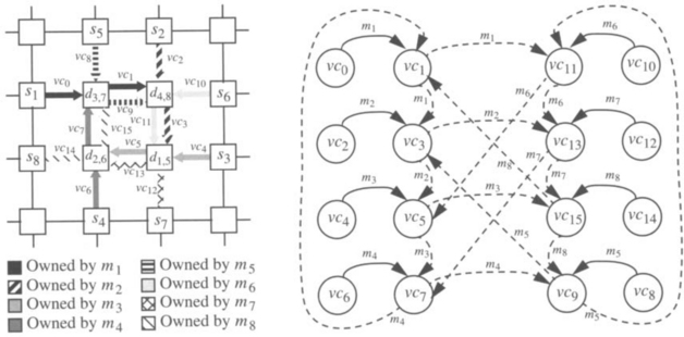
Figure 3.14 A multicycle deadlock formed under minimal adaptive routing with two virtual channels per physical channel. (from [283])
The CWG for the packets in this example is also depicted in Figure 3.14. The deadlock set is the set {m0 … m7}. The resource set is {vc0 … vc15}. The knot cycle density is 24.
A cyclic nondeadlocked configuration in which multiple cycles exist but do not form a deadlock is depicted in Figure 3.15. The dependencies are similar to those in Example 3.10 except that the destination of packet m4 is changed, giving it an additional channel alternative to use to continue routing. While the same resource dependency cycles as in the previous example still exist, this scenario does not constitute a deadlock since packet m4 may eventually acquire vc16 to reach its destination and subsequently release vc7, which will allow one of the two packets waiting for this channel (m3 or m7) to continue. Other packets will then be able to follow in a like manner. Hence, this small increase in routing freedom is sufficient enough to complicate the correlated resource dependencies required for deadlock. It can be observed in the CWG in Figure 3.15 that virtual channels do not form any knot because it is not possible to reach any other node from vc16.
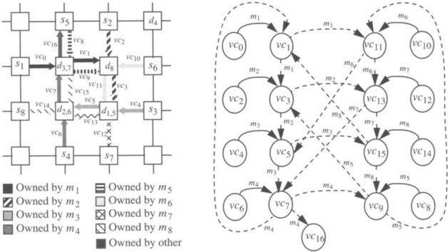
Figure 3.15 A cyclic nondeadlocked network state under minimal adaptive routing with two virtual channels per physical channel. (from [283])
The deadlock in Example 3.10 formed because all of the packets involved had exhausted much of their routing freedom. Increasing routing freedom makes deadlocks highly improbable even beyond network saturation. However, increased routing freedom does not completely eliminate the formation of cyclic nondeadlocks resulting from correlated packet blocking behavior, as illustrated in Example 3.11. Even though they do not lead to deadlock formation, cyclic nondeadlocks can lead to situations where packets block cyclically faster than they can be drained and, therefore, remain blocked for extended periods, causing increased latency and reduced throughput. It has been shown in [283] that networks that maximize routing freedom have the benefit of reducing the probability of cyclic nondeadlocks over those that do not. In general, given sufficient routing freedom provided by the network, deadlock-recovery-based routing algorithms designed primarily to maximize routing freedom have a potential performance advantage over deadlock-avoidance-based routing algorithms designed primarily to avoid deadlock (and secondarily to maximize routing freedom). This is what makes deadlock-recovery-based routing interesting. In Chapter 9, we will confirm this intuitive view.
In addition to increasing routing freedom, another method for reducing the probability of deadlock (and cyclic nondeadlock) is to limit packet injection, thereby limiting the number of packets that enter and block within the network at saturation. One approach is to limit the number of injection ports to one. Other mechanisms can be used to further limit injection. For example, a simple mechanism that uses only local information allows the injection of a new packet if the total number of free output virtual channels in the node is higher than a given threshold. This mechanism was initially proposed to avoid performance degradation in networks using deadlock avoidance techniques [220]. It is also well suited for minimizing the likelihood of deadlock formation in deadlock recovery [226].
3.6.2 Detection of Potential Deadlocks
Deadlock recovery techniques differ in the way deadlocks are detected and in the way packets are obliged to release resources. A deadlocked configuration often involves several packets. Completely accurate deadlock detection mechanisms are not feasible because they require exchanging information between nodes (centralized detection). This is not always possible because channels may be occupied by deadlocked packets. Thus, less accurate heuristic mechanisms that use only local information (distributed detection) are preferred. For instance, if a header flit is blocked for longer than a certain amount of time, it can be assumed that the corresponding packet is potentially deadlocked.
Deadlock detection mechanisms using a timeout heuristic can be implemented either at the source node or at intermediate nodes that contain a packet header. If deadlocks are detected at the source node, a packet can be considered deadlocked when the time since it was injected is longer than a threshold [289] or when the time since the last flit was injected is longer than a threshold [179]. In either case, a packet cannot be purged from the source node until the header reaches the destination. This can be achieved without end-to-end acknowledgments by padding packets with additional dummy flits as necessary to equal the maximum distance allowed by the routing algorithm for the source-to-destination pair [179]. Detection at the source node requires that each injection port have an associated counter and comparator. On the other hand, if deadlocks are detected at intermediate nodes, each virtual channel requires an associated counter and comparator to measure the time headers block [8].
Heuristic deadlock detection mechanisms may not detect deadlocks immediately. Also, they may indicate that a packet is deadlocked when it is simply waiting for a channel occupied by a long packet (i.e., false deadlock detection). Moreover, when several packets form a deadlocked configuration, it is sufficient to release the buffer occupied by only one of the packets to break the deadlock. However, because heuristic detection mechanisms operate locally and in parallel, several nodes may detect deadlock concurrently and release several buffers in the same deadlocked configuration. In the worst case, it may happen that all the packets involved in a deadlock release the buffers they occupy. These overheads suggest that deadlock-recovery-based routing can benefit from highly selective deadlock detection mechanisms. For instance, turn selection criteria could also be enforced to limit a packet’s eligibility to use recovery resources [279].
The most important limitation of heuristic deadlock detection mechanisms arises when packets have different lengths. The optimal value of the timeout for deadlock detection heavily depends on packet length unless some type of physical channel monitoring of neighboring nodes is implemented. When a packet is blocked waiting for channels occupied by long packets, the selected value for the timeout should be high in order to minimize false deadlock detection. As a consequence, deadlocked packets have to wait for a long time until deadlock is detected. In these situations, latency becomes much less predictable. The poor behavior of current deadlock detection mechanisms considerably limits the practical applicability of deadlock recovery techniques. Some current research efforts aim at improving deadlock detection techniques [226].
3.6.3 Progressive and Regressive Recovery Techniques
Once deadlocks are detected and packets made eligible to recover, there are several alternative actions that can be taken to release the buffer resources occupied by deadlocked packets. Deadlock recovery techniques can be classified as progressive or regressive. Progressive techniques deallocate resources from other (normal) packets and reassign them to deadlocked packets for quick delivery. Regressive techniques deallocate resources from deadlocked packets, usually killing them (abort-and-retry). The set of possible actions taken depends on where deadlocks are detected.
If deadlocks are detected at the source node, regressive deadlock recovery is usually used. A packet can be killed by sending a control signal that releases buffers and propagates along the path reserved by the header. This is the solution proposed in compressionless routing [179]. After a random delay, the packet is injected again into the network. This reinjection requires a packet buffer associated with each injection port. Note that a packet that is not really deadlocked may resume advancement and even start delivering flits at the destination after the source node presumes it is deadlocked. Thus, this situation also requires a packet buffer associated with each delivery port to store fragments of packets that should be killed if a kill signal reaches the destination node. If the entire packet is consumed without receiving a kill signal, it is delivered. Obviously, this use of packet buffers associated with ports restricts packet size.
If deadlocks are detected at an intermediate node containing the header, then both regressive and progressive deadlock recovery are possible. In regressive recovery, a deadlocked packet can be killed by propagating a backward control signal that releases buffers from the node containing the header back to the source by following the path reserved by the packet in the opposite direction. Instead of killing a deadlocked packet, progressive recovery allows resources to be temporarily deallocated from normal packets and assigned to a deadlocked packet so that it can reach its destination. Once the deadlocked packet is delivered, resources are reallocated to the preempted packets. This progressive deadlock recovery technique was first proposed in [8, 9]. This technique is clearly more efficient than regressive deadlock recovery. Hence, we will study it in more detail.
Figure 3.16 shows the router organization for the first progressive recovery technique proposed, referred to as Disha [8, 9, 10]. It is identical to the router model proposed in Section 2.1 except that each router is equipped with an additional central buffer, or deadlock buffer. This resource can be accessed from all neighboring nodes by asserting a control signal (arbitration for it will be discussed below) and is used only in the case of suspected deadlock. Systemwide, these buffers form what is collectively a deadlock-free recovery lane that can be visualized as a floating virtual channel shared by all physical dimensions of a router. On the event of a suspected deadlock, a packet is switched to the deadlock-free lane and routed adaptively along a path leading to its destination, where it is consumed to avert the deadlock. Physical bandwidth is deallocated from normal packets and assigned to the packet being routed over the deadlock-free lane to allow swift recovery. The aforementioned control signal is asserted every time a deadlocked packet flit uses physical channel bandwidth so that the flit is assigned to the deadlock buffer at the next router. The mechanism that makes the recovery lane deadlock-free is specific to how recovery resources are allocated to suspected deadlocked packets.
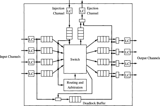
Implementations can be based on restricted access (Disha sequential [8]) or structured access (Disha concurrent [10]) to the deadlock buffers as discussed below.
To gain an intuitive understanding of how deadlock can be progressively recovered from, consider the deadlocked configuration depicted in Figure 3.17 for a k-ary 2-cube network. For simplicity, we illustrate the operation with two virtual channels per physical channel. In this configuration, packets P2 and P3 reserved the virtual channels connecting routers Ra and Rb, and are blocked at router Rb waiting for any of the virtual channels occupied by P4 and P5 (and, likewise, P4 and P5 are waiting for any of the virtual channels occupied by P6 and P7, and so on). There may be other cycles in the network. Assume that k cycles exist (one is shown in the figure). We show the formation of Disha recovery paths through routers Ra, Rb, and Rc in Figures 3.18 and 3.19 for this deadlock scenario.
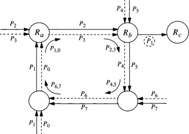
Figure 3.17 Deadlocked configuration for Example 3.12.
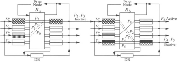
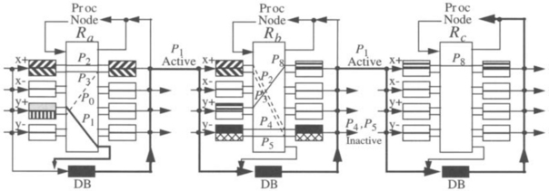
In the absence of deadlocks, the router switch is configured as specified by the normal decision and arbitration logic. However, once a potential deadlock situation is detected by router Ra, its crossbar is configured to redirect the deadlocked packet to its deadlock buffer for handling by the deadlock routing logic. Figure 3.18 shows the state of routers Ra and Rb when packet P1 (which is being minimally routed in the final dimension toward its destination) is blocked by packets P2 and P3.
Unable to route P1’s header for the specified timeout threshold, router Ra suspects the packet is involved in a deadlock and checks its eligibility to recover. Router Ra then routes the header of the eligible packet through its crossbar, into its central deadlock buffer (bypassing normal edge output buffers currently occupied by blocked packets P2 and P3), and preempts the idle output physical channel from P2 and P3, which were already inactive due to deadlock blockage further downstream (see Figure 3.19). The corresponding control line is asserted for the channel, indicating to router Rb to route the incoming header of P1 through the recovery lane (deadlock buffer) instead of the normal virtual channel lane (edge input buffer) currently occupied by P2 and P3.
In like manner at subsequent routers, packet P1 is routed entirely on deadlock buffer resources until it reaches its destination (Rc), bypassing completely the normal routing section of each router for speedy recovery. These actions are shown in Figure 3.19. This eliminates one cycle, reducing the number of cycles to k − 1. By induction, it follows that the network safely recovers from all deadlocks. Note that allowing any one of the packets to progressively recover breaks one cycle in the deadlocked configuration. Also, there is no ordering as to which packet should be placed on the deadlock-free recovery lane.
It could happen that a recovering packet in the deadlock buffer requires the same output physical channel at a router as normal unblocked (active) packets currently being routed using edge buffer resources. This case, which is illustrated in Figure 3.19 at router Rb, poses no problem. Here, packet P8 may be active. However, P1 takes precedence and preempts the physical channel bandwidth, suspending normal packet transmission until deadlock has cleared. Although this might lead to additional discontinuities in flit reception beyond that suffered from normal virtual channel multiplexing onto physical channels, all flits of packet P8 are guaranteed to reach their destination safely. Given that suspected deadlock occurrences are infrequent anyway, the occasional commandeering of output channels should not significantly degrade performance. However, router organizations that place the deadlock buffer on the input side of the crossbar would require crossbar reconfiguration and logic to remember the state of the crossbar before it was reconfigured so that the suspended input buffer can be reconnected to the preempted output buffer once deadlock has cleared [9]. This situation can be avoided simply by connecting the deadlock buffer to the output side of the crossbar as shown in Figure 3.16. This positioning of the deadlock buffer also makes recovering from self-deadlocking situations less complicated (i.e., those situations arising from nonminimal routing where packets are allowed to visit the same node twice).
Although deadlock buffers are dedicated resources, no dedicated channels are required to handle deadlocked packets. Instead, network bandwidth is allocated for deadlock freedom only in the rare instances when probable deadlocks are detected; otherwise, all network bandwidth is devoted to fully adaptive routing of normal packets. Thus, most of the time, all edge virtual channels are used for fully adaptive routing to optimize performance. This is as opposed to deadlock avoidance routing schemes that constantly devote some number of edge virtual channels for avoiding improbable deadlock situations. The number of deadlock buffers per node should be kept minimal. Otherwise, crossbar size would increase, requiring more gates and resulting in increased propagation delay. This is the reason why central buffers are used in Disha. Some alternative approaches use edge buffers instead of central buffers, therefore providing a higher bandwidth to drain blocked packets [94, 274]. However, in these cases more buffers are required, increasing crossbar size and propagation delay.
Deadlock freedom on the deadlock buffers is essential to recovery. This can be achieved by restricting access with a circulating token that enforces mutual exclusion on the deadlock buffers. In this scheme, referred to as Disha sequential [8], only one packet at a time is allowed to use the deadlock buffers. An asynchronous token scheme was proposed in [8] and implemented in [282] to drastically reduce propagation time and hide token capture latency. The major drawback of this scheme, however, is the token logic, which presents a single point of failure. Another potential drawback is the fact that recovery from deadlocks is sequential. This could affect performance if deadlocks become frequent or get clustered in time. Simultaneous deadlock recovery avoids these drawbacks, which will be discussed shortly.
An attractive and unique feature of Disha recovery is that it reassigns resources to deadlocked packets instead of killing packets and releasing the resources occupied by them. Based on the extension of Theorem 3.1 as mentioned in Section 3.2.3, Disha ensures deadlock freedom by the existence of a routing subfunction that is connected and has no cyclic dependencies between resources. Disha’s routing subfunction is usually defined by the deadlock buffers, but, for concurrent recovery discussed below, it may also make use of some edge virtual channels. An approach similar to Disha was proposed in [88, 94, 274], where the channels supplied by the routing subfunction can only be selected if packets are waiting for longer than a threshold. The circuit required to measure packet waiting time is identical to the circuit for deadlock detection in Disha. However, the routing algorithms proposed in [88, 94, 274] use dedicated virtual channels to route packets waiting for longer than a threshold.
Disha can also be designed so that several deadlocks can be recovered from concurrently (Disha Concurrent [10]). In this case, the token logic is no longer necessary. Instead, an arbiter is required in each node so that simultaneous requests for the use of the deadlock buffer coming from different input channels are handled [281]. For concurrent recovery, more than one deadlock buffer may be required at each node for some network topologies, but even this is still the minimum required by progressive recovery. Exercise 3.6 shows how simultaneous deadlock recovery can be achieved on meshes by using a single deadlock buffer and some edge buffers.
In general, simultaneous deadlock recovery can be achieved on any topology with Hamiltonian paths by using two deadlock buffers per node. Nodes are labeled according to their position in the Hamiltonian path. One set of deadlock buffers is used by deadlocked packets whose destination node has a higher label than the current node. The second set of deadlock buffers is used by deadlocked packets whose destination node has a lower label than the current node. All edge virtual channels can be used for fully adaptive routing. As deadlock buffers form a connected routing subfunction without cyclic dependencies between them, all deadlocked packets are guaranteed to be delivered by using deadlock buffers. Similarly, simultaneous deadlock recovery can be achieved on any topology with an embedded spanning tree by using two deadlock buffers per node.
3.7 Livelock Avoidance
The simplest way to avoid livelock is by limiting misrouting. Minimal routing algorithms are a special case of limited misrouting in which no misrouting is allowed. The number of channels reserved by a packet is upper bounded by the network diameter. If there is no deadlock, the packet is guaranteed to be delivered in the absence of faults. Minimal routing algorithms usually achieve a higher performance when wormhole switching is used because packets do not consume more channel bandwidth than the minimum amount required.
An important reason to use misrouting is routing around faulty components. If only minimal paths are allowed, and the link connecting the current and destination nodes is faulty, the packet is not able to advance. Given a maximum number of faults that do not disconnect the network, it has been shown that limited misrouting is enough to reach all the destinations [126]. By limiting misrouting, there is also an upper bound for the number of channels reserved by a packet, thus avoiding livelock. Misrouting can be limited either by designing an appropriate routing algorithm or by adding a field to the packet header to keep the misrouting count.
As far as we know, the only case in which misrouting cannot be limited without inducing deadlock is deflection routing. As indicated in Section 3.3.2, this routing technique avoids deadlock by using any free channel to forward packets. Limiting misrouting may produce deadlock if the only available channel at a given node cannot be used because misrouting is limited.
It has been shown that deflection routing is livelock-free in a probabilistic way [189]. Assuming that channels belonging to minimal paths are given preference over those belonging to nonminimal paths, the probability of finding all the minimal paths busy decreases as the number of tries increases. Thus, when a sufficiently long period of time is considered, the probability of not reaching the destination approaches zero for all the packets. In other words, packets will reach their destination sooner or later. In practice, it has been shown that very few misrouting operations are required on average when deflection routing is used.
3.8 Engineering Issues
This chapter is mostly theoretical. However, the ideas presented in this chapter have a direct application to the design of routing algorithms. Thus, the impact on performance is directly related to the impact of routing algorithms on performance. Wormhole routers could not be used in multiprocessors and multicomputers if deadlock handling were not considered in the router design. Moreover, multicast and fault-tolerant routing algorithms also require handling deadlock and livelock. The techniques presented in Chapters 5 and 6 will build upon the techniques presented in this chapter.
As indicated in Chapter 2, the design of hardware routers using wormhole switching increased performance by several orders of magnitude. But designers of wormhole routers had to consider deadlock avoidance seriously. SAF switching provided enough buffering space so that deadlock avoidance was not a serious problem, even if the routing algorithm was not deadlock-free. The probability of deadlock was almost negligible. Additionally, routing algorithms were implemented in software, considerably easing the task of recovering from deadlocks. When wormhole switching was proposed, deadlock avoidance techniques were immediately considered. The probability of deadlock in wormhole networks is high enough to block the whole network in a few seconds if the routing algorithm is not deadlock-free.
The first theory of deadlock avoidance for wormhole switching followed the ideas previously proposed for operating systems: deadlocks are avoided by avoiding cyclic dependencies between resources. Despite its simplicity it had a tremendous impact. It allowed the design of the routers used in almost all current multicomputers.
Adaptive routing algorithms may improve performance considerably over deterministic routing algorithms, especially when traffic is not uniform. However, adaptive routers are more complex, slowing down clock frequency. Thus, there is a trade-off. Designing fully adaptive routing algorithms under the constraint of eliminating cyclic dependencies between resources produces a considerable increase in the complexity of the router.
Except for 2-D networks, fully adaptive routers were not feasible until the proposal of more relaxed conditions for deadlock avoidance (similar to Theorem 3.1). Relaxed conditions allowed minimal fully adaptive routing by adding only one virtual channel per physical channel. Thus, relaxed conditions like the one proposed by Theorem 3.1 are the key for the design of adaptive routers. But even by using those relaxed conditions, adaptive routing algorithms require more resources than deterministic ones. In addition to increasing the number of virtual channels, crossbars become more complex. Also, adaptive routing has to select one routing option, considering channel status. As a consequence, deterministic routers are faster than adaptive routers. But the benefits from using fully adaptive routing may well outweigh the slower clock frequency (see Chapter 9).
Most researchers think that adaptive routing algorithms will be used for future router designs. We agree with this view. Chips are becoming faster, but transmission delay across wires remains the same. When routers become so fast that flit transmission across physical channels becomes the slowest stage in the pipeline, adaptive routers will definitely outperform deterministic routers under all traffic conditions.
Meanwhile, in an attempt to eliminate the need for excessive hardware resources and use existing resources more efficiently, some researchers proposed the use of deadlock recovery techniques. Deadlocks are frequent when the network reaches the saturation point if the number of dimensions is small and no virtual channels are used. Because deadlocks in wormhole switching were believed to be frequent regardless of design parameters, deadlock recovery techniques were not rigorously pursued until recently. New empirical studies have shown that deadlocks are generally very infrequent in the presence of sufficient routing freedom, making deadlock recovery an attractive alternative. However, deadlock recovery has some overhead associated with it, particularly if deadlocked packets are killed and injected again into the network as with regressive recovery. Progressive recovery techniques such as Disha minimize overheads as they reassign channel bandwidth so that deadlocked packets are quickly delivered and removed from the network.
Moreover, as Disha does not require dedicated channels for deadlock avoidance, the overhead in the absence of deadlock is small. The advantages of Disha are especially noticeable in tori. At least three virtual channels per physical channel are required for fully adaptive routing using the condition proposed by Theorem 3.1, and only one of them is used for fully adaptive routing. Disha requires only a single virtual channel for fully adaptive routing plus one central buffer (or two, depending on whether sequential or concurrent deadlock recovery is implemented). Therefore, additional virtual channels in Disha serve to increase throughput as all can be used for fully adaptive routing.
However, Disha has some potential drawbacks. The circuit implementing the circulating token is a single point of failure. This drawback can be easily eliminated by using concurrent deadlock recovery, but this may require an additional central buffer. Also, deadlock detection circuitry is required, such as a counter and comparator for each virtual input channel. But perhaps the most important drawback arises when some or all packets are long. The small bandwidth offered by a single central buffer is usually enough to deliver short deadlocked packets. However, when long packets become deadlocked, recovering from deadlock may take a while. As a consequence, other deadlocked packets have to wait a considerable amount of time before the central buffer becomes available, increasing latency and reducing throughput. In these situations, latency becomes much less predictable. Additionally, the optimal value of the timeout threshold for deadlock detection heavily depends on packet length unless some type of physical channel monitoring of neighboring nodes is implemented. Therefore, short messages or messages split into fixed-length shorter packets may be preferred. In this case, the increased performance achieved by Disha should be weighed against the overheads associated with packetizing messages.
It is important to note that performance may degrade considerably before reaching a deadlocked configuration. Even if deadlock does not occur, performance may degrade severely when the network reaches the saturation point. This behavior typically arises when cyclic dependencies between channels are allowed. In this case, regardless of whether deadlock avoidance or progressive recovery is used, the bandwidth provided by the resources to escape from deadlock should be high enough to drain packets from cyclic waiting chains as fast as they are formed. For some traffic patterns, providing that bandwidth would require too many resources. Alternatively, packet injection can be limited so that the network cannot reach the saturation point (see Section 9.9). Injection limitation techniques not only eliminate performance degradation beyond the saturation point but also reduce the frequency of deadlock to negligible values.
Finally, as the number of transistors per chip increases, VCT switching becomes more feasible. Although the probability of deadlocks is less than in wormhole switching, VCT switching must still guard against deadlocks. Simple techniques such as deflection routing have proven to be very effective. Nevertheless, the main drawback of VCT is that it requires buffers deep enough to store one or more packets. If these buffers are implemented in hardware, messages must be split into relatively short packets, thus increasing latency. Like Disha, VCT switching is more suitable when messages are short or packetized, as in distributed shared-memory multiprocessors with hardware cache coherence protocols.
3.9 Commented References
The alternative approaches to handle deadlocks were described in [321]. This paper mainly focuses on distributed systems. Thus, the conclusions are not directly applicable to interconnection networks. The theoretical background for deadlock avoidance in packet-switched networks (SAF) can be found in [133, 140, 237]. These results were developed for data communication networks.
Some tricks were developed to avoid deadlock in SAF and VCT switching, like restricting packet injection [166, 298]. The most popular trick is deflection routing [137], also known as “hot potato” routing.
Wormhole switching achieves a higher performance than SAF switching, but it is also more deadlock-prone. A necessary and sufficient condition for deadlock-free routing was proposed in [77]. Although this condition was only proposed for deterministic routing functions, it has been extensively applied to adaptive routing functions. In this case, that condition becomes a sufficient one. An innovative view of the condition for deadlock-free adaptive routing is the turn model [129]. This model analyzes how cyclic dependencies are formed, prohibiting enough turns to break all the cycles. The turn model is based on the theory proposed in [77]. It will be studied in detail in Chapter 4.
With the exception of the tricks, all of the above-mentioned results avoid deadlock by preventing the existence of cyclic dependencies between storage resources. Fully adaptive routing requires a considerable amount of resources if cyclic dependencies are avoided. More flexibility can be achieved by relaxing the condition for deadlock-free routing. Sufficient conditions for deadlock-free adaptive routing in SAF networks were proposed in [86, 277, 278]. A necessary condition was proposed in [63]. The combination of those conditions does not produce a necessary and sufficient condition.
Developing relaxed conditions for wormhole switching is more difficult because packets can hold several channels simultaneously. Sufficient conditions for deadlock-free adaptive routing were independently proposed by several authors [24, 86, 91, 136, 207, 331].
The above-mentioned conditions can be relaxed even more. A necessary and sufficient condition for deadlock-free routing in wormhole switching was proposed in [92, 97]. The necessary condition is only valid for coherent routing functions defined on N × N. This condition can be easily modified for SAF and VCT switching, as shown in [98], where the restriction about coherency is removed. The restrictions about coherency and the domain of the routing function are removed in [110, 307, 309] for wormhole switching. However, these results supply temporal (dynamic) conditions rather than structural (static) ones. Another necessary and sufficient condition for deadlock-free routing is proposed in [209], extending the sufficient condition presented in [207].
An intermediate approach between deadlock avoidance and recovery was proposed in [88, 94] and, more recently, in [274], which uses a time-dependent selection function. The use of deadlock recovery techniques for wormhole switching was first proposed in [289] and later in [179]. The recovery techniques proposed were based on regressive abort-and-retry, thus incurring large overheads and increased packet latency. More recently, Disha was proposed in [8, 9]; it is a more efficient progressive deadlock recovery technique. From a logical point of view, it is similar to the time-dependent selection function proposed in [88, 94]. However, the implementation of Disha is more efficient. Deadlock freedom is based on an extension of the conditions proposed in [86, 92]. That extension was proposed in [10].
The frequency of deadlocks was first approximated in [9, 179] and found to be rare. More recent empirical studies by [283, 347] confirm that deadlocks are highly improbable in networks with few virtual channels, small node degree, and relaxed routing restrictions, thus making deadlock recovery routing tenable.
Deadlock prevention in pipelined circuit switching was analyzed in [124, 126]. The corresponding analysis for scouting and configurable flow control techniques was presented in [79, 99]. These techniques will be studied in Chapter 6.
Finally, probabilistic livelock avoidance was analyzed in [189].
Exercises
3.1. Consider a 2-D mesh using VCT switching. The routing function R1 uses dimension-order routing (XY routing). This routing function forwards a packet across horizontal channels until it reaches the column where its destination node is. Then the packet is forwarded through vertical channels until it reaches its destination. Draw the channel dependency graph for R1 on a 3 × 3 mesh. Now consider a minimal fully adaptive routing function R. It forwards packets following any minimal path without adding virtual channels. Draw the extended channel dependency graph for R1 on a 3 × 3 mesh, considering R1 as a subfunction of R.
Solution It is well known that R1 is connected and deadlock-free. Figure 3.20 shows the channel dependency graph for R1 on a 3 × 3 mesh. Black circles represent the unidirectional channels supplied by R1 and are labeled as cij, where i and j are the source and destination nodes of the channel, respectively. As a reference, channels are also represented by thin lines. Arcs represent channel dependencies. The graph has no cycles.
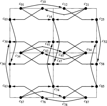
Figure 3.21 shows the extended channel dependency graph for R1 on a 3 × 3 mesh when it is considered as a routing subfunction of R. Solid arcs represent direct dependencies. Obviously these dependencies are the same as in Figure 3.20.
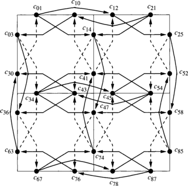
Dashed arcs represent direct cross-dependencies. It can be seen that there are direct cross-dependencies from Y channels toward X channels that produce cycles. Effectively, a packet traveling southeast may use a Y channel (supplied by R but not by R1), then request an X channel (supplied by R1). The same Y channel may be requested as an escape channel by a packet traveling south (supplied by R1). If direct cross-dependencies were not considered, we would erroneously conclude that R is deadlock-free. Figure 3.2 shows a deadlocked configuration for R.
3.2. Consider a 2-D mesh using wormhole switching. Each physical channel consists of a single virtual channel in each direction, except north channels that are split into two virtual channels. Channels corresponding to north, east, south, and west directions are denoted as N1, N2, E, S, and W. The routing function R allows the use of every minimal path using N2, E, S, and W channels. N1 channels can only be used when the destination node is located north from the current node. Draw a deadlocked configuration for R on a 3 × 3 mesh. If R1 is defined by the set of channels N1, E, S, and W, using expression (3.2), draw the extended channel dependency graph for R1.
Solution As shown in Example 3.5, R is deadlock-free for VCT and SAF switching. However, R is not deadlock-free when wormhole switching is used. Figure 3.22 shows a deadlocked configuration on a 3 × 3 mesh. Solid lines represent the channel(s) already reserved by each packet. Dashed lines represent the next channel requested by each packet. Arrows point at the destination node for the packet. In this configuration, a single routing option is available to each packet. As can be seen, no packet is able to advance. One of the packets has reserved one E channel and two N2 channels, then requested another E channel. Thus, such a deadlocked configuration is only valid for wormhole switching.
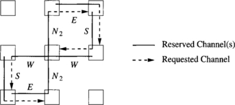
Figure 3.23 shows the extended channel dependency graph for R1 on a 3 × 3 mesh. Solid arcs represent direct dependencies. Dashed arcs represent indirect dependencies. As the routing subfunction is defined by a channel subset, there is not any cross-dependency. As can be seen, there are cycles in the graph. For instance, channels c12, c25, c54, c43, c36, and c67 form a cycle. This cycle corresponds to the deadlocked configuration presented in Figure 3.22.
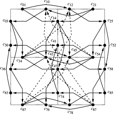
3.3. Consider a 2-D mesh using wormhole switching such that each physical channel is split into two virtual channels. Virtual channels are grouped into two sets or virtual networks. The first virtual network consists of one virtual channel in each direction. It is used to send packets toward the east (X-positive). It will be referred to as the eastward virtual network. The second virtual network also consists of one virtual channel in each direction. It is used to send packets toward the west (X-negative) and will be referred to as the westward virtual network. When the X coordinates of the source and destination nodes are equal, packets can be introduced in either virtual network. Figure 3.24 shows the virtual networks for a 4 × 4 mesh. The routing algorithms for the eastward and westward virtual networks are based on west-last and east-last, respectively [129]. Once a packet has used a west (east) channel in the eastward (westward) virtual network, it cannot turn again. However, 180-degree turns are allowed in Y channels except in the east (west) edge of the mesh. Assuming that a node cannot forward a packet destined for itself through the network, show that the routing function is not coherent, and prove that it is deadlock-free.
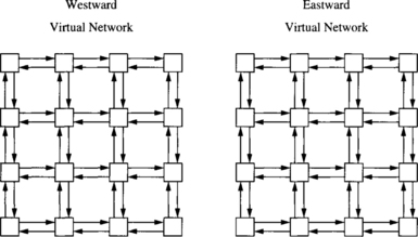
Solution As 180-degree turns are allowed, packets may cross a node several times. As a node cannot forward a packet destined for itself through the network, there exist allowed paths with forbidden subpaths. Thus, the routing function is not coherent.
The application of Theorem 3.1 to prove that the routing function is deadlock-free requires the definition of a routing subfunction. We will define it by defining the subset of channels C1 that can be supplied by the routing subfunction. In the eastward (westward) virtual network we have chosen the east and west channels plus the channels located on the east (west) edge of the mesh. The routing subfunction R1 defined by C1 is obviously connected. Also, packets introduced in the eastward (westward) virtual network cannot use channels from the other virtual network. Thus, there is not any channel dependency between channels of C1 that belong to different virtual networks. So, we only need to prove that the extended channel dependency graph for R1 in one virtual network has no cycles. We have chosen the eastward virtual network.
Figure 3.25 shows part of the extended channel dependency graph for R1 on a 3 × 3 mesh. The channels belonging to C1 are labeled as cij, where i and j are the source and destination nodes, respectively. Arcs represent channel dependencies; dashed arcs correspond to indirect dependencies. For the sake of clarity, we have only drawn two indirect dependencies. All the indirect dependencies are shown in Figure 3.26. There is not any cross-dependency. It can be seen that the graph is acyclic. Thus, R is deadlock-free.
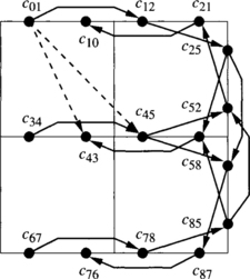
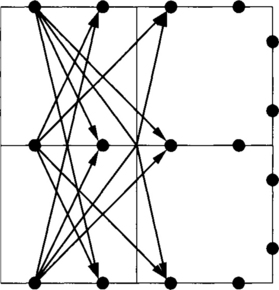
3.4. Consider a linear array of four nodes denoted ni, i = {0, 1, 2, 3}. Each pair of adjacent nodes is linked by two unidirectional channels. Let cHi, i = {0, 1, 2}, and cLi, i = {1, 2, 3}, be the outgoing channels from node ni that connect to higher-numbered nodes and lower-numbered nodes, respectively. Additionally, there is a unidirectional channel cA1 from n1 to n2 and a unidirectional channel cB2 from n2 to n1. Figure 3.27 shows the channel labeling. The routing function R is as follows: If the current node ni is equal to the destination node nj, store the packet. Otherwise, if the destination node nj is higher than the current node ni, use cHi,∀ j > i, or cA1 if ni = n1 or cB2 if ni= n2. If the destination node nj is lower than the current node ni, use cLi,∀j < i. If the network uses wormhole switching, show that R is not coherent. Prove that R is deadlock-free by showing that there is not any deadlocked configuration. Finally, show that there is not any routing subfunction satisfying the conditions proposed by Theorem 3.1.
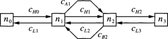
Solution Channel cB2 can only be used to send packets destined for higher-numbered nodes across n1. However, it cannot be used to send packets destined for lower-numbered nodes, like n1. Thus, R is not coherent.
There are two nested cycles in the channel dependency graph D for R. The first one is formed by channels cH1 and cB2. The second one is formed by channels cA1 and cB2. However, R is deadlock-free. Effectively, only packets destined for n3 are allowed to use cB2 and cH2. Thus, all the flits stored in the queue for cH2 can be delivered. We can try to fill the cycles by storing a single packet destined for n3 in the queues for channels cH1 and cB2; the latter contains the packet header. This packet can be forwarded through cA1. If the queue for cA1 contains flits, they must be destined for either n2 or n3. If the flits are destined for n2, the queue can be emptied. If they are destined for n3, there are two routing options at node n2: cB2 and cH2. cB2 is busy. However, cH2 is empty or it can be emptied. A similar analysis can be made if we start by storing a single packet destined for n3 in the queues for channels cA1 and cB2. Thus, there is not any deadlocked configuration.
Now, we have to define a connected routing subfunction R1. Obviously, channels cHi, i = {0, 1, 2}, and cLi, i = {1, 2, 3}, must belong to R1. Note that cH1 and cA1 have the same routing capabilities. So, any of them may be selected to belong to R1. Without loss of generality, we have chosen cH1 cB2 can only be used to send packets destined for n3. Thus, the only way to restrict routing on cB2 consists of removing it. If cB2 belongs to R1, then there are cycles in the extended channel dependency graph DE for R1 because there are direct dependencies from cH1 to cB2 and from cB2 to cH1. If cB2 does not belong to R1, then there are also cycles in DE because there is an indirect dependency from cH1 to cH1. It is produced by packets destined for n3 that cross cH1, then cB2, and then cH1 again. Even if we split the routing capabilities of cH1 among cH1 and cA1, the result is the same. Effectively, we can define R1 in such a way that cA1 can only be used by packets destined for n2, and cH1 by packets destined for n3. However, the indirect dependency from cH1 to cH1 still exists. Thus, there is not any connected routing subfunction satisfying the conditions proposed by Theorem 3.1.
3.5. Consider a 2-D mesh using the negative-first routing function [129]. This routing function R routes packets in such a way that west and south channels are used first, then switching to east and north channels. It is not possible to use west or south channels again after using east and/or north channel(s). Draw the channel dependency graph for R, group channels into equivalence classes, and draw the class dependency graph for R.
Solution Figure 3.28 shows the channel dependency graph for R on a 3 × 3 mesh. It also shows how channels are grouped into classes K0, K1, …, K7 as well as the class dependency graph for R. These graphs are valid for SAF, VCT, and wormhole switching.
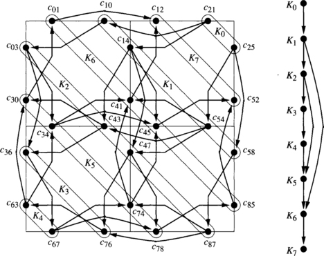
3.6. Consider a 2-D mesh using wormhole switching and without channel multiplexing (a single virtual channel per physical channel). The routing function R is minimal and fully adaptive. Design a deadlock recovery strategy based on Disha that allows simultaneous deadlock recovery and uses a single deadlock buffer per node.
Solution Let us assume that each node has one deadlock buffer. When a packet is waiting for longer than a threshold, it is assumed to be deadlocked. Some deadlocked packets are transferred to the deadlock buffer of a neighboring node. Those packets will continue using deadlock buffers until delivered. As we will see, not all the deadlocked packets can be transferred to a deadlock buffer. Those packets will be able to advance when the remaining deadlocked packets are delivered by using deadlock buffers.
First, we define the routing function for deadlock buffers. Let Q be the set of deadlock buffers. Consider a Hamiltonian path on the 2-D mesh and a node labeling according to that path. Figure 3.29 shows the path and node labeling for a 4 × 4 mesh. The routing function Rdb defined on deadlock buffers allows packets to reach nodes with a label greater than the current node label. This routing function is used when routing a packet header stored in a deadlock buffer. However, when a deadlock is detected, the packet header is stored in an edge buffer. In this case, it can be routed to the deadlock buffer of any neighboring node.
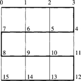
Now we have to prove that the deadlock recovery mechanism is able to recover from all deadlocked configurations. We use Theorem 3.1, extended as indicated in Section 3.2.3 to support edge buffers and central buffers. Thus, we need to define a connected routing subfunction R1, proving that it has no cycles in its extended channel dependency graph. Rdb is not connected. It only allows packets to reach nodes whose label is greater than the label of a neighboring node. Thus, we define a routing subfunction Redge that allows packets to reach nodes with a lower label. It is a routing subfunction of R and is defined by defining the subset of channels Cedge supplied by it. Figure 3.30 shows that subset for a 4 × 4 mesh. Let B1 = Q ∪ Cedge. The routing subfunction R1 defined by B1 is R1 = Redge ∪ Rdb. It is obviously connected.
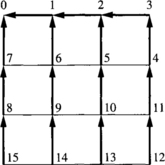
To prove that the extended channel dependency graph has no cycles, note that Rdb can only route packets by using deadlock buffers. Thus, there is not any dependency from deadlock buffers to edge buffers. Additionally, there is not any cyclic dependency between deadlock buffers because Rdb only uses deadlock buffers in increasing label order. Thus, we only need to prove that the extended channel dependency graph for Redge has no cycles. Figure 3.31 shows that graph for a 3 × 3 mesh. The channels belonging to Cedge are labeled as cij, where i and j are the source and destination nodes, respectively. As a reference, thin lines represent the mesh, also including node labeling. Solid arcs represent direct dependencies. Dashed arcs correspond to indirect dependencies. There is not any cross-dependency because Redge has been defined from a set of channels. The graph is acyclic. Thus, the deadlock recovery mechanism is able to recover from all deadlocked configurations.
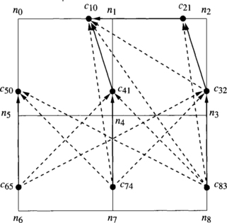
Problems
3.1. Draw the channel dependency graph for R1 defined in Example 3.5.
3.2. Extend the negative-first routing function defined in Exercise 3.5 for 2-D meshes by splitting each physical channel into two virtual channels. One set of virtual channels is used according to the negative-first routing function. The other set of channels is used for minimal fully adaptive routing. Is the routing function deadlock-free under wormhole switching? Is it deadlock-free when VCT is used?
3.3. Consider a 2-D mesh using the minimal west-first routing function [129]. This routing function routes packets in such a way that a packet traveling north or south cannot turn to the west. All the remaining turns are allowed, as far as the packet follows a minimal path. Extend the minimal west-first routing function by splitting each physical channel into two virtual channels. One set of virtual channels is used according to the minimal west-first routing function. The other set of channels is used for minimal fully adaptive routing. Is the routing function deadlock-free under wormhole switching? Is it deadlock-free when VCT is used?
3.4. Draw the extended class dependency graph for R1 defined in Exercise 3.3.
3.5. Consider a hypercube using wormhole switching. Each physical channel ci has been split into two virtual channels, ai and bi. The routing function R can be stated as follows: Route over any minimal path using the a channels. Alternatively, route in dimension order using the corresponding b channel. Prove that R is deadlock-free by using Theorem 3.1 and by using Theorem 3.3.
3.6. Consider a 2-D mesh. Physical channels are bidirectional full duplex. Each physical channel has been split into two virtual channels. North virtual channels are denoted as N1, N2; east channels as E1, E2; south channels as S1, S2; and west channels as W1, W2, respectively. Virtual channels are grouped into four virtual networks, according to Table 3.1. Packets introduced into a virtual network are routed using channels in the same virtual network until delivered. The routing function is minimal fully adaptive. Define the routing function on C × N. Define the routing function on N × N.
Table 3.1
Virtual networks and the associated virtual channels.
| Virtual Network | Channels |
| North-west | N1 and W2 |
| North-east | N2 and E1 |
| South-west | S2 and W1 |
| South-east | S1 and E2 |
3.7. Extend the routing function proposed in Exercise 3.6 so that it can be used in 3-D meshes.
3.8. Show that the routing function proposed in Exercise 3.6 for 2-D meshes cannot be used in 2-D tori. Draw a deadlocked configuration that cannot be recovered from.
3.9. Consider the 2-D mesh network depicted in Figure 3.32. This figure shows a single-cycle deadlock formed under minimal adaptive routing with one virtual channel per physical channel. The source and destination nodes of packet mi are labeled si and di, respectively. Draw the CWG depicting the deadlocked configuration. What is the deadlock set, resource set, and knot cycle density? Is there a packet in the CWG that, if eliminated through recovery resources, still does not result in deadlock recovery?
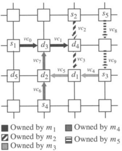
3.10. What is the minimum number of packets that can result in deadlock, assuming one virtual channel per physical channel and wormhole switching, in
![]() a unidirectional k-ary 1-cube?
a unidirectional k-ary 1-cube?
![]() a bidirectional k-ary 1-cube with minimal routing?
a bidirectional k-ary 1-cube with minimal routing?
![]() a unidirectional k-ary n-cube with nonminimal routing?
a unidirectional k-ary n-cube with nonminimal routing?
![]() a bidirectional k-ary n-cube with nonminimal routing?
a bidirectional k-ary n-cube with nonminimal routing?
3.11. Consider a 2-D torus using wormhole switching and without channel multiplexing. The routing function R is minimal and fully adaptive. Design a deadlock recovery strategy based on Disha that allows simultaneous deadlock recovery and uses two deadlock buffers per node.
1Deadlock recovery was referred to as deadlock detection in [321].
2Note that in Exercise 3.1, R uses the same channels used by R1 by adding more routing choices.
5Consider a boat with a hole in the hull. If water is not drained faster than it fills the boat, it will sink.