
EMBEDDED OPERATING SYSTEMS
This chapter discusses the implementation of embedded operating systems (OS). Because embedded operating systems are designed for a specific purpose, historically embedded operating systems were simple, time constrained, and operated in limited memory. This distinction has changed over time as the sophistication of embedded hardware has increased. Features, traditionally found on desktop computers, such as virtual memory, have migrated into the embedded system world.
Since this is a large subject, we have limited our scope to just the fundamental components that make up an embedded operating system. We also build on the firmware example shown in Chapter 10.
This chapter is divided into two sections: The first section takes you through the fundamental components that make up an embedded operating system and notes issues specific to ARM processors. The second section takes you through an example operating system called the Simple Little Operating System (SLOS). SLOS is designed to show an implementation of the fundamental components.
11.1 FUNDAMENTAL COMPONENTS
There is a common set of low-level components, each carrying out a prescribed action, that form an operating system. It is how these components interact and function that determines the characteristics of a specific operating system.
Initialization is the first code of the operating system to execute and involves setting up internal data structures, global variables, and the hardware. Initialization starts after the firmware hands over control. For hardware initialization an operating system sets up various control registers, initializes the device drivers, and, if the operating system is preemptive, sets up a periodic interrupt.
Memory handling involves setting up the system and task stacks. The positioning of the stacks determines how much memory is available for either the tasks or the system. The decision as to where the system stack is placed is normally carried out during operating system initialization. Setting up the task stack depends upon whether the task is static or dynamic.
A static task is defined at build time and is included in the operating system image. For these tasks the stack can be set up during operating system initialization. For example, SLOS is a static-task-based operating system.
A dynamic task loads and executes after the operating system is installed and executing and is not part of the operating system image. The stack is set up when the task is created (for example, as in Linux). Memory handling varies in complexity from one operating system to another. It depends upon a number of factors, such as the ARM processor core selected, the capabilities of the microcontroller, and the physical memory layout of the end target hardware.
The example operating system, SLOS, in Section 11.2 uses a static memory design. It simply configures a set of registers within the microcontroller and positions the stacks. Because there is no form of dynamic memory management, you will not find an implementation of malloc() and free(). These functions are normally found in the standard C library.
The method for handling interrupts and exceptions is part of the architecture design of the operating system. You have to decide how to handle the various exceptions: Data Abort, Fast Interrupt Request, Interrupt Request, Prefetch Abort, Reset, and Software Interrupt (SWI).
Not all of the exceptions require a handler. For instance, if you have a target board that does not use the FIQ interrupt, then a specific FIQ handler is not required. It is always safer to provide an infinite loop as a default handler for unused exceptions. This approach makes it easy to debug: when you break, it is clear that you have trapped at a specific handler. It also protects the system from unexpected exceptions.
A preemptive operating system like SLOS requires a periodic interrupt, which is normally produced by a counter/timer device on the target hardware. As part of the initialization stage, an operating system sets the periodic interrupt frequency. This is normally achieved by setting a specified value into one of the counter/timer memory-mapped registers.
When activated, the counter/timer will start to decrement this value. Once the value reaches zero, an interrupt is raised. This interrupt is then handled by the appropriate ISR for periodic interrupts. The ISR first reinitializes the counter/timer with a new start value and then calls either a scheduler or another specialized routine.
In contrast, a nonpreemptive operating system does not require a periodic interrupt and will use a different technique, for example, polling—the continuous checking for a state change in a device. If the device state changes, then a specific action can be connected to a particular state change.
The scheduler is an algorithm that determines which task is to be executed next. There are many scheduling algorithms available. One of the simplest is called a round-robin algorithm—it activates tasks in a fixed cyclic order. Scheduling algorithms have to balance efficiency and size with complexity.
Once the scheduler is complete, the new and old tasks have to be swapped with a context switch. A context switch saves all the old task registers from the processor into a data structure. Data for the new task is then loaded into the processor’s registers. (For more details on this procedure, take a look at Section 11.2.6.)
The last component is the device driver framework—the mechanism an operating system uses to provide a consistent interface between different hardware peripherals. The framework allows a standard and easy way of integrating new support for a particular peripheral into the operating system. For an application to access a particular peripheral there has to be a specific device driver available. The framework must provide a safe method of accessing the peripheral (for example, not allowing the simultaneous access of the same peripheral by more than one application).
11.2 EXAMPLE: SIMPLE LITTLE OPERATING SYSTEM
We have developed a small operating system we call the Simple Little Operating System (SLOS). It shows how the fundamental components discussed earlier come together in a complete operating system. We have chosen the ARM7TDMI since it is the simplest core in the ARM family. For a development environment we use the ARM Developers’ Suite version 1.2, and for a target the Evaluator-7T from ARM. It should be relatively easy to modify SLOS to build in other development environments. SLOS is loaded and executed using the Sandstone firmware described in Chapter 10.
SLOS is a preemptive operating system. A periodic interrupt activates a dormant task. For simplicity, all the tasks and device drivers are static; that is, they are created at build time and not while the system is running. SLOS also provides a device driver framework, discussed in Section 11.2.7.
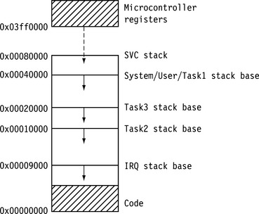
SLOS is designed to execute on an ARM7TDMI core with no memory management unit or protection unit. It is assumed that the memory map has already been configured by the initialization code (in this case, Sandstone, found in Chapter 10). SRAM is required to be located between 0x00000000 to 0x00080000, and the base configuration registers must be set to address 0x03ff0000.
SLOS is loaded at address 0x00000000, where the vector table is located. This is the same address as the entry point into SLOS. It is important that the ARM processor is in SVC mode when the firmware hands over control because SVC mode is a privileged mode and hence allows the initialization code to change modes by accessing the cpsr. We take advantage of this to set up the stacks in IRQ and system mode.
In this current configuration, SLOS includes three tasks and two service routines. Tasks 1 and 2 provide an example of mutual exclusion using a binary semaphore. The two service routines implemented are the periodic timer (which is essential) and a push-button interrupt (which is optional). Task 3 provides a simple command line interface through one of the ARM Evaluator-7T’s serial ports.
Each task in SLOS requires its own stack. All the tasks operate in user mode; thus, a task can read but not write to the cpsr. The only way a task can change to a privileged mode is to use an SWI instruction call. This is the mechanism used to call a device driver function, since a device driver may require full access to the cpsr.
The cpsr can be modified in a task, but only indirectly using an instruction that updates the condition flags.
11.2.1 SLOS DIRECTORY LAYOUT
SLOS can be found on our Web site under the Chapter 11 directory. The directory layout for SLOS is similar to the Sandstone firmware layout (see Figures 10.1 and 11.1).
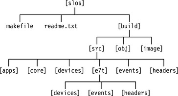
There are six subdirectories under slos/build/src that hold all the operating system source files. The slos/build/src/core directory includes the miscellaneous utility files, as well as the command line interpreter (CLI) sources.
Specific code for a platform is stored under a directory with the name of that platform. For instance, the code for the Evaluator-7T is stored under directory e7t.
The slos/build/src/e7t/devices directory holds all the device driver files, and the slos/build/src/e7t/events directory holds the files that handle services, exceptions, and interrupts.
Finally, the slos/build/src/apps directory holds all the applications/tasks for a particular configuration. For instance, for the Evaluator-7T implementation, there are three applications/tasks.
11.2.2 INITIALIZATION
There are three main stages of initializing SLOS—startup, executing process control block (PCB) setup code, and executing the C initialization code. The startup code sets up the FIQ registers and the system, SVC, and IRQ mode stacks. In the next stage, the PCB, which contains the state of each task, is set up, including all the ARM registers. It is used to store and restore task state during a context switch. The setup code sets the process control block to an initial start state. The final C initialization stage calls the device driver, event handler, and periodic timer initialization routines. Once complete, the first task can be invoked.
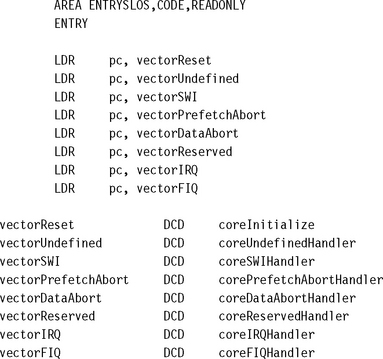
Control is passed to SLOS through the reset vector. The vectorReset is a location in memory that holds the start address of the initialization code. It is assumed that the firmware has left the processor in SVC mode, which allows the operating system initialization code to have full access to the cpsr. The first operating system instruction loads the pc with the start address of the initialization code, or coreInitialization. You can see from the vector table, shown here, that this instruction loads a word using the load pc-relative instruction. The assembler tool has already calculated the offset value using the difference between the pc and the address of the vectorReset.
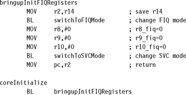
As part of the initialization process we have implemented a low-level debug system using the banked FIQ mode registers, as shown here. These registers are used to store status information. It is not always possible to use FIQ registers since they may be used for another purpose.
The next stage is to set up the SVC, IRQ, and System base stack registers. For the SVC stack, this is straightforward since the processor is already in SVC mode. The code is
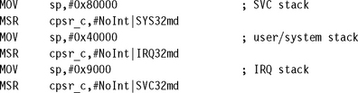
As you can see from the code, once the stacks are set up, the processor is switched back into SVC mode, which allows the rest of the initialization process to continue. Being in privileged mode allows the final initialization stage to unmask the IRQ interrupt by clearing the I bit and changing the processor to user mode.
The results of executing the startup code are the following:
To start SLOS running, the PCB for each task has to be initialized. A PCB is a reserved data structure and holds a copy of the entire ARM register set (see Table 11.1). A task is made active by copying the appropriate task’s PCB data into the processor registers.
Table 11.1
| Offset | Registers |
| 0 | — |
| −4 | r14 |
| −8 | r13 |
| −12 | r12 |
| −16 | r11 |
| −20 | r10 |
| −24 | r9 |
| −28 | r8 |
| −32 | r7 |
| −36 | r6 |
| −40 | r5 |
| −44 | r4 |
| −48 | r3 |
| −52 | r2 |
| −56 | r1 |
| −60 | r0 |
| −64 | pc + 4 |
| −68 | spsr |
The PCB of each task has to be set up prior to a context switch occurring since the switch will transfer the PCB data into registers r0 to r15 and cpsr. Left uninitialized, the context switch will copy garbage data into these registers.
There are four major parts of the PCB that have to be initialized: the program counter, the link register, the user mode stack, and the saved processor status register (in other words registers r13, r14, r15, and the spsr) for each task.
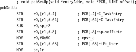
To help illustrate this, we have extracted the routine for initializing PCBs. The routine pcbSetUp is called to set up tasks 2 and 3. Register r0 is the task entry address—label entryAddr. This is the execution address for a task. Register r1 is the PCB data structure address—label pcbAddr. This address points into a block of memory that stores the PCB for a task. Register r2 is the stack offset and is used to position the stack in the memory map. Note that task 1 does not require initialization since it is the first task to be executed.
The final part of setting up the PCBs is to set up the current task identifier, which is used by the scheduling algorithm to determine which task is to be executed.
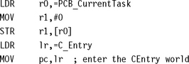
At the end of the code fragment the first C routine—C_Entry—is called by setting the pc to the start address of the routine.
The results of executing the PCB setup code are the following:
![]() Initialize the PCB for all three tasks.
Initialize the PCB for all three tasks.
![]() Set the current PCB to be executed as task 1 (identifier 0).
Set the current PCB to be executed as task 1 (identifier 0).
Initialization is now handed over to the C_Entry() routine, which can be found in build/src/core/cinit.c file. The C_Entry routine calls another routine, cinit_init(). This routine, shown here, initializes the device drivers, services, and finally the periodic interrupt tick. The C code has been designed so it does not require the standard C library to be initialized because it does not call any standard C library functions such as printf(), fopen(), and so on.
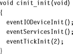
The functions eventIODeviceInit, eventServicesInit, and eventTickInit are all called to initialize the various specific parts of the operating system. You will notice that eventTickInit has a single parameter with the value 2. This is used to set the number of milliseconds between periodic tick events.
After initialization is complete, the periodic timer can be started, as shown here. This means that task 1 needs to be called before the first timer interrupt. To allow for the periodic event to interrupt the processor, the IRQ has to be enabled and the processor has to be placed into user mode. Once this is accomplished, the address of the entry point for task 1, C_EntryTask1, is then called.
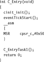
If everything is working correctly, the return at the end of C_Entry routine will never be executed. At this point all initialization is complete and the operating system is fully functional.
The results of executing all the C initialization code are the following:
11.2.3 MEMORY MODEL
We have adopted a simple memory model for SLOS. Figure 11.2 shows that the code portion of SLOS, including the tasks, are located in low memory, and the stacks for the IRQ and for each task are located in higher memory. The SVC stack is set at the top of memory. The arrows in the memory map show the direction of stack growth.
11.2.4 INTERRUPTS AND EXCEPTIONS HANDLING
In this implementation of the operating system only three exceptions are actually used. The other exceptions are ignored by going to specific dummy handlers, which for safety reasons are implemented as infinite loops. For a complete implementation these dummy handlers should be replaced with full handlers. Table 11.2 shows the three exceptions and how they are used within the operating system.
Table 11.2
| Exception | Purpose |
| Reset | initialize the operating system |
| SWI | mechanism to access device drivers |
| IRQ | mechanism to service events |
11.2.4.1 Reset Exception
The reset vector is only called once during the initialization phase. In theory, it could be called again to reinitialize the system—for example, in response to a watchdog timer event resetting the processor. Watchdog timers are used to reset a system when prolonged inactivity occurs.
11.2.4.2 SWI Exception
Whenever a device driver is called from an application, the call goes through the SWI handler mechanism. The SWI instruction forces the processor to change from user to SVC mode.
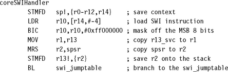
The core SWI handler is shown here. The first action of the handler is to store registers r0 to r12 to the SVC stack.
The next action calculates the address of the SWI instruction and loads that instruction into register r10. The SWI number is obtained by masking the top 8 bits. The address of the SVC stack is then copied into register r1 and is used as the second parameter when calling the SWI C handler.
The spsr is then copied to register r2 and stored on the stack. This is only required when a nested SWI call occurs. The handler then jumps to the code that calls the C handler routine.
The code that follows the BL instruction returns back to the callee program as shown here. This is achieved by restoring the spsr from the stack and loading all the user banked registers back, including the pc.
![]()
The link register has been set in the BL instruction. This code is executed when the SWI C handler is complete.
![]()
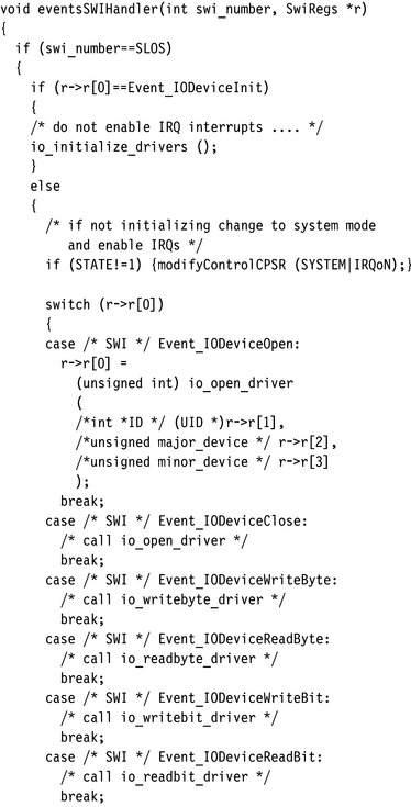
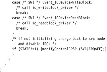
The C handler, eventsSWIHandler, shown in Figure 11.3, is called with register r0 containing the SWI number and register r1 pointing to the registers stored on the SVC stack.
11.2.4.3 IRQ Exception
The IRQ handler is a lot simpler than the SWI handler. It is implemented as a basic nonnested interrupt handler. The handler first saves the context and then copies the contents of the interrupt controller status register, INTPND, into register r0. Each service routine then compares register r0 with a particular interrupt source. If the source and interrupt match, then the service routine is called; otherwise the interrupt is treated as being a phantom interrupt and ignored.
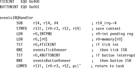
For a known interrupt source an interrupt veneer is called to service the event. The following code shows an example timer veneer. You can see from the example that the veneer includes calling two routines: The first resets the timer, eventsTickService (platform-specific call), and the second, kernelScheduler, calls the scheduler, which in turn calls a context switch.
![]()
There is no requirement to have registers r4 to r12 on the IRQ stack, since the scheduling algorithm and the context switch handle all the register details.
11.2.5 SCHEDULER
The low-level scheduler, or dispatcher, used in SLOS is a simple static round-robin algorithm as illustrated in the following pseudocode. “Static” in this case means that the tasks are only created when the operating system is initialized. Tasks in SLOS can neither be created nor destroyed when the operating system is active.
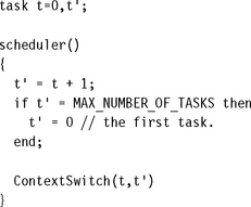
As stated previously, the current active task t, PCB_CurrentTask, is set to 0 during the initialization phase. When the periodic tick interrupt occurs, the new task t’ is calculated from the current task t plus 1. If this task number equals the task limit, MAX_NUMBER_OF_TASKS, then task t’ is reset to the start 0.
Table 11.3 is a list of the labels used by the scheduler and a description of how they are used in the algorithm. These labels are used in the following procedure and code for the scheduler:
Table 11.3
| Label | Description |
| PCB_CurrentTask | contains the current task t |
| PCB_Table | table of address pointers to each task PCB |
| PCB_PtrCurrentTask | pointer to the current task t |
| PCB_PtrNextTask | pointer to the next task t’ |
| PCB_IRQStack | temporary storage for the IRQ stack (context switch) |
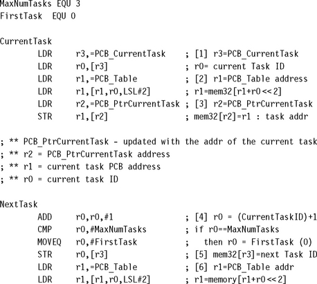
1. Obtain the current task ID by loading the contents of PCB_CurrentTask.
2. Find the corresponding PCB address of the current task by using the PCB_CurrentTask as the index into the PCB_Table.
3. Use the address obtained in stage 2 to update the value in the PCB_PtrCurrentTask.
4. Calculate the new task t’ ID using the round-robin algorithm.
5. Store the new task t’ ID into PCB_CurrentTask.
6. Find the address of the next task PCB by indexing into the PCB_Table using the updated PCB_CurrentTask.
The code scheduling the next task t’ is:
![]()
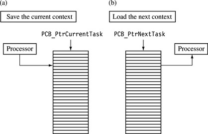
11.2.6 CONTEXT SWITCH
Using the updated information produced by the scheduler, the context switch then swaps the active task t with the next task t’. To achieve this, a context switch splits the activity into two stages, as shown in Figure 11.4. The first stage involves saving the processor registers into the current task t PCB pointed by PCB_PtrCurrentTask. The second stage loads the registers with data from the next t’ PCB pointed by PCB_PtrNextTask.
We will now take you through the procedure and code of the two stages of the context switch, detailing the saving of the current context first, followed by loading a new context.
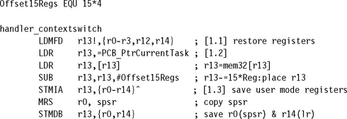
11.2.6.1 Save the Current Context
The first stage is to save the current registers of the active task t. All tasks execute in user mode, so the user mode registers have to be saved. Here is the procedure:
1. We must restore registers r0 to r3 and r14 from the stack. These registers belong to the current task.
2. Register r13 is then used to point into the PCB of the current task PCB_CurrentTask offset by −60. This offset allows two instructions to update the entire PCB.
3. The final action of the first stage is to store all the user bank registers r0 to r14. This occurs in a single instruction. Remember that the ![]() symbol means that the store multiple acts on the user mode registers. The second store instruction saves the spsr and the returning link register.
symbol means that the store multiple acts on the user mode registers. The second store instruction saves the spsr and the returning link register.
The code for saving the registers to a PCB is
The results of saving the current context are the following:
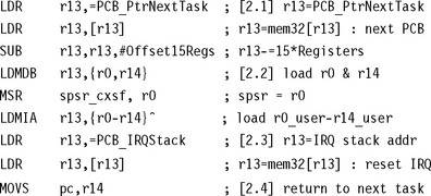
11.2.6.2 Load the Next Context
The second stage of the context switch involves transferring the PCB for t’ into the banked user mode registers. Once complete, the routine then must hand over control to the new task t’. Here is the procedure:
1. Load and position register r13 at offset −60 from the start of the new PCB.
2. Load register spsr and the link register first. Then the next task registers r0 to r14 are loaded. Register r14 is the user bank register r14, not the IRQ register r14 shown by ![]() in the instruction.
in the instruction.
3. The IRQ stack is then restored from PCB_IRQStack.
4. The new task is resumed by copying the address held in register r14 into the pc and updating the cpsr.
The code for loading the registers from a PCB is
11.2.7 DEVICE DRIVER FRAMEWORK
The device driver framework (DDF) is implemented using SWI instructions. The DDF protects the operating system from applications accessing hardware directly and provides a uniform standard interface for the tasks. For a task to access a particular device it must first obtain a unique identification number (UID). This is achieved by calling the open macro, or eventsIODeviceOpen. This macro is translated directly into a device driver SWI instruction. The UID is used to check that another task has not already accessed the same device.
The task code for opening a device driver is
![]()
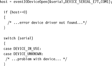
The example shows a serial device being opened using the device driver framework.
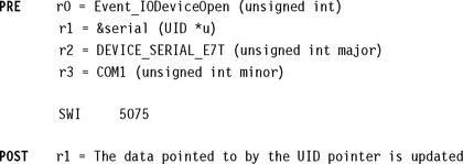
A set of macros translates the arguments into registers r1 to r3. These registers are then passed through the SWI mechanism to the device driver function. In the example, only the value pointed to by r1, &serial, is actually updated. This value is used to return the UID. If the value returned is zero, then an error has occurred.
The following code shows how the macro eventIODeviceOpen is transformed into a single SWI instruction call:
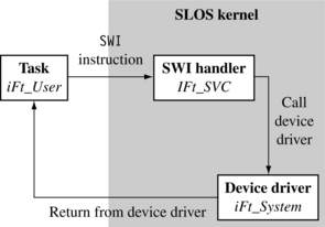
The SWI interface is used as a method of changing to a privileged mode when the task executes in a nonprivileged mode. This allows the device driver to gain full access to the cpsr. Figure 11.5 shows the actual mode changes when a device driver function is called. You can see from the diagram that the device driver itself executes in system mode (which is privileged).
Once an SWI instruction is executed, the processor enters SVC mode and IRQ interrupts are automatically disabled. Interrupts are only reenabled when the processor changes to system mode. The only exception to this is when a device driver function is called during the initialization phase; in this case, interrupts will remain disabled.
11.3 SUMMARY
The fundamental components that make up an embedded operating system executing on an ARM processor are the following:
![]() The initialization sets up all of the internal variables, data structures, and hardware devices used by the operating system.
The initialization sets up all of the internal variables, data structures, and hardware devices used by the operating system.
![]() Memory handling organizes the memory to accommodate the kernel plus the various applications to be executed.
Memory handling organizes the memory to accommodate the kernel plus the various applications to be executed.
![]() All interrupts and exceptions require a handler. For unused interrupts and exceptions, a dummy handler must be installed.
All interrupts and exceptions require a handler. For unused interrupts and exceptions, a dummy handler must be installed.
![]() A periodic timer is required for preemptive operating systems. The timer produces an interrupt that causes the scheduler to be called.
A periodic timer is required for preemptive operating systems. The timer produces an interrupt that causes the scheduler to be called.
![]() A scheduler is an algorithm that determines the new task to be executed.
A scheduler is an algorithm that determines the new task to be executed.
![]() A context switch saves the state of the current task and loads the state of the next task.
A context switch saves the state of the current task and loads the state of the next task.
These components are exemplified in the operating system called the Simple Little Operating System (SLOS):
![]() Initialization—The initialization sets up all the functions of SLOS, including the bank mode stacks, process control blocks (PCB) for each application, device drivers, and so on.
Initialization—The initialization sets up all the functions of SLOS, including the bank mode stacks, process control blocks (PCB) for each application, device drivers, and so on.
![]() Memory model—The SLOS kernel is placed in lower memory, and each application has its own storage area and stack. The microcontroller system registers are placed away from the ROM and SRAM.
Memory model—The SLOS kernel is placed in lower memory, and each application has its own storage area and stack. The microcontroller system registers are placed away from the ROM and SRAM.
![]() Interrupts and exceptions—SLOS makes use of only three events. These events are Reset, SWI, and IRQ. All the other unused interrupts and exceptions have a dummy handler installed.
Interrupts and exceptions—SLOS makes use of only three events. These events are Reset, SWI, and IRQ. All the other unused interrupts and exceptions have a dummy handler installed.
![]() Scheduler—SLOS implements a simple round-robin scheduler.
Scheduler—SLOS implements a simple round-robin scheduler.
![]() Context switch—First the current context is saved into a PCB, and then the next task context is loaded from a PCB.
Context switch—First the current context is saved into a PCB, and then the next task context is loaded from a PCB.
![]() Device driver framework—This protects the operating system from applications accessing hardware directly.
Device driver framework—This protects the operating system from applications accessing hardware directly.