This chapter includes the following topics:
The first step in overcoming network barriers to enabling high-performance access to remote files, content, applications, and data over the WAN is to ensure that the resources of the WAN are aligned with the appropriate business priority. By aligning network resources with business priority, you can ensure that specific applications that are critical to the business are given the appropriate levels of bandwidth and response time in terms of network transmission throughput. These factors are, of course, limited by the capabilities of the physical network itself.
Aligning network resources with business priority allows IT organizations to identify network consumers, prioritize traffic accordingly, and apply policy. For instance, an IT organization may want to make sure that Voice over IP (VoIP) calls are guaranteed a minimum of 30 percent of the available bandwidth capacity on the WAN (based on the bandwidth per call and the number of expected calls), and ensure that unsanctioned Internet traffic never consumes more than 10 percent of available bandwidth capacity.
Furthermore, policy may also dictate that intermediary network devices handle traffic such as VoIP, which is sensitive to network latency and jitter, in such a way as to accommodate their low-latency requirements (for example, low-latency queuing and interleaving). To do this, IT organizations must first employ network visibility mechanisms to identify traffic on the network, followed by network control mechanisms to ensure that applications are given the right level of service on the network.
IT organizations need to determine which applications are using the network, how the network is being used, and how much of the network each consumer or application should consume. Many IT organizations find that a large percentage of their network bandwidth is consumed by unsanctioned applications, such as instant messaging, peer-to-peer file sharing, or general web surfing. When bandwidth capacity is added to the network, many IT organizations find that only a fraction of the additional capacity goes to the applications that were in need of the extra capacity, and the remainder provides more capacity for those using unsanctioned applications, thereby wasting the majority of the expenses incurred to upgrade the network.
Leveraging visibility to enable classification, prioritization, and control helps to ensure that network resources are aligned with business objectives and that applications and consumers receive the level of service from the network that they need. Employing such policy is a good practice for traditional network implementations and is foundational to employing accelerator devices, which can integrate and leverage these technologies as well.
Because many authoritative resources focus on technologies such as quality of service (QoS), Network Based Application Recognition (NBAR), NetFlow, and other features, this chapter serves as an overview to these technologies relative to how you can employ them to align network resources with business priority and application requirements. The latter part of the chapter provides an introduction to accelerators and how you can deploy them in conjunction with these value-added network services to provide end-to-end acceleration, control, prioritization, and visibility.
Many network administrators today still do not know what type of traffic is consuming network capacity, what the top applications are, and who the top talkers are. Most routers, switches, and other network devices today include feature sets that provide network administrators with the information necessary to examine how the network is being used. Some of these feature sets provide real-time analysis of network utilization, and others provide a historical view of network utilization. Both types of data enable the network administrator to prove and establish a baseline for network utilization.
This section examines two commonly used mechanisms, NetFlow and NBAR, for viewing network utilization characteristics at a very granular level. Once collected, this data is useful to network administrators not only to get a better grasp on how the network is being used, but also to choose relative priority among applications, data, and nodes that consume network capacity.
NetFlow is a set of instrumentation tools, pioneered by Cisco, that allows network administrators to characterize network operation and utilization. NetFlow was developed and patented by Cisco in 1996 as NetFlow version 1. NetFlow v1 provided basic characterization of flows based on the common 5-tuple (source and destination IP addresses, source and destination TCP ports, and IP protocol).
NetFlow has evolved into a more robust system of flow characterization, NetFlow v5, which is the most commonly used version of NetFlow today. NetFlow v6 added additional details related to encapsulation. NetFlow v7 provided extensions to support the Catalyst 5000 family switch with a NetFlow feature card (NFFC) installed. NetFlow v8 provided enhancements necessary to enable router-based aggregation. Router-based aggregation allows the router to group multiple traditional flows together, thereby minimizing router resource utilization.
NetFlow v9, the latest version of NetFlow at the time of this writing, provides a flexible and extensible export format. NetFlow v9 (RFC 3954) accommodates new NetFlow-supported technologies such as IP Multicast, Multiprotocol Label Switching (MPLS), Network Address Translation (NAT), and Border Gateway Protocol (BGP). Given the widespread adoption of NetFlow, NetFlow v9 became the foundation for the IP Flow Information Export (IPFIX) standard, which can be found as RFC 3917.
NetFlow allows network administrators to have visibility into the network, which is necessary to better understand the following:
Applications and network utilization: Enables network administrators to examine a history of traffic flows to determine how many flows exist between connected nodes and the amount of bandwidth capacity being utilized between them.
Overall network capacity consumption: Allows network administrators to better understand how much of the network is being utilized holistically to determine if additional capacity is required to support productivity and business-critical applications.
NetFlow is primarily used for baselining application requirements and network utilization for the purpose of determining what configuration of prioritization and control should be employed. NetFlow can also be used to assess the impact of changes to the network, assess network anomalies, identify security vulnerabilities, provide facilities for charge-back and bill-back, diagnose network performance problems (such as bandwidth “hogs”), and access monitoring. Given the focus of this book on application performance, these capabilities of NetFlow are not discussed.
NetFlow operation involves two key components:
A NetFlow-enabled device
A NetFlow collector
A NetFlow-enabled device (which includes most routers and switches), when configured, keeps a cache of IP flows that have traversed that device. An IP flow is a series of packets with matching packet attributes. An IP flow generally includes five attributes and up to a maximum of seven attributes, as follows:
Source IP address: The source IP address within the packet being transmitted
Destination IP address: The destination IP address within the packet being transmitted
IP protocol number and type: The protocol as defined by the IP packet header (that is, TCP, UDP, ICMP, or others)
Source port: The source port number of the Layer 4 header
Destination port: The destination port number of the Layer 4 header
Type of service (ToS) identifier: The bits tagged within the type of service, or ToS, byte within the IP header, denoting priority
Router or switch interface: The interface at which the packet from the flow was received
When packets with matching attributes are identified on an interface configured for NetFlow, they are grouped internally by the NetFlow device and counters are generated and maintained against the matching packets. This information is stored in a NetFlow cache and contains details about each of the identified flows and counter data related to those flows. Furthermore, additional information can be gathered about these flows, including:
Timestamps: Help to determine the longevity of the flow to provide analysis and summarization of traffic and network utilization based on the time of day
Next-hop information: Includes the next-hop IP address and routing protocol–specific information such as the BGP autonomous system (AS)
Subnet mask: Used to determine the network that the flow is related to
TCP flags: Bits contained within the TCP header that identify handshakes and other signaling, including synchronization and resets
You can examine this information in real time using a device’s CLI or GUI, which is helpful in troubleshooting and examining real-time utilization. You also can configure the device to export flows in the cache that have terminated to a node on the network (typically a PC or a server) that is configured to receive export packets containing NetFlow data, commonly called a NetFlow collector.
Exporting terminated flows (that is, when a TCP connection is torn down) to a NetFlow collector is helpful because it not only enables long-term retention of statistics related to previously seen flows for offline analysis, reporting, and baselining, but also removes the need for the network device itself (that is, a router or switch) to maintain this data long-term, thereby ensuring precious NetFlow device resources are kept relatively free. These flows are exported to the NetFlow collector using UDP packets and typically contain information for 30 to 50 flows at a time.
Figure 3-1 shows the process of NetFlow collection on a router with export to a collector. Figure 3-2 shows a more granular view of the data collected by NetFlow.
Many applications exist that allow for in-depth and thorough analysis of NetFlow data, including products from Cisco, CA, Hewlett-Packard, InfoVista, NetQoS, and many others. These applications are helpful in analyzing the data presented by NetFlow and correlating the data into various reports, including these:
Top talkers: The nodes that consume the most bandwidth
Top applications: The applications that consume the most bandwidth
Many of these applications also couple other mechanisms for analyzing performance metrics such as Simple Network Management Protocol (SNMP) polling, remote monitoring (RMON), and traffic analysis using port mirroring. For example, Figure 3-3 shows a report generated using NetQoS SuperAgent that provides insight into who the top talkers on a given network are.
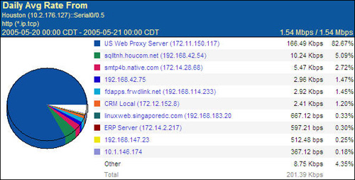
Figure 3-4 shows another report generated by NetQoS SuperAgent that displays the top applications found on the network.
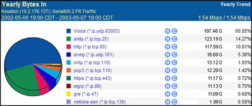
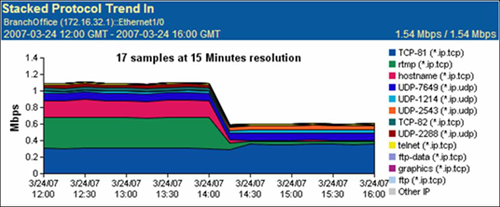
Figure 3-5 shows a NetQoS SuperAgent report that displays network utilization trends over a 4-hour period, and a breakdown of which applications were identified during each sample period. More information about NetQoS can be found at http://www.netqos.com.
With the information provided by NetFlow, network administrators can begin to fully understand how the network is being utilized, which applications are consuming network resources at what time of day, and which nodes are consuming the most available network capacity. Then, they can begin the process of classification and prioritization.
For more information on Cisco IOS NetFlow, including a detailed technical overview, visit http://www.cisco.com/go/netflow.
NBAR is another mechanism that network administrators can employ on network devices such as routers or switches to automatically discover application protocols and collect statistics. You can use NBAR in conjunction with NetFlow to provide a more granular view of specific applications that are using the network. While NetFlow examines primarily Layer 3 (network) and Layer 4 (transport) information to quantify network consumption on a flow-by-flow basis, NBAR examines data not only at Layer 4 (transport layer, port identification), but also all the way up to Layer 7 (application layer).
NBAR provides deep packet inspection (DPI) capabilities to classify and quantify application-specific network utilization. This means that NBAR can go beyond examination of traditional IP address and port information and examine the payload of traffic flows to identify the application that is being transported across the network. This allows NBAR to uniquely classify and differentiate application traffic within a shared connection (for instance, a print job within a remote desktop session). Figure 3-6 shows a comparison of NBAR and NetFlow in terms of which aspects of network traffic each can examine.
While both NetFlow and NBAR provide flow identification at Layer 3 and Layer 4, each provides a different set of capabilities that are useful to a network administrator who wishes to align network resources with relative business and application priority. NetFlow is helpful in tracking the longevity of flows on the network and providing the data necessary to analyze network utilization characteristics. NBAR provides administrators with an application-based view rather than a network-based view, yielding insight into which applications are actually the consumers of the available network resources. NBAR is used not only for visibility into application flows traversing a network, but also to provide traffic classification necessary to employ QoS actions.
Note
The following list summarizes applications that NBAR is able to recognize. For more information on Cisco IOS NBAR, including a detailed technical overview, visit http://www.cisco.com/go/nbar.
Security and Tunneling | Network Mail Services | Internet | |
|---|---|---|---|
Citrix ICA | GRE | IMAP | FTP |
pcAnywhere | IPINIP | POP3 | Gopher |
Novadigm | IPsec | Exchange | HTTP |
SAP | L2TP | Notes | IRC |
Routing Protocols | MS-PPTP | SMTP | Telnet |
BGP | SFTP | Directory | TFTP |
EGP | SHTTP | DHCP/BOOTP | NNTP |
EIGRP | SIMAP | Finger | NetBIOS |
OSPF | SIRC | DNS | NTP |
RIP | SLDAP | Kerberos | |
Network Management | SNNTP | LDAP | X-Windows |
ICMP | SPOP3 | Streaming Media | Peer-to-Peer |
SNMP | STELNET | CU-SeeMe | BitTorrent |
Syslog | SOCKS | Netshow | Direct Connect |
RPC | SSH | Real Audio | eDonkey/eMule |
NFS | Voice | StreamWorks | FastTrack |
SUN-RPC | H.323 | VDOLive | Gnutella |
Database | RTCP | RTSP | Kazaa |
SQL*NET | RTP | MGCP | WinMX |
Microsoft SQL Server | SIP | Signaling | |
SCCP/Skinny | RSVP | ||
Skype |
The previous section presented two means of examining the network to gather a fundamental understanding of how the network is being used. This information forms the foundation from which you can make decisions about how to align network resources to accommodate the relative priority of applications and hosts that are using the network. This information is also important to ensure that the network is configured in such a way that it provides the appropriate levels of handling and control based on application and business requirements.
Using information gathered through NetFlow or other mechanisms (for instance, network analysis modules or accelerators with monitoring capabilities, both of which generally provide similar reporting capabilities), network administrators can then define what levels of service need to be applied to different types of traffic and how this data should be handled. These same tools also serve as a means of validation after such policies have been implemented within the network to verify that the application requirements and business priority definitions are being met.
Without QoS, best-effort handling is provided to all flows on the network, thereby introducing the possibility that noncritical traffic may delay or block the service of business-critical traffic or traffic from applications that have sensitivities to network characteristics such as latency or loss. With best-effort handling, all traffic is considered equal, as shown in Figure 3-7. In this figure, peer-to-peer sharing consumes all the available network resources, leading to bandwidth starvation for the applications that need precious WAN bandwidth to drive user productivity. Such situations could quickly lead to employee frustration with business applications, loss of revenue, poor morale, and job dissatisfaction.
With QoS configured, appropriate handling can be provided to traffic flows based on classification and priority. As shown in Figure 3-8, the result is that the business-critical applications that demand bandwidth and service on the network are unimpeded even when unsanctioned traffic is present. In this example, peer-to-peer sharing is shown as being permitted, and it should be noted that such applications could be blocked altogether.
Note
Figure 3-8 shows peer-to-peer sharing as permitted, however, this traffic could be blocked rather than permitted.
With QoS in place, network administrators are able to better allocate available network capacity to those applications that need it the most. This allocation of network resources with business priority helps to ensure precious network capacity is used by sanctioned applications, thereby encouraging user productivity.
The QoS architecture is built around a behavioral model that comprises the following four key functions, each of which is outlined in the following sections. These functions provide the facilities necessary to align network resources with business priority and application requirements.
Classification: Identifies application and traffic flows on the network. Once identified, further action and specific handling can be applied to the flow.
Pre-queuing: Includes operations that are performed against flows prior to consuming network device (router or switch) resources such as queues. The operations include dropping packets (undesirable flows), traffic conditioning (policing), and marking relative priority on the packets themselves.
Queuing and scheduling: Enforce priority of selected packet streams through the use of configurable queuing mechanisms, such as high-priority handling of delay-sensitive traffic, selective delay of lower-priority traffic during periods of congestion, traffic conditioning (shaping), and enforcement of bandwidth allocation.
Post-queuing: Improves link throughput using optional operations such as packet compression, header compression, and link fragmentation and interleaving (LFI).
The behavioral model provides the facilities necessary to align network resources to business priority and to optimize user productivity over the network. Figure 3-9 shows an example.
Packet classification allows a network device (such as a router, a switch, or even an accelerator) to partition network traffic into multiple priority levels or classes of service based on a variety of match conditions. These match conditions help the network device to differentiate flows from one another based on packet, flow, or application characteristics. With regard to the QoS behavioral model, as packets enter a device, they undergo classification such that the device is able to discern what application the flow represents and how to appropriately handle that traffic. This serves as the foundation by which a device can provide differentiated service among equal or unequal flows.
Most network devices provide an array of match conditions that can be used to examine traffic for purposes of classification. The most common classifiers include the following:
Access control lists (ACL): ACLs (standard, extended, or otherwise) allow for explicit permission or denial of a packet to be matched based on the match conditions defined within the ACLs as parameters. These match conditions include IP protocol number, routing protocol parameters, ICMP, IGMP, source or destination IP address, source or destination TCP or UDP port assignment, and more. Some of these characteristics can be used as match conditions without the use of an ACL. These match conditions are the most frequently used, as they cover nearly the entire set of Layer 3 and Layer 4 parameters used by a packet or flow.
MAC address: The link layer addresses contained in the frame being examined by the network device can be used as a match condition for classification.
VLAN identifier: The VLAN ID of a tagged frame can be used as a match condition to identify which VLAN a packet was received on. This allows for differentiated handling of packets and flows based on VLAN.
Input interface: The interface that the packet was received from on the network device itself can be used as a match condition. This allows for differentiated handling of packets and flows based on the physical interface being used.
Previous DSCP/ToS settings: Previously marked differentiated services code point (DSCP) bits within the type of service (ToS) field can be used for packet classification for packets received by the network device.
Class of service: The class of service (CoS) bits previously marked within a link layer header can be used as a means of classification.
Packet length: The length of the packet received can be used as a classifier. For instance, it may be desirable to classify small packets and large packets to adjust the way the network device handles packets based on their size.
NBAR: NBAR is used not only for protocol discovery and to identify which applications are found on the network, but also to provide classification for those applications. NBAR, when used for classification, can provide standard Layer 4 classification (based on port identification) or Layer 7 classification (by examining the payload of a packet).
Once packets have been classified, the next set of functions in the QoS behavior model, pre-queuing operations, are employed. Pre-queuing operations are employed before queue capacity in the network device is consumed. Pre-queuing operations ensure that queue capacity is used only by those application flows that are sanctioned on the network. Pre-queuing operations can also result in the marking, or coloring, of packets, which allows the network device itself, along with any upstream intermediary network device that uses the same coloring scheme, to correctly understand the relative priority and handling requirements of the packets being received. In addition to packet marking, pre-queuing operations include packet dropping and policing.
Packet marking involves the manipulation of a 1-byte (8-bit) field within the IP packet header called the type of service, or ToS, byte. Network devices use this byte of data to determine the relative priority and handling requirements of incoming packets. The ToS byte contains data for one of two widely adopted mechanisms:
Integrated Services (IntServ)
Differentiated Services (DiffServ)
In either case, a series of bits is flagged within the ToS byte to identify the relative priority and handling requirements of the packet. Accurate handling of marked packets can be ensured only when adjacent devices are in agreement about how packets are handled based on their marking. Figure 3-10 shows the IP packet header containing the ToS byte.
IntServ is commonly referred to as hard QoS due to its ability to set flags related to reliability, bandwidth, and latency and also its reliance on the Resource Reservation Protocol (RSVP) to signal and reserve the desired QoS for each flow in the network. IntServ uses the first 3 bits of the ToS byte for IP Precedence (priority) and the remaining 5 bits to define the need for maximum reliability, throughput, minimum delay, and cost. The first 3 bits used by IntServ represent up to eight levels of relative priority. Table 3-1 shows the defaults for these levels, with the lower values representing lower levels of priority.
IntServ requires configuration of intermediary network devices and end nodes, and as such can be seen as a complex end-to-end system to configure in light of its capabilities. Network utilization can increase slightly due to the overhead of refreshing the end-to-end QoS policy and maintenance of state information at each network device in the path, which hinders scalability. Due to the complexity of implementing IntServ, many organizations have chosen to implement DiffServ as a less complicated alternative. However, given IntServ’s robust capabilities, it is still considered the strongest solution for providing end-to-end QoS.
DiffServ is more commonly used than IntServ and is referred to as soft QoS due to its reliance on per-hop behaviors at each node in the network, dictated largely by a common understanding and configuration of how to handle traffic based on the applied marking. The result is far less network overhead and resource utilization, because the configuration can remain largely static and does not require constant synchronization.
Furthermore, bandwidth and handling do not need to be requested from each node within the network. Rather, predefined per-hop behavior dictates the handling of classified traffic at each hop. In this way, DiffServ is often referred to as the more efficient and more scaleable end-to-end QoS model when compared to IntServ. Unlike IntServ, which uses 5 bits of the ToS byte for signaling and control flags, DiffServ does not use control flags, thereby allowing it to consume a larger quantity of bits within the ToS byte and providing a greater degree of differentiation. DiffServ uses 6 bits of the ToS byte, thereby allowing for up to 64 differentiated levels of traffic. Although 64 differentiated levels of traffic is significant, many enterprise organizations commonly use 8 or fewer. On the other hand, most service providers offer only four differentiated levels of traffic.
DiffServ uses the ToS byte in such a way that it provides backward compatibility with IntServ implementations. The first 3 bits are used as a class selector and the next 3 bits are used to assign drop precedence. Note that in any case, per-hop behaviors may differ for each intermediary node in the network path between two communicating hosts, and as such, this should be understood in advance. For instance, organizations that use a managed WAN from a service provider may be able to negotiate appropriate handling of packets marked in a certain way within the provider cloud.
For more information on DiffServ, visit: http://www.cisco.com/en/US/tech/tk543/tk766/technologies_white_paper09186a00800a3e2f.shtml.
Traffic conditioning is another pre-queuing operation that can be performed on traffic. Traffic conditioning is a mechanism that can selectively drop incoming traffic to ensure an appropriate level of bandwidth consumption through a network device such as a router. This is commonly called policing.
Policing helps to ensure that the amount of data a device such as a router receives does not exceed the physical capacity of the next-hop link. Policing is commonly used in conjunction with shaping, but the two differ significantly.
Policing enforces a strict bandwidth capacity for traffic that is entering a router queue, thereby ensuring that the amount of traffic in queue does not exceed the capacity of the next-hop link or the configured policy. Traffic entering the router queue that exceeds this rate is immediately dropped. For flows that use TCP as a transport, detection of a lost segment is used as an indicator by the transmitting node that congestion has been encountered, and the sender adjusts the transmission rate accordingly.
Shaping, on the other hand, which is described in more detail in the next section, allows the incoming packets to enter the device queues even if the packets are received at a rate higher than that of the next-hop link or configured policy. The queue itself is then serviced according to the capacity of the next-hop link or configured policy. In this way, shaping queues packets rather than immediately dropping them, assuming the queue capacity is large enough to hold the incoming packets. Figure 3-11 examines the use of policing as a means of traffic conditioning.
Again, pre-queuing operators have three purposes: to mark classified traffic appropriately to ensure that it is handled properly throughout the network by intermediary network devices; to drop unnecessary or excess traffic; and to conform application flow throughput so that it does not consume more network capacity than allocated or physically available.
Once traffic has been classified (identified) and pre-queuing operators have been applied (policing, dropping), the router then queues traffic for service onto the next-hop link. Queuing is defined as the way a node temporarily stores data while waiting for system resources to become available to act upon that data. The queues within the network device are serviced based on the configuration of the router and link speed. This layer of the QoS behavioral model ensures that the router services packets according to the application demand and business priority. Furthermore, this layer ensures that packets are forwarded in such a way that network capacity is more efficiently used.
As packets enter a queue, the router must schedule the service of those packets. Queuing and scheduling go hand in hand: one function temporarily holds data while waiting for resources (queuing), and the other determines when the data is to be serviced and how (scheduling). Other functions are also applied during queuing and scheduling, including shaping, congestion management, and congestion avoidance.
Not all packets are created equal, and neither are the applications that cause packets to be exchanged between end nodes. Some applications are more sensitive to network conditions and QoS metrics than others. Applications use different means of exchanging data, and the architecture of process-to-process data exchange may cause applications to behave differently under different network conditions. For instance, interactive voice and video traffic, which is transported by an unreliable transport such as UDP, is considered sensitive to link quality and changes in network service level. In this way, interactive voice and video quality can be compromised by not forwarding packets in a timely fashion, or by allowing the transmission of these flows to be delayed (congestion) due to the transmission of other flows on the network.
Furthermore, the quality of the data being received (that is, the sound of the other person’s voice on the other end of the phone call, or the stream of video and audio that is being examined, for example) might be compromised if too many packets are lost in transit. In many cases, voice and video encoding can accommodate a reasonable amount of loss through predictive algorithms; however, these types of data are commonly classified and marked as requiring high-priority and low-latency handling to ensure that the sound of the other person’s voice or the image being viewed is not compromised during congestion scenarios.
Other applications that are transactional in nature commonly use TCP as a transport (for reliability) and might not be as sensitive to packet loss or jitter but can be impacted by delays in servicing the packets within the network. This type of data will likely need to be classified as requiring low-latency handling as well. Less-sensitive applications that commonly use bulk movement of data over reliable transport protocols, such as file transfers or e-mail, may need to be handled with lower priority and serviced in such a way that the performance of transactional applications and the quality of interactive communications protocols are not compromised.
The following multiple levels of queuing are available, each providing a different type of service to packets that are queued:
First in, first out (FIFO)
Priority queuing
Weighted fair queuing (WFQ)
The following sections describe each queuing mechanism as well as traffic shaping.
Most networking devices implement a basic FIFO queuing mechanism. FIFO queuing places packets from all flows entering a common interface into a common queue. As packets enter interfaces in a serial fashion, the first packet received is also the first packet that is serviced.
Using FIFO queuing provides no means of QoS, because there is no differentiation of packets or flows. With FIFO queuing, a large bulk data transfer that is sharing a router interface with other application flows may quickly compromise the interface’s queues, causing service starvation for other applications on the network. For instance, an interactive voice call between two users across the network could be impacted if another user is transferring a large file to a file server through the same router interface. FIFO generally is implemented only on high-speed interfaces, because the likelihood of congestion is far less than on a low-speed interface.
Priority queuing is a technique that allows multiple queues to be used and assigns each queue a relative priority. Priority queuing ensures that traffic entering a high-priority queue is always serviced before traffic waiting in a lower-priority queue, and provides the level of service needed to ensure that high-priority traffic (such as internetwork control and voice conversations) is serviced first.
The drawback with priority queuing is that higher-priority traffic always takes precedence and is serviced first, which could lead to starvation, or blocking, of flows waiting in lower-priority queues should a large number of high-priority conversations exist. This can create performance challenges for applications that are assigned to lower-priority queues, because they simply do not receive an adequate level of service from the network. In some cases, priority queuing is automatically configured with a bandwidth maximum to ensure that other queues are not starved.
Figure 3-12 shows an example of priority queuing.
Weighted fair queuing overcomes the issue of lower-priority queue starvation by allowing each of the queues to be assigned a weight. This weight identifies the amount of service that the queue can consume. Configuring a queue to consume only a portion of the available service allows the scheduler to provide some level of service to packets in lower-weight queues even if there are still packets waiting in the higher-weight queues.
Figure 3-13 illustrates an example of WFQ. Comparing Figure 3-12 and Figure 3-13 shows how WFQ can overcome the challenges with priority queuing starvation to ensure some level of fairness among packets that are queued.

WFQ can be extended using “classes.” By using match criteria such as identified protocol, input interface, or granular ACLs, traffic can be queued in a weighted fair fashion based on the class that the packets are matched with.
Bandwidth can be assigned to each of the classes to ensure that flows consume network capacity only up to the specified limit. These queues can also be limited in terms of the number of packets that are held in queue. When a queue defined for a particular class of traffic becomes full, either packets at the tail can be dropped from the queue to allow additional data to be queued (the dropped data may require retransmission by the end node) or weighted random early detection (WRED) can be used to drop packets based on the configured drop policy and markings that exist within the ToS byte of the packet. This allows the router to selectively control how much data is held in the queue based on the drop policy, in an effort to mitigate queue congestion and network congestion by throttling the transmission source by means of packet loss.
Referring to Chapter 2, “Barriers to Application Performance,” when packet loss is detected by a node using a connection-oriented, reliable transport protocol such as TCP, it triggers a decrease in transmission throughput. Likewise, with the router selectively dropping packets before and during periods of congestion, end-node applications using protocols such as TCP as a transport are proactively throttled to mitigate larger-scale congestion problems. In this way, the transmission protocol is said to be normalizing around the available network throughput.
Other forms of queuing exist, and many network devices allow multiple levels of queuing to be intermixed. This allows network administrators to provide very configurable service policies for converged networks that carry voice, video, transaction applications, and other types of data through a common and shared infrastructure. For instance, hierarchical queuing employs a combination of queuing architectures concurrently. An example of hierarchical queuing is where low-latency queuing mechanisms such as priority queuing are used for latency and loss-sensitive applications such as voice and video, and class-based WFQ is used for interactive applications.
With hierarchical queuing, the network device can use the right form of queuing based on application requirements while providing the flexibility necessary to ensure adequate levels of service for all applications. Such a compromise can be met only when using hierarchical queuing architectures.
Traffic shaping, also known as rate limiting, is applied as part of the queuing and scheduling subsystem of a network device. Traffic shaping is used to smooth the output flow of packets leaving a queue in order to control the amount of bandwidth that is consumed by a particular flow or class. As described in the previous section, traffic policing is used to drop incoming packets when a specified rate has been exceeded. Traffic shaping, however, allows the packets exceeding the specified rate to be received, assuming the queue has capacity. With traffic shaping, the servicing of the queue is done at a rate equal to the configured policy or the next-hop link. In this way, traffic shaping does not drop packets unless queue capacity is exceeded; rather, it throttles the servicing of the queue according to policy or network capacity.
Figure 3-14 provides an example of traffic shaping. Notice that, compared to Figure 3-11, traffic shaping allows packets exceeding the configured rate to be queued and serviced, whereas policing simply drops the packets.
Traffic that has been released from a queue by the scheduler according to queuing policy and shaping then passes through a series of post-queuing optimizations. Post-queuing optimizations help to ensure optimized delivery of packets across the network by interleaving packets from small flows with packets of larger flows and also by compressing packet headers.
Although localized queuing and scheduling certainly can overcome the issue of localized latency, jitter, and loss for interactive applications such as voice and video, upstream device queues can still pose a threat to this traffic because the link will be shared with other applications that transfer in bulk and use larger packets. Furthermore, the links on upstream devices may also be points of aggregation for a larger number of locations, thereby exacerbating the problem. Upstream network devices that employ queuing may delay smaller packets even if the appropriate level of queuing and service has been deployed on the first network device that receives them.
Link fragmentation and interleaving (LFI) is a means by which a router or other network device can fragment larger packets from applications that transfer in bulk (such as file transfers and print jobs) such that smaller packets from interactive voice applications can be interleaved. This allows upstream devices to receive a fair mix of packets from both types of applications and minimizes the opportunity for larger packets to potentially delay the service of smaller packets for higher-priority interactive applications.
You can also employ packet header compression to minimize the amount of capacity consumed on the network by overhead data such as packet headers, which can comprise an especially high percentage of overall data given that these interactive applications are using particularly small packet sizes.
The previous sections in this chapter outlined a few of the many key network technologies that you can employ to help understand how the network is used and to effectively align network resources with the relative business priority of the applications that consume those network resources. Put simply, by gaining a firm understanding of how the network is used and then implementing an appropriate set of control and manageability services, the administrator can establish the foundation for an application optimized network.
All accelerator devices and technologies have some form of posture toward the functions that are implemented within the network: accelerators either work in conjunction with these functions, or, they can defeat these functions. The introduction of accelerator technology can be either disruptive or complementary to the functions deployed in intermediary network devices. The posture of accelerators relative to the features in the network that are used for visibility and control is largely dictated by the way optimization services are implemented in the accelerators themselves and also by the way in which accelerators are introduced and integrated into the network.
The following section examines the primary purpose of an accelerator and the functionality that it provides. The subsequent sections examine how accelerators are integrated into the network and how optimization services are implemented.
Network accelerators provide a combination of functions to help improve the performance of applications over a network. These functions help to mitigate many of the performance-limiting factors in enterprise networks today such as those discussed in previous chapters: bandwidth disparity, congestion, packet loss, and latency, among other things.
For many applications, the level of acceleration provided when accessing applications and data over a WAN where accelerators are deployed is similar to that found when accessing the same applications and data over a LAN. Thus, accelerators not only help to improve the performance of user access to data and applications that are already centralized and accessed over a WAN but also provide performance levels necessary to enable the centralization of resources that are commonly deployed in a distributed fashion.
With accelerator technology, IT organizations are able to more confidently deploy centralized applications and infrastructure while also enabling the consolidation of a broader array of services into fewer locations to better meet data protection, compliance, cost, and management requirements without compromising the levels of performance that users require to be productive. Accelerators accomplish this monumental task by employing functionality in two key areas, WAN optimization and application acceleration, each of which will be explained in great detail in the upcoming chapters.
WAN optimization is a set of services that overcomes the performance limitations caused by transport protocols, network conditions, and network utilization. The three most common WAN optimization services employed by accelerators include
TCP optimization
Data suppression
Compression
Many accelerators offer WAN optimization capabilities beyond these three services. This book examines only these three services because they commonly provide the foundational services for WAN optimization.
TCP is particularly challenged in WAN environments due to the connection-oriented, guaranteed-delivery behavior of the protocol. Furthermore, TCP generally has only a limited amount of memory capacity assigned to each connection, meaning only a small amount of data can be in flight at a given time. Many of the limitations of TCP are self-imposed by the nodes that are exchanging data; that is, off-the-shelf operating systems have limited TCP stacks that do not help facilitate high-performance transmission of data over a WAN.
Figure 3-15 shows how TCP can be latency sensitive and inefficient in terms of retransmission when packet loss is encountered. As the figure shows, TCP exponentially increases throughput. In environments with high latency, it could take a considerable length of time before a large amount of data could be transmitted per network round trip. When the loss of a packet is detected, TCP is forced to retransmit the entire set of data contained within the window that experienced the loss, leading to inefficiency of network utilization and poor performance.
TCP optimization capabilities help TCP applications better utilize the existing network by overcoming limitations imposed by network latency, bandwidth, packet loss, and the TCP stack itself. Many of these services are implemented as part of a TCP proxy, which allows the accelerator to temporarily buffer data on behalf of clients and servers so that high throughput and reliability are achieved over the WAN.
TCP optimization commonly consists of the following optimizations:
Virtual window scaling: Allows the WAN bandwidth to be more effectively utilized by the connection by increasing the window size. This allows a much larger amount of data to be outstanding and unacknowledged in the network at any given time.
Loss mitigation: Enables more intelligent retransmission and error-correction algorithms to ensure that the impact of packet loss is minimized.
Advanced congestion avoidance: Changes the behavior of transport protocols to enable better packet-loss recovery handling and bandwidth scalability.
Figure 3-16 illustrates an accelerator architecture where a TCP proxy is implemented. Notice that each of the accelerator devices terminates the adjacent TCP connection. In this way, the accelerator provides localized handling of TCP data with the adjacent client or server. By buffering TCP data locally and managing optimized connections between accelerator peers, unruly WAN conditions can be handled by the accelerator on behalf of the adjacent client or server, thereby shielding them.
In contrast, Figure 3-17 illustrates an accelerator architecture that does not use a TCP proxy. As shown in the figure, the accelerator is unable to locally buffer TCP data and manage WAN events such as packet loss on behalf of the adjacent client or server. In this way, the client and server do not experience a LAN-like TCP behavior, as is experienced when using accelerators that implement a TCP proxy.
Data suppression is a function of WAN optimization that allows accelerators to eliminate the transfer of redundant data across the network, thereby providing significant levels of throughput and bandwidth savings. Data suppression is a means by which accelerator devices can keep a repository of previously seen patterns of data. When a redundant pattern of data is identified, the redundant pattern can be replaced by a unique identifier. This unique identifier is a representation of the original pattern of data and references a block of data found in the distant accelerator’s memory or disk repository. This unique identifier, when seen by the distant accelerator, is used as an instruction to locate the original block of data, which is subsequently added to the message in place of the unique identifier that was received. In this way, a unique identifier that is very small in size can be used to replace an arbitrarily large amount of data in flight.
Data suppression is commonly called codebook compression because each of the two accelerators maintains a compression history (unique identifiers and previously seen patterns of data) called a codebook that allows them to mitigate transmission of redundant data patterns. In many cases, this codebook can be implemented using capacity in both memory (high performance for the most frequently seen patterns and identifiers) and disk (lower performance, but allows the accelerator to maintain a very long compression history). These codebooks can also be implemented in a hierarchical fashion; that is, a single, unique identifier can be used as an instruction to reference multiple disparate blocks of data, providing even higher levels of compression. Data suppression is discussed in more detail in Chapter 6, “Overcoming Transport and Link Capacity Limitations.”
Compression is similar to data suppression in that it minimizes the amount of data that must traverse the network. Whereas data suppression uses a codebook to minimize the transmission of redundant data, traditional compression employs algorithms that scour data within a window (that is, a packet, or within a connection for session-based compression) to find areas for consolidation (see Figure 3-18).
Compression is very helpful in that the first transfer of a data pattern may not be seen as redundant by the data suppression library but may be compressible. In those cases, compression will help minimize the amount of bandwidth consumption for the first transmission of a given data set. In many cases, the unique identifiers generated by data suppression technologies for redundant data patterns are compressible, so the transmission of redundant data patterns will not only be redundancy-eliminated, but also be compressed to provide additional bandwidth savings and throughput improvements.
WAN optimization is designed to help make the network a better place for applications to live but does little to nothing in terms of actually changing the behavior of applications to make them perform better over a network. Application acceleration complements WAN optimization in that application protocol–pecific optimizations are applied to overcome the performance-limiting behavior associated with the application protocol itself. When application acceleration and WAN optimization are used together, the network becomes a better place for applications to live (because transmission of redundant data is minimized, data is compressed in flight, and transport protocol behavior is improved and made more efficient), and applications perform better on the network.
Application acceleration commonly employs a variety of functions, including the following, which are designed to improve performance in some way:
Object caching
Read-ahead
Write-behind
Message prediction
Wide Area File Services (WAFS)
The following sections describe each function.
Accelerators that provide application acceleration may provide object caching to help minimize bandwidth consumption, reduce the impact of latency, and improve user performance. The intent of an object cache is to allow an accelerator (also known as a cache) to retain a local copy of objects that have been requested using a specific application or protocol when it is safe to do so. Should the object be requested again, and the object is verified to be identical to the copy on the server (also called an origin server), it can be safely served to the requesting user assuming the application requirements for freshness and state have been met. These application requirements may include that the user has successfully authenticated to the server (or domain, for instance), the user is authorized to use the object (permissions are configured to allow the user to open the object), and the appropriate state is applied to the object on the origin server (for instance, a file lock for files being accessed on a mapped network drive).
Object caching is similar to data suppression in that the redundant transfer of an object is mitigated. The key difference between the two, however, is that object caching removes the need for the object to be transferred across the network in any form (redundancy eliminated or otherwise), whereas data suppression minimizes the bandwidth consumption when the object is transferred across the network.
When coupled together, the two provide a high-performance solution for objects that are both read and written. For instance, in an environment where a large object that is cached has been accessed, the performance when opening the object is accelerated significantly. Should the object be changed and written back to the server, the data suppression capabilities will be employed to provide high levels of compression for the transfer of the object back to the origin server.
Caching can also be coupled with content delivery networking capabilities (also known as prepositioning), which allows an accelerator’s cache to be proactively populated with objects that the user may need to access. This is particularly helpful for environments with large object requirements, such as software distribution, patch management, CAD/CAM, medical imaging, and engineering, as it helps to improve performance for the first user access of that object. Prepositioning and content delivery networking are discussed at length in Chapter 4, “Content Delivery Networks.”
Accelerators that provide application acceleration and caching also provide an additional benefit: offloading the origin server from having to manage user requests and transmission of information. By allowing the accelerators to become object-aware and respond to object data requests when safe to do so, a smaller quantity of requests must traverse the WAN through the core accelerator and to the origin server. This means that the origin server sees fewer requests, providing higher levels of scalability in existing server and application infrastructure (see Figure 3-19).
Additionally, accelerators that provide object caching for application protocols in addition to data suppression internally isolate object data from compression history. Architecturally, this allows the capacity of the two storage repositories to be managed separately rather than together. This provides significant value in that large objects, such as service pack files, hotfixes, CAD/CAM objects, medical images, and more, can be prepositioned to the edge of the network. With an isolated storage repository for these objects, any network traffic burst that causes the compression history to be overwhelmed with new data will not have an impact on the objects that are cached in the object cache. In this way, when a user begins a large backup of his home movie and picture archive across the WAN to a data center NAS device, the service pack files that were prepositioned to the accelerator will remain uncompromised in the object cache for future use.
While object caching provides improved performance for objects that are accessed multiple times, many objects are accessed only one time or are accessed in such a way that prohibits caching. Accelerators commonly implement application-specific read-ahead algorithms as a complement to caching to improve performance in scenarios where caching is not possible or otherwise cannot be employed due to state.
Read-ahead allows the accelerator to examine application requests and incrementally request additional segments within the object from the origin server on behalf of the user. This allows the accelerator to stage data that the user may request in the future. Data that is “read ahead” by the accelerator may be retained temporarily to be used should the user actually request that data. Read-ahead can also be used to more aggressively populate an object cache when an object is accessed for the first time or if the object in the cache is deemed out of date when compared to the object on the origin server.
Although read-ahead provides value in terms of improving user experience, it can create additional workloads on the origin server if not coupled with an edge-side object cache. In such cases where accelerators do not provide caching at the edge, every request is treated in the same way that a cache miss (object not in cache) would be treated in a scenario where accelerators that do provide an object cache have been deployed. Each request would be accompanied by a large number of read-ahead requests, thereby creating incremental workload on the server itself. Accelerators that provide object caching along with other application acceleration techniques such as read-ahead provide the best balance between server offload and performance improvement.
Figure 3-20 shows how read-ahead can be used to prefetch data on behalf of the user. This figure shows the read-ahead capabilities of an accelerator when either object caching is not being employed on the accelerator, or, object caching is being employed but the object is not in the cache (cache miss) or the object cannot be cached safely.
Write-behind is a function that an accelerator applies within an application protocol to locally handle and acknowledge a write request coming from a user. This helps to mitigate the transmission latency of the data contained within the write operation, because the accelerator makes the client believe that the data has been received. When using write-behind, the accelerator must also ensure that the data is actually written to the origin server. In many cases, accelerators only implement write-behind optimizations that are safe and recoverable should network connectivity be lost or connections be destroyed.
Many application protocols provide a built-in write-behind mechanism that is granted to a user under certain circumstances. For instance, with the Common Internet File System (CIFS) protocol, certain opportunistic locks permit the user to perform write-behind operations locally. In such a case, the user is able to respond to his own write requests and flush the data periodically to the server. Many accelerators leverage protocol mechanisms such as this to ensure a safe implementation of optimization.
Prediction is a function employed by accelerators that allows them to determine how to handle a specific message that has been received from a user or a server. The accelerator may handle certain application messages in a static fashion based on a preconfigured understanding of the order and sequence of operations that are expected. The accelerator can also handle the messages dynamically, based on what is learned from interactive user and server exchanges. For instance, static message prediction allows an accelerator to programmatically issue an additional set of operations on behalf of the user when a particular user operation is encountered.
Static message prediction is based on the protocol handling that is built into the accelerator logic and has little to do with what the user is actually doing. An example of static message prediction includes having the accelerator proactively apply object locks against an object of a specific type when the first object lock in a sequence is seen.
When working with dynamic message prediction, the accelerator maintains a history of previous user operations and calculates probability of what messages the user may submit next. The result of this probability assessment is that the accelerator issues a set of operations on behalf of the user based on previously seen behavior rather than on programmatic understanding. In either case, message prediction allows the accelerator to issue requests on behalf of the user in an attempt to mitigate the transmission latency of the predicted messages when the user actually initiates such a request.
Many accelerators that provide caching as a component of application acceleration can also be used to implement a form of disconnected mode operation for certain application protocols. Disconnected mode allows the accelerator to act on behalf of the server that the user is attempting to access during periods of time when the network between the user and the server is severed and the resource is otherwise not accessible. For file server shares, this is commonly referred to as Wide Area File Services (WAFS).
Although WAFS generally refers to the application acceleration components that help improve performance over the WAN for interactive file server access, WAFS also refers to the ability to provide file services to the enterprise edge, even when the WAN is down. In disconnected mode of operation, the accelerator acts as a full proxy for the origin server and provides some level of access to the cached objects based on previously seen access control entries or statically defined security parameters.
For some accelerator solutions, WAFS refers to the broader set of services that needs to be provided to the enterprise edge beyond file services, including print server capabilities, authentication and login, and other infrastructure services. For the purposes of this book, WAFS is considered part of the larger set of application acceleration capabilities that is provided by accelerators.
To understand how accelerators coexist with the foundational network technologies for visibility, control, and resource alignment, it is also important to understand how accelerators integrate into the network. Integrating accelerators includes deploying accelerators and delivering to the accelerator traffic that should be optimized or needs to be unoptimized. In essence, deploying an accelerator requires that traffic somehow be given to the accelerator, and that the traffic optimized by the accelerator somehow be delivered to the distant accelerator on the other side of the WAN. This integration can be achieved physically or logically and can leverage network-integrated or nonintegrated mechanisms.
Physical integration refers to the ability of an accelerator to be deployed directly into a pre-existing network device. This allows IT organizations to collapse the number of devices necessary in the physical infrastructure, which helps to minimize costs related to management, support, and power.
In most cases, physical integration refers to integration directly into the router using modules that have accelerator capabilities. With physical integration, the network device could use an integration protocol such as Web Cache Control Protocol (WCCP) or Cisco Policy Based Routing (discussed in the next section, “Logical Integration”), or another mechanism for routing traffic through the onboard accelerator.
In other cases, physical integration refers to integration of the accelerator directly between the WAN router and the LAN switch using a network card that supports fail-to-wire operation. This mode of physical integration, commonly referred to as physical inline, allows the accelerator to be deployed directly in the network path, and removed from the network path virtually should a failure occur. This is accomplished using the fail-to-wire network card, which physically closes the connection between the two network cables if a software, hardware, or power failure is encountered.
With physical inline, the accelerator sits physically between the WAN router and the LAN switch and sees all traffic traversing that connection. Physical inline provides the simplest, yet least elegant, means of integrating an accelerator into a network architecture, because it requires changing of cables and generally lacks the same levels of scalability and high availability as provided by other integration mechanisms such as WCCPv2 (discussed in the next section). Physical inline also poses the risk that a failure condition encountered by the device that is not recognized by the inline card hardware or driver might not immediately trigger a fail-through condition on the card, thereby preventing network traffic from passing through the device.
Figure 3-21 shows an example of deploying an accelerator as an integrated module within a branch office router.
Figure 3-22 shows an example of deploying an accelerator physically inline between the branch office LAN switch and router.
Logical integration, also called network interception, refers to the use of networking protocols, features, or devices to ensure that traffic is routed through the accelerator in such a way that optimization and de-optimization can be applied to those traffic flows. The three most common means of logical integration through network interception include the following:
Web Cache Control Protocol version 2 (WCCPv2)
Policy Based Routing (PBR)
Interaction with a dedicated or shared load-balancing device such as a server load balancer (SLB)
WCCPv2 is a control protocol that allows a WCCP child device such as an accelerator to connect with a network device such as a router, also known as a WCCP server. The result of this connection is that the accelerator notifies the network of the types of traffic it is able to handle so that the network device can intercept traffic (remove it from the normal forwarding path) and forward that traffic to a WCCPv2 child device if the specified type of traffic is encountered. The router maintains a service group of accelerator devices and balances the distribution of workload across the devices within that service group.
WCCPv2 supports up to 32 routers and 32 child devices being joined within the same service group, which allows for near-linear scalability and performance increases as additional accelerator devices are joined into the service group. WCCPv2 also provides fail-through operation; if no service group child devices are present, traffic is not intercepted and is serviced by the router without any form of redirection. With WCCPv2, devices can be dynamically added to or removed from service groups with little to no interruption of service. Because WCCPv2 provides off-path integration, scalability, and load-balancing, it is considered the most desirable architecture for integrating accelerators into a network location.
Figure 3-23 shows an example of how accelerators are deployed within a location where WCCPv2 is configured.
Policy Based Routing (PBR) is a mechanism implemented in network devices such as routers that allows network administrators to apply a policy to how specific types of traffic should be routed through the network based on something other than the destination IP address. PBR can use access lists or other match conditions to identify traffic that should be routed through the policy route along with the next-hop router through which the traffic should be forwarded.
Using accelerators with PBR allows network administrators to treat the accelerator as a next-hop router for traffic flows that are candidates for optimization. PBR can also be used in conjunction with network availability management mechanisms, such as IP service level agreements (IP SLAs) or Cisco Discovery Protocol (CDP) neighbor adjacency verification, to track the availability of the accelerator as a next-hop router. If no accelerators are available, the policy route is considered invalid because the next-hop router (in this case the accelerator) is not reachable or available on the network. In such a case, the flow is not routed through the accelerator and is instead routed using the entries in the routing table.
Figure 3-24 shows an example of how accelerators can be deployed as next-hop routers when using PBR.
Server load balancer (SLB) devices, also known as Layer 4 or Layer 7 switches, can also be used to integrate accelerator devices into the network. SLB devices can inspect traffic traversing the network and load-balance flows against one or multiple managed accelerators in a farm. SLB devices are typically deployed as an appliance but in many cases can be deployed in an integrated form factor within existing network devices such as data center switches. SLB devices commonly handle flow management and load balancing in hardware, which enables the greater levels of scalability and performance that are required in the enterprise data center.
Many SLB devices offer features beyond server load balancing, including better server scalability and security. This is accomplished through security protocol offload (allowing the SLB to manage SSL termination, encryption and decryption), TCP connection management, application acceleration functionality (complementary to accelerator functionality), and application firewall functionality. SLB devices can scale a farm of accelerators to hundreds of nodes if necessary, supporting multiple gigabits of throughput and millions of TCP connections.
Figure 3-25 shows an example of an intelligent switch with integrated server load-balancing capabilities being used as a means of integrating accelerators transparently into a data center network.
All accelerator devices (and acceleration technology in general) have some posture to services deployed in the network. These network services include any action that can be performed against network packets and flows, including network visibility, monitoring, end-to-end performance analysis, control, prioritization, security, and other functionality. The architecture of accelerators and the underlying technology largely determines the ability of the acceleration solution to either interoperate with or break such features. This posture is primarily determined by the level of transparency provided by the underlying accelerator architecture.
Nontransparent accelerators are designed to optimize traffic that has been redirected to it and explicitly forward the optimized traffic to a statically defined or dynamically discovered peer through an explicit connection to that peer accelerator. In this way, the accelerator knows about its peer either through some form of automatic discovery or through a previously applied configuration. Packets leaving an accelerator that is applying optimization are explicitly destined to the distant peer accelerator.
With nontransparent accelerators, due to the way optimized traffic is explicitly forwarded to the peer accelerator, packet header information is obfuscated from the network. The network sees only packets between the accelerator devices rather than packets that contain header information about the flow being optimized. This might present challenges from a network feature perspective where packet header information is used for traffic classification, security, path selection, or anything that relies on the ability of the network to have insight into this information. For instance, QoS classification might not be able to see which user is communicating with which server or which application is being used. This might lead to the configured behavior of policing, queuing, or shaping being defeated. Similarly, any preconfigured policy routes or optimized routes will not be able to differentiate flows to determine which network path to use.
As another example, traffic analysis and reporting capabilities, including NetFlow, might be able to see only flows being exchanged between accelerators and not the communication between the client and server. In this way, NetFlow would export flows that are between accelerators, rendering the NetFlow data useless. Because of these limitations, many nontransparent accelerators are designed with some of these network features integrated, which may require operational changes to have monitoring and analysis tools receive data from another device.
Figure 3-26 elaborates on how a nontransparent accelerator solution can directly impact the ability of features configured in the network due to the loss of packet header visibility.
Transparent accelerators use similar metrics as nontransparent accelerators to identify peer devices on the other end of the network (automatic discovery or static configuration) but do not manipulate packet headers for data in flight. This helps to ensure compatibility with features that are deployed in the network that require visibility of packet header information for classification, prioritization, security, route selection, and more, as shown in Figure 3-27.
Figure 3-28 shows how a transparent accelerator solution retains packet header data that is critical to ensuring compatibility with existing network functions.
Features deployed in networking devices such as QoS, NetFlow, and many others allow IT organizations to align network resources in a way that is conducive to application business requirements. This helps to ensure that the right level of service and resources is supplied to the right application. Having a network that is configured to align network resources and handle traffic according to business and application requirements serves as the foundation and framework for ensuring that the network is optimally utilized for application performance.
Accelerators can improve performance of business applications, but you must first ensure that the physical network resources are aligned with application and business requirements. For instance, transparent accelerators preserve information necessary to allow the network to provide granular control of bandwidth consumption, control network flows through security implementations, select the most optimal network path, and provide detailed and granular data about network utilization. The network serves as the foundation through which all network traffic flows and is positioned uniquely to provide granular control and resource allocation because it is the common interconnect for application infrastructure. The accelerator solution architecture should be considered carefully to ensure that it is compatibile with this foundation.