Chapter 5. How Industrial Networks Operate
Information in this Chapter:
• Control System Assets
• Network Architectures
• Control System Operations
• Control Process Management
• Smart Grid Operations
In addition to understanding how industrial network protocols operate, it is necessary to understand how commonly used devices interact within an industrial network. For operators of industrial control systems, this information may seem overly basic. However, it is important to remember that how control systems are connected and how they should be connected are not always the same, and so by taking a short step back to the basics we can quickly assess whether there are any basic security flaws in an industrial network design. This requires an understanding of the specific assets, architectures, and operations of a typical industrial network.
Control System Assets
The first step is to understand the devices used within industrial networks and the roles that they play. These devices, which are discussed in this chapter, include operational devices such as sensors, motors, gauges, and other intelligent electronic devices; Remote Terminal Units (RTUs) and/or Programmable Logic Controllers (PLCs); Human Machine Interface (HMI) Control System Assets; Supervisory Management Workstations; Data Historians; and Business Information Consoles or Dashboards.
IEDs
An intelligent electronic device (IED) is any device commonly used within a control system—such as a sensor, actuator, motor, transformers, circuit breakers, and pumps—that is equipped with a small microprocessor that enables it to communicate digitally. These devices communicate almost exclusively using fieldbus protocols, operating as slave nodes, and are controlled via an upstream RTU or PLC. As with all technology, IEDs are growing more and more sophisticated over time, and an IED may perform other tasks, blurring the line between device types. However, to simplify things for the purposes of this book, an IED can be considered to support a specific function (i.e., a motor can spin at different frequencies) within the control system, typically within a specific control loop, whereas RTUs and PLCs are designed for general use (i.e., they can be programmed to control the speed of a motor, to engage a lock, to activate a pump, etc.).
RTUs
A Remote Terminal Unit (RTU) typically resides in a substation or other remote location. RTUs monitor field parameters and transmit that data back to a central monitoring station—typically either a Master Terminal Unit (MTU), or a centrally located PLC, or directly to an HMI system. RTUs, therefore, include remote communications capabilities, consisting of a modem, cellular data connection, radio, or other wide area communication capability. They will typically use industrial network protocols such as DNP3 to communicate between master and remote units, and either DNP3 or Modbus, Profibus or some other common fieldbus protocol to communicate with IEDs (see Chapter 4, “Industrial Network Protocols”).
RTUs and PLCs continue to overlap in capability and functionality, with many RTUs integrating programmable logic and control functions, to the point where an RTU can be thought of as a remote PLC.
PLCs
A programmable logic controller (PLC) is a specialized computer used to automate functions within industrial networks. Unlike desktop computers, PLCs are typically materially hardened (making them suitable for deployment on a production floor) and may be specialized for specific industrial uses with multiple specialized inputs and outputs. PLCs also differ from desktop computers in that they do not typically use a commercially available operating system (OS); instead they rely on blocks of logic code that allow the PLC to function automatically to specific inputs (e.g., from sensors) with as little overhead as possible. PLCs were originally designed to replace relays, and very simple PLCs may be referred to as programmable logic relays (PLRs).
PLCs typically control real-time processes, and so they are designed for simple efficiency. For example, in plastic manufacturing, a catalyst may need to be injected into a vat when the temperature reaches a very specific value; if processing overhead or other latency introduces delay in the execution of the PLC’s logic, it would be very difficult to precisely time the injections, which could result in quality issues. For this reason, the logic used on PLCs is typically very simple and usually based on ladder logic (although almost any programming language could theoretically be supported).
Again, as technology evolves, the line blurs between RTU, PLC, and IED, as can be seen in Emerson Process Management’s ROC800L liquid hydrocarbon remote controller shown in Figure 5.1. This device performs measurement, diagnostics, and remote control in a single device that supports several programmable languages.
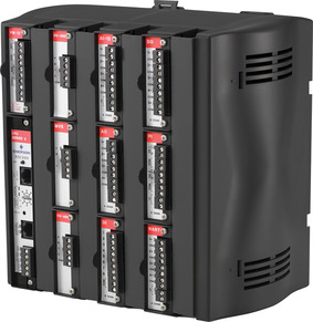 |
| Figure 5.1 Photo courtesy of Emerson Process Management. |
Ladder Logic
PLCs often use “ladder logic,” a simplistic programming language that is well suited for industrial applications. Ladder logic is based on relay-based logic and can be thought of as a set of connections between inputs (contacts) and outputs (coils). Ladder logic follows a relay function diagram, as shown in Figure 5.2. A path is traced on the left side, across “rungs” consisting of various inputs. If an input relay is “true” the path continues, and if it is “false” it does not. If the path to the right side completes (there is a complete “true” path across the ladder), the ladder is complete and the output coil will be set to “true” or “energized.” If no path can be traced, then the output remains “false,” and the relay remains “de-energized.”1
1.PLCTutor.com, Ladder logic. < http://www.plctutor.com/relay-ladder-logic.html>, October 19, 2000 (cited: November 29, 2010).
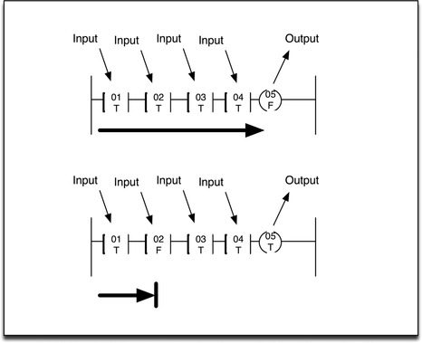
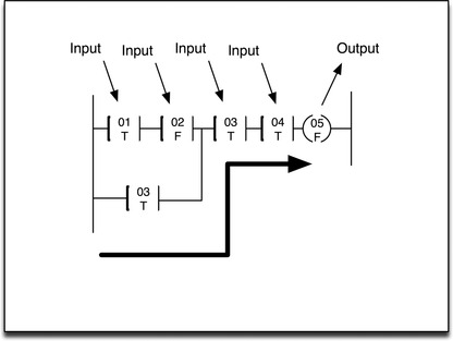
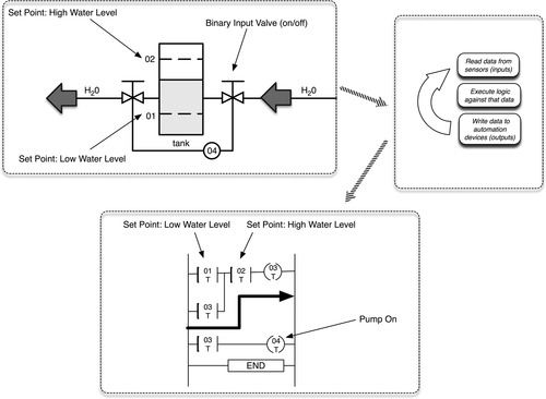
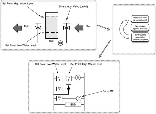
The PLC applies this ladder logic by looking at inputs from digital or analog devices such as sensors that are connected to the outside world and comparing them to set points. PLCs can use a variety of digital and analog communications methods, but typically use a fieldbus protocol such as Modbus or Profibus (see Chapter 4, “Industrial Network Protocols”). If a set point is satisfied, the input is considered “true,” and if it is not it is considered “false.” Processes defined by ladder logic can be simple or very complex. For example, an “or” condition can allow the rung to complete based on an alternate input condition, as shown in Figure 5.3.
When an output is finally reached it becomes “true,” and the PLC activates the output. This allows the PLC to automate a function (e.g., turning a pump on or off) based on set point parameters (e.g., high and low water levels within a tank). 2
2.P. Melore, PLC operations. < http://www.plcs.net/chapters/howworks4.htm>, (cited: November 29, 2010).
Ladder logic is created using a software application on a PC and then is programmed onto a PLC by connecting that PC and transferring the ladder logic code onto the PLC. This PC can be a dedicated system or it can be a function of an HMI system. Internal relays may also be used within a PLC—these relays, unlike input relays, do not use inputs from outside but can be used by the ladder logic to lock an input on (true) or off (false) depending upon other conditions of the program. Finally, PLCs can use counters and timers, allowing PLCs to act in defined cycles or pulses, as well as storage. 3
3.P. Melore, The guts inside. < http://www.plcs.net/chapters/parts3.htm>, (cited: November 29, 2010).
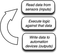
Sometimes PLCs use “Step Logic,” which differs from ladder logic in that each step is tested in isolation and progresses to the next step only upon completion, whereas in ladder logic every step is tested in each scan. Again, almost any programming language could be supported on a modern PLC. However, the end goal is ultimately to automate the relay functions common in industrial systems by checking inputs, applying logic (the program), and adjusting outputs as appropriate, 4 as shown in Figure 5.4.
4.PLCTutor.com, PLC operations. < http://www.plctutor.com/plc-operations.html>, October, 19, 2000 (cited: November 29, 2010).
HMIs
Human machine interfaces (HMIs) are used as an operator control panel to PLCs, RTUs, and in some cases directly to IEDs. HMIs replace manually activated switches, dials, and other controls with graphical representations of the control process and digital controls to influence that process. HMIs allow operators to start and stop cycles, adjust set points, and perform other functions required to adjust and interact with a control process. Because the HMI is software based, they replace physical wires and controls with software parameters, allowing them to be adapted and adjusted very easily.
HMIs are modern software applications running on modern operating systems, and as such they are capable of performing many functions. They act as a bridge between the human operator and the complex logic of one or more PLCs, allowing the operator to function on the process rather than on the underlying logic that performs the function and to control many functions across distributed and potentially complex processes from a centralized location. To accomplish this, the user interface will graphically represent the process being controlled, including sensor values and other measurements, and visible representation of output states (which motors are on, which pumps are activated, etc.).
Humans interact with the HMI through a computer console, and as such must authenticate to the HMI system using password protection. Because HMIs provide supervisory data (visual representation of a control process’s current state and values) as well as control (i.e., set point changes), user access may lock out specific functions to specific users. The security of the industrial process therefore relies heavily on access control and host security of the HMI.
The HMI, in turn, interacts with one or more PLCs and/or RTUs, typically using industrial protocols such as OLE for Process Control (OPC) or fieldbus protocols such as Modbus (see Chapter 4, “Industrial Network Protocols”).
Supervisory Workstations
A supervisory workstation collects information from assets used within a control system and presents that information for supervisory purposes. Unlike an HMI, a supervisory workstation is primarily read-only; that is, there is no control element to interact directly with the control process, only the presentation of information about that process.
Typically, a supervisory workstation will consist of either an HMI system (with read-only or supervisory access restrictions) or a Data Historian—a device specifically designed to collect a running audit trail of control system operational data. Supervisory workstations can reside within the Supervisory Control and Data Acquisition demilitarized zone (SCADA DMZ) or within the business network—up to and including Internet-facing web portals, Intranets, etc. (see “Control Processes” on page 102).
Caution
When placing a supervisory workstation or any other service outside of its intended security enclave, the overall security of that enclave is weakened. For example, by placing a SCADA supervisory console in the business network, the console can be more easily accessed by an attacker and then utilized to communicate back into the SCADA DMZ. This is covered in detail in Chapter 7, “Establishing Secure Enclaves”.
Data Historians
A Data Historian is a specialized software system that collects point values and other information from industrial devices and stores them in a purpose-built database. Most industrial asset vendors—including ABB, Arreva, Emerson, GE, Invensys, Rockwell, Siemens, and others—provide their own proprietary Data Historian systems. In addition, there are third-party industrial Data Historian vendors, such as Canary Labs (www.canarylabs.com), Modiüs (www.modius.com), and OSIsoft (www.osisoft.com), which interoperate with third-party assets and even integrate with third-party Data Historians in order to provide a common, centralized platform for data historization and analysis.
Data points that are historized and stored within a Data Historian are referred to as “tags” and can represent almost anything—the current frequency of a motor or turbine, the rate of airflow through an heating, ventilation, and air-conditioning (HVAC) system, the total volume in a mixing tank, the specific volumes of injected chemical catalysts in a tank, etc. Tags can even represent human-generated values, such as production targets and acceptable loss margins.
Because the information stored within a Data Historian is used by both industrial operations and business management, Data Historians are often replicated across an industrial network. This can represent a security risk, as a Data Historian in a less secure zone (i.e., the business network) could be used as a vector into more secure zones (i.e., the SCADA DMZ). As such, Data Historians should be isolated, secured within their own enclaves, and should be patched regularly to minimize vulnerability.
Note
The information collected by a Data Historian is stored centrally within a database. Depending upon the Data Historian used, this could be a commercial Relational Database Management System (RDBMS), specialized columnar or time-series database system, or some other proprietary data storage system. The type of database used is important for several reasons. First, the Data Historian will typically be responsible for collecting information from thousands or even millions of devices. Especially in larger networks, the capabilities of the database in terms of data collection performance can impact the Data Historian’s ability to collect operational information in real time. Second, and more importantly within the context of this book, is that commercial RDBMSs may present specific vulnerabilities to cyber attack. The Data Historian and any auxiliary system (database server, network storage, etc.) should be included in any vulnerability assessment, and care should be taken to isolate and secure these systems along with the Data Historian server.
At the time of this writing, OSIsoft holds a dominant position in the Historian market, with 65% market penetration in global industrial automated systems. 5 The OSIsoft PI System integrates with many IT and OT systems including other Data Historians, and as such is a premium target for attack. Again, applying the latest updates and patches can minimize vulnerabilities, while properly isolating and securing PI within its own enclave can minimize accessibility. For more information about the role of Data Historians within control system operations, see “Control Processes: Feedback Loops” and “Control Processes: Business Information Management” later in the chapter.
5.OSIsoft, OSIsoft company overview. < http://www.osisoft.com/company/company_overview.aspx>, 2010 (cited: November 29, 2010).
Business Information Consoles and Dashboards
Business Information Consoles are extensions of supervisor workstations designed to deliver business intelligence information to upper management. They typically consist of read-only representations of the same data obtained from HMI or Data Historian systems. In some cases, a Business Information Console is a physical console: a computer display connected to an HMI or Historian within the SCADA DMZ, but physically located elsewhere (such as an executive office or trading floor). In these cases, the physical display is remotely connected using a remote display or secure remote Keyboard Video Mouse (KVM) switching system. Business information may also be obtained by replicating HMI or Data Historian systems within the business network or by publishing exported information from these systems using an intermediary system, for example, exporting Data Historian information to a spreadsheet and then publishing that spreadsheet to a corporate information portal or intranet. Depending upon the sophistication of the Data Historian, this publishing model may be streamlined and automated. In any case, any published data should be access controlled, and any open communication path from SCADA systems to more openly accessible workstations or portals should be very carefully controlled, isolated, and monitored.
Other Assets
There are many other assets that may be connected to an industrial network other than PLCs, RTUs, HMIs, Historians, and various workstations. Devices such as printers and print servers may be connected to corporate networks, or they may connect directly to a control loop. Physical access control systems such as badge scanners and biometric readers may be used, and these devices may be networked (probably over Transmission Control Protocol/Internet Protocol [TCP/IP]).
Although this book does not attempt to cover every aspect of every device that may be present within an industrial network, it is important to recognize that every device has a potential impact to security and should be assessed if:
1. It is connected to a network of any kind (including wireless networks originating from the device itself, as with some printers).
2. It is capable of transporting data or files, such as removable media (mobile devices).
Even the most harmless seeming devices should be assessed. Check the documentation of devices to make sure that they do not have wireless capabilities, and if they do, secure or disable those features. Many commercially produced devices contain multipurpose microprocessors, which may contain radio or Wi-Fi antennae receivers or transmitters even if the device is not intended for wireless communication. This is because it is sometimes more cost-effective to use a commercial, off-the-shelf (COTS) microprocessor with unneeded capabilities; those capabilities may never be enabled by the manufacturer, but if the hardware exists it can be used as an attack vector by hackers. 6
6.J. Larson, Idaho National Laboratories, Control systems at risk: sophisticated penetration testers show how to get through the defenses, in: Proc. 2009 SANS European SCADA and Process Control Security Summit, October, 2009.
Network Architectures
As with all networks, industrial networks vary considerably. However, because many common functions within industrial systems vary widely—from automation systems, to supervisory and control systems, to business systems—there are natural demarcations within the network where these systems intersect. Table 5.1 indicates some of the major difference between these functional groups. The primary requirement of an industrial automation system is real-time operation and reliability, while the primary requirement of a business network might be high bandwidth and low operation costs. These requirements drive the use of real-time fieldbus protocols within control system processes and control loops, while business networks utilize fast, low-cost Ethernet networks and TCP/IP. SCADA systems sit between these two very different networks. In many ways, SCADA systems share the requirements of the control system itself—they need to be able to operate in real time, for example. However, they must also communicate with business systems over TCP/IP.
For this reason, a DMZ is recommended for supervisory systems. The SCADA DMZ sits between the operational and automation systems that they are supervising and controlling, and the business networks and business information systems. The DMZ is protected from both directions, using a firewall, intrusion detection and/or protection system, a data diode, or other perimeter defensive mechanism to prevent unauthorized traffic from crossing into or out of the DMZ. Logically, this creates three network areas: business, supervisory, and operations, as illustrated in Figure 5.5.
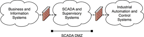
The operational and automation systems contain PLCs, RTUs, and IEDs, as well as HMI systems. The SCADA DMZ will also contain HMI systems, as well as Data Historians, MTUs (connecting to remote facilities), and Inter Control Center Protocol (ICCP) clients and servers for communicating with peer systems (see Chapter 4, “Industrial Network Protocols”). Business networks contain common computing and business systems, as well as supervisory workstations and replicated Data Historians.
Topologies Used
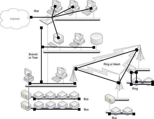
Industrial networks are typically very distributed and vary considerably in all aspects, including the link layer and network protocols used, as well as the topology. In the business networks, however, Ethernet and TCP/IP networks are ubiquitous, using a variety of star, tree, and even full-mesh topologies. The ubiquity of Ethernet and TCP/IP make it the “glue” that connects other SCADA and industrial control systems together. SCADA and industrial control system networks may utilize bus, ring, star, and tree topologies depending upon the specific type of control process that is in operation and the specific protocols that are used. For example, an automated control process to sanitize water may use a bus topology with the Modbus protocol, while another control process may use Profibus in a ring topology to control pumping or filtration systems (see Figure 5.6 for examples of topology use within and across an industrial network). The SCADA DMZ must communicate to both sides: on one side a number of industrial network protocols and on the other corporate Ethernet TCP/IP networks. As such, the SCADA DMZ will require protocol gateways to translate between the two environments (see Chapter 4, “Industrial Network Protocols”). These gateways can be standalone network devices, or they may be a built-in function of MTUs, HMIs, PLCs, or other industrial assets.
The specific topology used has little impact on the security of any particular network. More important is the boundary of a network area (which will help to determine how an attacker can migrate between systems) and the protocol(s) used within a network area (which will help to determine how a specific network area may be vulnerable). Although these areas are shown at a very high level in Figure 5.5, each network area that can be differentiated from its neighbors—ICCP interconnects versus OPC SCADA systems versus different control groups using DNP3, Modbus, etc.—can and should be isolated behind a secure periphery (see Chapter 7, “Establishing Secure Enclaves”).
Special Topology Considerations
One area that deserves special consideration is the smart grid. As mentioned in Chapter 4, “Industrial Network Protocols,” the smart grid is an extensive network providing advanced metering and communications capabilities to power distribution, and as such it is at once specific to the energy industry and yet also a concern for any other industrial network that may connect to the smart grid as a client of the energy industry.
As with all networks, the “smart grid” also varies widely by deployment, and the topologies and protocols used will vary accordingly. However, there is one primary quality that is consistent across any smart grid deployment, and that is its scale and accessibility. As a distribution system designed to deliver power ubiquitously to residences, offices, storefronts, and all aspects of urban infrastructure, even small smart grid deployments create large numbers of nodes and network interconnections, often in hundreds of thousands or even in millions. The scale of a smart grid requires the use of some mechanism to “tier” or hierarchically distribute the nodes.
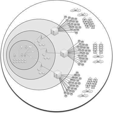
Represented in terms of an addressable attack surface, smart grids provide broad and easy access to a network that ultimately interconnects to our energy transmission and distribution infrastructure, as well as to many interconnected homes and businesses. In Figure 5.7, the attack surface is illustrated as being exponentially larger as we radiate outward from core energy generation through to the outer reaches of the smart grid.
Scalability also plays a role in the development of smart grid devices, putting significant cost pressure on the end-node devices (Smart Meters). Any device deployed at such a large-scale needs to be as efficient to build, deploy, and operate as possible. Because of the costs and complexity of providing security assurance and testing in the various supply, design, and manufacturing stages of Smart Meter development, this business driver is a real concern. As pressures force costs down, there is an increased chance that some physical or network-based vulnerability will find its way into production, and therefore into one of the most easily reachable networks ever built.
Control System Operations
All of the industrial network protocols, devices, and topologies discussed up to this point are used to create and automate some industrial operations: refining oil, manufacturing a consumer product, filtering water, generating electricity, synthesizing and combining chemicals, etc. A typical industrial operation consists of several layers of programmed logic designed to manipulate mechanical controls in order to automate the operation. Each specific function is automated by a control loop, while multiple control loops may be combined or stacked together to automate larger processes.
Control Loops
Industrial networks are made up of many specific automated processes, called control loops. The term “loop” derives from the ladder logic that is widely used in these systems: a controller device such as a PLC is programmed with specific logic; the PLC then cycles through its various inputs, applying the logic to adjust outputs or controls, in order to perform a specific function. This cycle or “loop” automates that function.
In a closed loop, the output of the process affects the inputs, fully automating the process. For example, a water heater is programmed to heat water to 90°C. An electric heater coil is then engaged to heat the water, and the water temperature is measured and fed back into the process; when 90°C is reached, the heater will turn off inputs from outside of the specific process. In an open loop, the output of the process does not affect the inputs, such as when the coil of a water heater is manually engaged, independent of the current water temperature. In other words, closed loops provide automated control whereas open loops provide manual control.
Control loops can be very simple, checking a single input, as illustrated in Figure 5.8 and Figure 5.9. For example, a simple loop in an automated lighting process might check a single input (e.g., a light sensor to measure ambient light) and adjust a single output (e.g., the dimmer switch on a lamp). Very complex loops might use multiple inputs (e.g., pressure, volume, flow, and temperature sensors) and adjust multiple outputs (e.g., valves, pumps, heaters) to perform a function that is inherently more complex—in this case, maintaining a constant pressure in a dynamic fluid system.
Multiple control loops may be required to perform even more complex control processes. They may be controlled by a central HMI, or they may themselves be part of a larger control loop, acting as inputs or outputs into another level of logic, controlled by a master or central PLC.
Control Processes
A “control process” is a general term used to define larger automated processes within an industrial operation. Many control processes may be required to manufacture a product or to generate electricity, and each control process may consist of one or many control loops. For example, one process might be to inject an ingredient into a mixer, and that process may consist of a control loop that opens a valve in response to volume measurements within the mixer, temperature, and other conditions. Several such processes can automate the correct timing and combination of several ingredients, which in turn complete a larger process (to make a batter). The mixed batter might then be transported to other entirely separate control processes for baking, packaging, and labeling.
Each process is typically managed using an HMI, which is used to interact with that process. Typically, an HMI will provide relevant readings from one or more control loops, requiring communication to all daughter systems, typically PLCs or RTUs. Some HMIs may include readouts of sensors and other feedback mechanisms, as well as the activity of the PLCs, while others may issue direct control operations and provide controls to adjust the set points of the ongoing control process.
Again, an HMI may control a process consisting of many control loops; therefore, the HMI’s network connectivity is typically heterogeneous: connecting over routable protocols (TCP/IP) as well as specialized SCADA and fieldbus protocols and other industrial network protocols to the various PLCs and RTUs that make up the individual loops. Because of this, HMIs are a common attack vector between the routable SCADA and business networks.
Feedback Loops
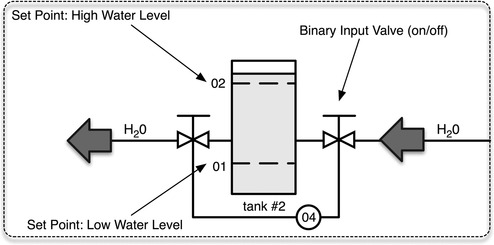
Every automated process relies on some degree of feedback both within a control loop and between a control loop or process and a human operator. Feedback is generally provided directly from the HMI used to control a specific process, as seen in Figure 5.10. Feedback may also be centralized across multiple processes, through the collection, analysis, and display of information from many systems. For example, a refinery may have several crude oil tanks, each used in a replicated control process. Information from each process can be collected and analyzed together to determine production averages, overages, and variations.
The centralized information management of an industrial control system is typically performed by one or more Data Historian systems. The process of removing data from the real-time environment of an industrial automation process and storing it over time is called “historizing” the data. Once historized, the information can be heavily analyzed, either directly from within the Data Historian or by using an external analysis tool such as a spreadsheet.
Specific control system elements may use their own Data Historian system to historize data locally. For example, an ABB 800xA control system may use the 800xA Information Management Historian, while an Emerson Ovation control system may use the Ovation Process Historian. The need for a common Data Historian that historizes all data across systems derives from the heterogeneous nature of many industrial operations, where different processes may utilize assets manufactured by different vendors, yet all processes need to be evaluated holistically in order to manage and fine-tune overall operations. In addition, there may be value in collecting information from other devices and systems within the industrial network, such as IT systems, HVAC systems, and Physical Security and Access Control systems. The shift from process-specific data historization to operation-wide business intelligence has led to the development of specialized features and functionality within Data Historians.
Business Information Management
Operational monitoring and analysis provides valuable information that can be used by business managers to fine-tune operations, improve efficiencies, minimize costs, and maximize profits. As such, there is a need for replication of the operational process data into the business network.
Supervisory data can be accessed using an HMI or a Data Historian, each of which presents its own security challenges. HMIs provide supervisory and control capabilities, meaning that an HMI user with the correct privileges can adjust parameters of control process (see “Control Process Management” on page 106). By placing an HMI outside of the SCADA DMZ, any firewalls, IDS/IPS, and other security monitoring devices that are in place will need to be configured to allow the communication of the HMI into and out of the SCADA DMZ, effectively reducing the strength of the security perimeter between the SCADA and business networks to user authentication only. That is, if a user account is compromised on the outside HMI system, it can be used to directly manipulate control process(es), without further validation from perimeter security devices.
The use of a Data Historian for business intelligence management presents a similar concern: the security perimeter must be configured to allow the communication between the Data Historian in the Business network and the various systems within the SCADA DMZ that need to be monitored. Unlike an HMI, a replicated Data Historian does not explicitly allow control of the process. Instead, the Data Historian provides a visual dashboard that can be configured to mimic the informational qualities and graphical representation of an HMI so that information about a process can be viewed in a familiar format.
Tip
Because the replication of Data Historian systems into the business network is for information purposes only, these systems can be effectively connected to the SCADA DMZ using a unidirectional gateway or data diode (see Chapter 7, “Establishing Secure Enclaves”). This preserves the security perimeter between business and supervisory networks, by allowing only outbound data communications. However, data outbound (from the SCADA DMZ to the business network) should still be secured using one or more security devices such as a firewall, IDS/IPS, or application monitor.
Data is collected by a Data Historian through a variety of methods including direct communication via industrial network protocols such as Modbus, Profibus, DNP3, and OPC (see Chapter 4, “Industrial Network Protocols”); via direct insertions in the Data Historian’s database using Object Linking and Embedding Database (OLEDB), Open Database Connectivity (ODBC), Java Database Connectivity (JDBC), etc.; or using standard data exchange protocols such as the Simple Network Management Protocol (SNMP) and Syslog. Most Data Historians support multiple methods of data collection to support a variety of industrial applications. Once the information has been collected, it is stored within a database schema along with relevant metadata that helps to apply additional context to the data, such as batch numbers, shifts, or virtually anything (depending upon the Data Historian’s available features and functionality).
Data Historian systems also provide access to historized data, typically through the same supported interfaces, with the possible addition of more ubiquitous protocols such as HTTP. Historized data can therefore be retrieved via direct SQL queries, via HTTP requests, via direct fieldbus protocol reads, or via other means. The data itself could be presented in almost any format, including binary files, XML, etc.
Historized data may be accessed directly via the Data Historian’s operator console or could be integrated at almost any level into supplementary Business Intelligence Management systems. In some cases, the Data Historian may also be integrated with Security Information and Event Management systems (SIEMs), Network Management Systems (NMSs), and other network and/or security monitoring systems.
Control Process Management
A control process is initially established through the programming of PLCs to build a control loop. In a fully automated loop, the process is controlled entirely through the comparison of established set points against various inputs. In a water heater, a set point might be used to establish the high-temperature range of 90°C, and an input would take temperature measurements from a sensor within the water heater tank. The PLC’s logic would then compare the input to the set point to determine whether the condition has been met (it is “true”) or not (it is “false”), in this example disengaging or engaging the heater element, respectively.
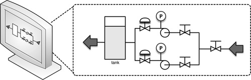
When an operator manages a control process, he or she uses real-time information about the state of the process from an HMI to determine whether manual intervention is required (open loop) or adjustments to established set points are required (closed loop). The HMI facilitates both, by providing software controls to adjust the various set points of a control loop while also (typically) providing controls to directly affect the loop.
In the case of set point adjustments, the HMI software is used to write new set points in the programmable logic of the loop controller (the PLC or RTU). This might translate to function code 6 (“Write Single Register”) in a Modbus system, although the specific protocol function is typically hidden from the operator; the HMI translates the function into human-readable controls presented within a graphical user interface (GUI), as represented in Figure 5.11.
In contrast, the HMI could also be used to override a specific process and force an output, for example, using function code 5 (“Write Single Coil”) to write a single output to either the on (“true”) or the off (“false”) state. 7 Again, the specific function code used to write the output state is hidden from the operator.
7.The Modbus Organization, Modbus application protocol specification V1.1b, Modbus Organization, Inc. Hopkinton, MA, December 2006.
Note
The specific function codes used vary among industrial network protocols, and many protocols support vendor-proprietary codes. Although these protocols are discussed in Chapter 4, “Industrial Network Protocols,” this book does not document protocol function codes. Refer to your user documentation for supported function codes.
This represents a significant security concern. If an attacker is able to successfully compromise the HMI, fully automated systems can be permanently altered through the manipulation of set points. For example, by changing the high-temperature set point to 100°C, the water in a water heater tank could boil, potentially increasing the pressure enough to rupture the tank. Direct changes to a process loop’s output controls can also be forced by an attacker. In this example, the water heater’s coil could be engaged manually by the attacker. In the case of Stuxnet, malware inserted into a PLC listened to a Profibus for an indication of a specific frequency converter operating at a specific frequency range. If those conditions were found, multiple commands are sent to the controller, alternating the operating frequency and essentially sabotaging the process. 8
8.E. Chien, Symantec. Stuxnet: a breakthrough. < http://www.symantec.com/connect/blogs/stuxnet-breakthrough>, November, 2010 (cited: November 16, 2010).
Smart Grid Operations
Smart grid operations consist of several overlapping functions, intercommunicating and interacting with each other. These include Customer Information systems, Billing Systems, Demand Response systems, Meter Data Management Systems, and Distribution management systems. These systems communicate with an Advanced Metering Infrastructure (AMI) Headend, which in turn feeds local distribution and metering, as shown in Figure 5.12. The AMI Headend will typically connect to large numbers of Smart Meters, serving a neighborhood or urban district, which in turn connect to home or business networks.
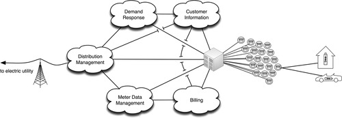
The Customer Information system supports the business relationship between the utility and the customer, and may connect to both the customer premise (via customer service portals) as well as the utility back-end systems (e.g., corporate CRM). Meter Data Management systems store data, including usage statistics, energy generation fed back into the grid, Smart Meter device logs, and other meter information, from the Smart Meter. Demand Response systems connect to Distribution Management systems and Customer Information systems as well as the AMI Headend to manage system load based on consumer demand and other factors. 9
9.G. Locke, US Department of Commerce and Patrick D. Gallagher, National Institute of Standards and Technology, Smart Grid Cyber Security Strategy and Recommendations, Draft NISTIR 7628, NIST Computer Security Resource Center, Gaithersburg, MD, February 2010.
Smart grid deployments consist of multiple AMI Headends, which may interconnect via a mesh network (where all Headends connect to all other Headends) or hierarchical network (where multiple Headends aggregate back to a common Headend), and may support hundreds of thousands or even millions of meters. All of this represents a very large and distributed network of intelligent end nodes (Smart Meters) that ultimately connects back to energy transmission and distribution. 10 The benefits of this allow for intelligent command and control of energy usage, distribution, and billing. 11 The disadvantage of such a system is that the same end-to-end command and control pathways could be exploited to attack one, any, or all of the connected systems. Some specific threats concerning smart grids include
10.UCA® International Users Group, AMI-SEC Task Force, AMI system security requirements, UCA, Raleigh, NC, Dec 17, 2008.
11.Ibid.
• Bill Manipulation/Energy Theft—An attack initiated by an energy consumer with the goal of manipulating billing information to obtain free energy. 12
12.Raymond C. Parks, SANDIA Report SAND2007-7327, Advanced Metering Infrastructure Security Considerations, Sandia National Laboratories, Albuquerque, New Mexico and Livermore, California, November 2007.
• Unauthorized Access from Customer End Point—Use of an intelligent AMI end node (a Smart Meter or other connected device) to gain unauthorized access to the AMI communications network. 13
13.Ibid.
• Interference with Utility Telecommunications—Use of unauthorized access to exploit AMI system interconnections in order to penetrate the bulk electric generation, transmission, and distribution system. 14
14.Ibid.
• Mass Load Manipulation—The use of mass command and control to manipulate bulk power use, with the goal of adversely affecting the bulk electric grid. 15
15.Ibid.
• Denial of Service—Using intelligent nodes to communicate to other nodes in a storm condition, with the goal of saturating communications channels and preventing the AMI from functioning as designed.
The AMI Headend is a prime target due to its central position in the smart grid: all end nodes, business systems, operational systems, and distributed control systems connect to (or through) the Headend. Compromise of the AMI Headend would provide a vector of attack to many systems. Similarly, if any other connected system were compromised the next hop would likely be to the Headend. Therefore, all inbound and outbound communications at the Headend should be carefully monitored and controlled (see Chapter 9, “Monitoring Enclaves”).
Summary
Industrial networks operate differently from enterprise networks and use specialized devices including IEDs, RTUs and/or PLCs, HMIs, Control System Assets, Supervisory Management Workstations, Data Historians, and Business Information Consoles or Dashboards. These devices utilize specialized protocols to provide the automation of control loops, which in turn make up larger industrial control processes. These automated control processes are managed and supervised by operators and managers within both SCADA and business network areas, which requires the sharing of information between two disparate systems with different security requirements.
This is exemplified in the smart grid, which shares information between multiple disparate systems, again across different networks each of which has its own security requirements. Unlike traditional industrial network systems, however, the smart grid represents a massive network with potentially millions of intelligent nodes, all of which communicate back to the energy provider, and possibly to other homes, businesses, or industrial facilities consuming power from the grid.
By understanding the assets, architectures, topologies, processes, and operations of industrial systems and smart grids, it is possible to examine them and perform a security assessment in order to identify prevalent attack vectors, or paths of entry that an attacker could use to exploit the industrial network.
..................Content has been hidden....................
You can't read the all page of ebook, please click here login for view all page.