
Chapter 8
Electric Candle
Ingredients
- 1 Arduino Uno
- 1 Arduino USB cable
- 1 breadboard
- 1 push button
- 1 10k-ohm (10kΩ) resistor, which has a brown-black-orange stripe pattern
- 1 LED
- 10 jumper wires
- Your computer
Special items
Optional Items
- 1 Arduino power supply
How might we make a LED candle you can actually blow out? That was a question my daughter and I had one evening, so we got online and started exploring different ways to sense wind. Along the way, we discovered a pretty nifty sensor that does exactly what we needed. That sensor is the center of this project.
Concepts: Sensing Air Movement and Wind
Weather stations use sets of spinning cups, called anemometers, to measure wind. Another way to detect air movement might be to hang two strips of tinfoil next to each other and detect when they touch, completing an electrical circuit—though that might also detect a curious cat.
There’s another method, which works on the same principle you use when your pizza slice is too hot to eat and you blow on it to cool it down.
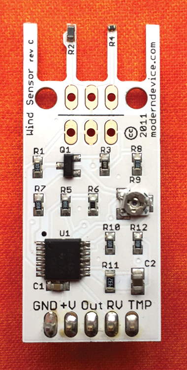
Figure 8-1: The Modern Device wind sensor
In the same way, a wire warmed up by a little electricity will cool when air blows across it—and it’s possible to measure that temperature change to sense the wind!
These are called “hot-wire” wind detectors, and there’s one that plays nicely with an Arduino.
Almost all of the ingredients you’ll need come in typical Arduino starter kits, with the notable exception of the wind sensor. For this project, you’ll need one. You can search the Internet for “Modern Device Wind Sensor” or get the link at http://keefe.cc/electric-candle.
Steps
The wind sensor requires some assembly. You need to solder the row of pins to the sensor so you can then stick them into the breadboard. This little row of pins is known as the “header.”
Wait, Soldering? Scary!
Not at all!
Soldering is not difficult, but you do need a soldering iron, some solder, and a little lesson.
If you don’t have a soldering iron or solder, you can get them at a local hardware or hobby store, and of course from an online seller. Links to some of those are also at http://keefe.cc/electric-candle.
Learning to solder is empowering, awesome, and easy. The best tutorial I know of is at Adafruit. Here’s an easy link to it: http://keefe.cc/soldering.
This project is a great time to learn, because you need to solder just five spots: the five pins that make the “header” to stick into the breadboard. (The header pins come with the sensor board.)
The hardest part of soldering is holding everything together while you actually apply the solder to the pins. But in this case, your breadboard can be your assistant.
Just push the long ends of the header pins into the breadboard and place the holes at the end of the wind sensor onto the short ends. To keep the board level, place a coin between the breadboard and the other end of the sensor board.
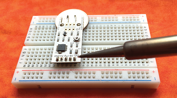
Figure 8-2: To free your hands for soldering, push the long ends of the header pins into the breadboard and place the five holes of the wind sensor on top of the short ends. Use a coin to keep the wind sensor level.
Then solder away, making sure none of the solder from one pin touches solder from another pin.
Once you have the header attached, you’re good to go.
Wire Up the Parts
Here’s the wiring diagram for this project:
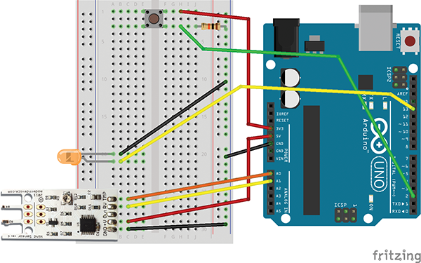
Figure 8-3: The wiring diagram for the "Electric Candle" project, with the Modern Device wind sensor on the breadboard at the bottom left
- Insert the button at the top of the breadboard so it straddles the center canal of the breadboard and two of its legs are in Row 1.
- Grab the resistor, and put one of its legs into the breadboard’s Column j at Row 3. Take special note here: This leg should be in the same row as a leg of the button. But some buttons are different sizes, and if yours has a leg in a different row, put this resistor leg in that row instead. The resistor leg should be in the same row as the button leg (but also not in Row 1).
- Put the other leg of the resistor in any hole along the blue “–” rail.
- Grab the LED and insert its shorter leg into the breadboard’s Column a at Row 20.
- Insert the LED’s longer leg one hole below, in Column a at Row 21.
- At the point where the LED legs meet the breadboard, carefully bend the LED at a right angle so it’s basically “lying down” on the breadboard.
- Insert the 5 pins of the wind sensor into the bottom five rows of the a column on the breadboard, so they’re in rows 26 through 30. The rest of the wind sensor should extend off of the left side of the board, and the sensor’s
GNDpin should be in Column a at Row 30.
Things should now look like this:
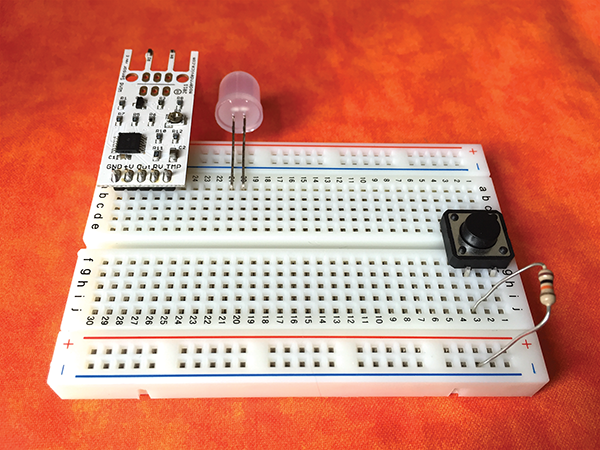
Figure 8-4: The parts for the "Electric Candle" project, on the breadboard and ready for jumper wires
Time for the jumper wires! Each step below is for one jumper wire, with the connections for both ends. The colors really don’t matter, but I’ll mention them as they match the illustration.
- Insert one end of a (red) jumper wire into the Arduino’s
3.3Vpin, and the other end into the breadboard’s Column h at Row 1. - Insert one end of a (green) jumper wire into the Arduino’s
2pin along the “Digital” row, and the other end into the breadboard’s Column h at Row 3. Note that this end should share a row with one of the button legs and one of the resistor legs. If your button leg is in a different row, use that row instead. - Insert one end of a (black) jumper wire into one of the Arduino’s
GNDpins, and the other end into any hole along the breadboard’s blue “–” rail on the right—the same rail as one leg of the resistor. This will be our “ground rail,” which will provide ground to all of the items on the breadboard. - Insert one end of (another black) jumper wire into the same blue “–” rail on the breadboard, and the other end into the breadboard’s Column b at Row 20. This is the same row as the short leg of the LED, providing ground, or the negative “–” side of the circuit, to the LED.
- Insert one end of a (yellow) jumper wire into the Arduino’s Pin
13, and the other end in the breadboard’s Column b at Row 21—the same row as the longer leg of the LED. - Insert one end of a (red) jumper wire into the Arduino’s
5Vpin, and the other end into the breadboard’s Column c at Row 29. Notice that that’s the same row as the sensor’s+Vpin. This wire provides the power to the sensor. - Insert one end of an (orange) jumper wire into the Arduino’s Pin
A0, and the other end in the breadboard’s Column c at row 26. This is the same row as the sensor’sTMPpin. - Insert one end of a (yellow) jumper wire into the Arduino’s Pin
A1, and the other end into the breadboard’s Column c at Row 27. This shares a row with the sensor’sRVpin. - Finally, insert one end of a (black) jumper wire into the breadboard’s Column c at Row 30, and the other end into any hole in the blue “–” rail on the right side of the breadboard—our “ground” rail.
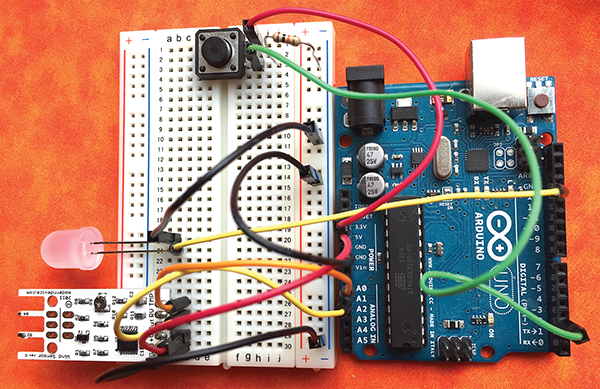
Figure 8-5: A photo of the "Electric Candle" project, assembled
Load Up the Code
Get the project code in one of these now-familiar three ways:
From the Web
- Use a web browser to visit http://keefe.cc/electric-candle.
- Follow the same instructions as in previous chapters.
From the Bundle
Don’t have the bundle yet? Check out the instructions in Appendix B. Then . . .
- Find your
family-projects-sketches-masterfolder, and double-click it to open it. - Click on the
electric_candlefolder. - Inside, you’ll see
electric_candle.ino. It’ll have a blue Arduino icon. - To use it, just double-click the file name and it should open in your Arduino software.
From the Back of This Book
If you’re reading this book on your computer, you may be able to copy and paste the code from the back of the book into your Arduino software. If that’s the case:
- On your computer, start up your Arduino software and start a new sketch from the menu bar: File → New.
- Delete what’s in the window that pops up.
- Go to Appendix B and highlight the entire code block for this chapter.
- Copy the code using Edit → Copy from the menu.
- Switch back to the Arduino software and click into the blank window.
- Paste the code you copied from Appendix B using Edit → Paste from the menu.
No matter how you got the project code into your Arduino software, be sure to save your work, using File → Save.
Make It Go
With the LED glowing, give a good puff across the top of the sensor. The light should go out! Press the button on the breadboard to relight it.
To free your candle from the computer’s tether, you can plug an optional power adapter into your Arduino.
You could also power the project with a 9-volt battery. There are some battery holders that have an Arduino adapter and a little switch. That’s important because even when the candle is out, your Arduino is still running. So power it down completely with the switch (or by unplugging the battery) or you’ll run out of juice.
Fixes
The code should work to detect a good puff. If you want to make it more or less sensitive, adjust the wind speed that triggers the dousing by changing the number in the following line from 6 to something else:
if (WindSpeed_MPH > 6) {What's Going On?
As air moves across the sensor’s “hot wire” (it’s not that hot), the wire cools and its conductivity changes. The other electronics on the board detect this change and turns it into values the Arduino can read.
When the values hit a threshold, we douse the light . . . and wait for someone to push the button to relight it.
Code Corner
You're a Star
There is some serious math going on in the code for this project. You don’t need to know all of what’s happening, of course, but I thought it would be a good time to point out some basic math symbols.
You probably gather that + is used for addition and - is used for subtraction.
But what about *? That’s multiplication. So 2 * 3 equals 6.
And / is for division. Which means 6 / 3 is 2.
In this code, there’s even a pow. That’s not comic-book slang for a punch; it’s “power,” as in 10 to the power of 2. You might know that as 102. In Arduino, that’s written pow(10, 2). Either way, it’s 100!
Fun Functions
If you take a peek at the code for this project, you’ll see our old friends void setup() and void loop(). But scroll down a bit and you’ll see they’re joined by a couple of new sections: void douseCandle() and void lightCandle(). What’s going on there?
These are two functions I’ve created to perform a specific task in the code. Basically, I’ve added two commands to the existing Arduino vocabulary, joining existing commands such as analogRead() and digitalWrite().
Up in the void loop() section, I “call” these functions in a couple of different spots. One of them looks like this:
if (WindSpeed_MPH > 6) {
  douseCandle();
}
When the program sees douseCandle(), it goes and looks for the function I’ve made, which is written like this . . .
void douseCandle() {

  // turn LED off
  digitalWrite(led, LOW);

}
When the function is called, the program runs the code between the function’s brackets { }—which sets the LED pin to “LOW.”
Functions are super useful. For one, they let you run the same block of code in many different spots. You can create a function for that code, and then just call the function whenever you need it.
That way, you don’t repeat yourself—which is something coders try to abide by. They even have a name for it: “DRY” code (for Don’t Repeat Yourself).
Taking It Further
We’re interested in whether there is any significant air movement across the sensor. But this little device can actually provide good data on how fast that air is moving—an actual wind speed detector.
To be accurate, though, the sensor needs its own source of power, separate from the Arduino. That’s because the power running through the Arduino can fluctuate slightly, and that will affect the precise measurements of the sensor. Links to more information on how to wire up a separate power supply are at http://keefe.cc/electric-candle.