
Chapter 5
Ice, Ice Blinky
Ingredients
- 1 Arduino Uno
- 1 Arduino USB cable
- 1 breadboard
- A piece of ice
- Your computer
Special Items
- 1 thermistor (model TMP36)
Thermometers are important. They help you decide whether you need a jacket today, and they let you know if the aquarium water is the right temperature for your tropical fish. Thermometers connected to tiny computers can make decisions based on temperature, doing things like turning on lights at a certain temperature, sounding alarms when things are too hot or too cold, and keeping track of temperatures over time.
Let’s get started by making an LED react to cold water.
Concepts: Temperature Sensing
“Thermistors”—you can think of the word as a mashup of “thermal” and “resistor”—are simple devices that change electrical resistance with the temperature. And as we’ve seen, Arduinos are excellent at detecting changes in resistance. So a thermistor and an Arduino make a very effective temperature sensor.
Almost all Arduino starter kits include a thermistor, and when they do it’s usually the TMP36. This is a simple, black part with three legs and one flat side. If you don’t have one, they’re quite cheap. Find links to buying one at http://keefe.cc/ice-blinky.
Steps
Wire Up the Parts
Here’s how to wire up this project:
- Put the longer LED leg into Pin
13on the Arduino. - Put the shorter LED leg into the
GNDpin on the Arduino, right next door. - Notice that the thermistor has three legs, and also that it has a rounded side and a flat side.

Figure 5-1: The position of the temperature sensor, with the flat side facing at the printed numbers along Column a
- Insert the three legs of the thermistor into in the breadboard’s holes along Column a at rows 1, 2, and 3 with the flat side facing the breadboard’s printed row numbers. The rounded side should be facing the other direction, toward the breadboard’s center canal. You’ll have to separate the legs a little to get them into each of the holes.
- Connect one end of a jumper wire (preferably a red one) to the Arduino’s Pin
5V, and connect the other end to the breadboard’s Row 1—let’s use Column e. - Connect one end of another jumper wire (any color; I used yellow) to the Arduino’s Pin
A0, and the other to the breadboard’s Row 2 at Column e. Notice that we’re staying on the same side of the breadboard’s central canal. - Connect one end of a (preferably black) jumper wire to any of Arduino’s
GNDpins, and the other end of the wire to the breadboard’s Row 3 at Column e. - Double-check that all of your connections are on the same side of the breadboard’s central canal.
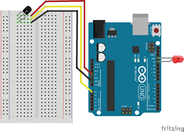
Figure 5-2: Wiring the temperature sensor to the Arduino. The flat side of the thermistor is pointing toward the left of this image, and the rounded side toward the breadboard’s central canal.
Load Up the Code
Just as in “A Dark-Detecting Light,” we’ll use the example code that comes with your Arduino software. So with the Arduino software running, go to: File → Examples → 03.Analog → AnalogInput.
Make It Go
Upload the code to your Arduino by pressing the arrow button at the top of the blue window or using Sketch → Upload. The LED should start blinking. (If it doesn’t, check the “Fixes” section below.)
Place a piece of ice on a dish next to the breadboard, carefully pick up the breadboard, and touch the thermistor to the ice. Watch the LED closely as you do. Can you see the flashing speed up?
Now pinch the thermistor between your fingers hold it tightly. Watch the blinking slow down as your body heat warms up the thermistor, causing the resistance to change in the other direction.
You’ve made a temperature sensor!
If you’re having trouble seeing the flashing rate change, we can make a little adjustment to make it more pronounced. Look at the code and find this line:
sensorValue = analogRead(sensorPin);Make one small change by adding *3 just to the left of the semicolon, like this:
sensorValue = analogRead(sensorPin)*3;This will triple the sensor readings, making the warmer (higher) numbers bigger—and making the flashing change more noticeable.
Fixes
If your LED isn’t lighting, be sure the correct leg is in the correct hole—remember, the longer leg goes into Pin 13.
If the LED is flashing but the speed doesn’t change much, first be sure the wires are all connected correctly. Even if nothing is sensed, this circuit will flash the LED, but the rate of flashing won’t change.
If the LED still isn’t responding much, try swapping out the regular resistor for a value that’s smaller. Try 10Ω instead. The base blink rate is tied to this resistor’s value.
What’s Going On?
Stick with me here, because how it works is kind of cool. (Ha.)
- The ice cools the thermistor.
- As the thermistor gets colder, it doesn’t conduct electricity as well. (Another way to say that is that its resistance increases.)
- The Arduino senses how much electricity arrives back at the Arduino and gives it a number. That’s the sensor value. (Technically, the sensor value is related to voltage.)
- With less electricity making it through the thermistor, the sensor value becomes a smaller number.
- That sensor value is used in the code as the number of milliseconds the program should wait between turning the LED on and turning it off (and then on again).
- When the sensor value gets smaller the wait between on and off gets smaller, too.
- If the delay between on and off (and on again) is smaller, the LED blinks faster.
Taking It Further
Seeing the Sensor Reading
We can print the sensor reading into the Serial Monitor by adding two lines to our program. The first one is Serial.begin(9600); and it goes here:
void setup() {
  // declare the ledPin as an OUTPUT:
  pinMode(ledPin, OUTPUT);
  Serial.begin(9600);  // < - - Add this line
}
The second is Serial.println(sensorValue); and it goes within the curly brackets in the void loop() section, like this:
void loop() {
  // read the value from the sensor:
  sensorValue = analogRead(sensorPin);
  // turn the ledPin on
  digitalWrite(ledPin, HIGH);
  // stop the program for <sensorValue> milliseconds:
  delay(sensorValue);
  // turn the ledPin off:
  digitalWrite(ledPin, LOW);
  Serial.println(sensorValue); // < - - New line is here
  // stop the program for for <sensorValue> milliseconds:
  delay(sensorValue);
}
Type the lines exactly as they appear, being mindful of the capital letters (case matters) and the end-of-line semicolons. Or copy it from http://keefe.cc/ice-blinky.
Upload the code to your Arduino by pressing the arrow button at the top of the blue window or using Sketch → Upload.
Then open the Serial Monitor using Tools → Serial Monitor and watch the numbers change when you touch the sensor to the ice or pinch it between your fingers. You’ll probably notice that the numbers here are not temperature readings. We can fix that.
But What’s the Temperature?
If you’re using a temperature sensor, a flashing light may be fun, but you probably want to know the actual temperature! I’ve provided a little code to do just that.
Start a new sketch using File → New, delete what’s there, and replace it with the little sketch below. It’s short enough that you could actually type it in, but you could also copy-and-paste it from http://keefe.cc/ice-blinky.
#define SENSORPIN 0
float sensor_value;
float voltage;
float tempC;
float tempF;
void setup() {
  // Start the Serial Monitor stream
  Serial.begin(9600);
  pinMode(13, OUTPUT);
}
void loop() {
  sensor_value = analogRead(SENSORPIN);
  Serial.print("Sensor Value: ");
  Serial.println(sensor_value);

  voltage = sensor_value * 5000 / 1024;
  Serial.print("Voltage (millivolts): ");
  Serial.println(voltage);

  tempC = (voltage-500) / 10;
  Serial.print("Degrees Celsius: ");
  Serial.println(tempC);
  tempF = (tempC * 9/5) + 32;
  Serial.print("Degrees Fahrenheit: ");
  Serial.println(tempF);
  Serial.println();

  delay(5000);
}
Upload this new code to your Arduino by pressing the arrow button at the top of the blue window or using Sketch → Upload.
Then open the Serial Monitor again using Tools → Serial Monitor and watch the numbers change. This time, the sensor readings are actual temperature values!
A More Useful LED
Now that we know the temperature, we can make the LED actually useful by adding some “if-then” code. Let’s say that if the temperature is above 80 Fahrenheit, then light the LED.
To do that, simply type the following lines of code immediately above the delay(5000) line:
if (tempF > 80) {
  digitalWrite(13, HIGH);
} else {
  digitalWrite(13, LOW);
}
If you still have your LED in the Arduino Pin 13, you’re all set. It will glow whenever the temperature at the thermistor climbs over 80. Tinker with the “80” number to make it your own. If you prefer to use the Celsius value instead, replace tempF with tempC.
Code Corner
In and Out
A nifty feature of the Arduino is that all of the digital pins—those numbered 0 through 13 along one side—can send power and sense power. But an individual pin can’t do both at the same time.
That’s why at the beginning of this sketch, we declare the ledPin (which represents Pin 13) as an output. Like this:
pinMode(ledPin, OUTPUT);In this case, we want to send power out to the LED. Later, when we use a digital pin to detect power coming in to the Arduino, we’ll set the pin we want to use as an “input.”
Float Along with Me
If you checked out the “Code Corner” from earlier chapters, you know a little bit about variables—words that can represent other values. You learned that you could make a variable represent an integer number, such as 1, 2, 13, and 0, by putting int in front of the variable name. Like so:
int sensorValue = 0;Take a peek at the code in “But What’s the Temperature?” above (even if you didn’t actually use that code). Near the top, you’ll see something curious. Instead of int, you’ll see float.
float sensor_value;
float voltage;
float tempC;
float tempF;
The word float refers to numbers with decimal points like 1.5 or 200.333. These are “floating point” numbers, hence the float designation.
Variables with decimals require more space in the Arduino’s tiny brain, and here the code is essentially saying “Hey Arduino, save some space for these four decimal numbers we’ll call sensor_value, voltage, tempC, and tempF. We’re not going to assign them now, but we’ll be using them later.”
Constant and Reliable
In that same code, you’ll see another curious addition at the top:
#define SENSORPIN 0The word “SENSORPIN” is being assigned to 0, much like we did with int sensorValue = 0;. But in this case, it’s not allowed to change. It must always stay as 0. So it’s not variable; it’s a constant.
Why not just make it a variable? Because constants take even less of Arduino’s brain power than variables do. Making “SENSORPIN” a constant is more efficient, which can become important when programs start getting complex enough to push the limits of the Arduino’s little brain.