
Chapter 9
Invisible Ruler
Ingredients
- 1 Arduino
- 1 Arduino USB cable
- 1 breadboard
- 3 jumper cables
- Your computer
Special parts
- 1 Ping sensor
Optional parts
- 1 LED
Maybe you know how bats “see” with sound: emitting high-pitched clicks and listening for how those sounds bounce off things. It’s called “echolocation” because the bats literally locate things using echoes. We can make an Arduino do the same thing!
Concepts: Distance Sensing
Detecting objects around us is key to navigating our world, and can be important for smart objects, too. Is the cat nearby? Am I about to bump into a wall?
To give our Arduino “eyes,” we’ll use a Ping sensor, which, just like a bat, emits high-pitched sounds and listens for them to return. By timing how long it takes the sound to make that super-quick round-trip journey, we can sense when an object is near the sensor and measure how far away it is.
As an added bonus, the Ping sensor looks like two little eyes—which can be great if you are building a robot.
The key part here is, of course, the Ping sensor. A quick Internet search will lead you to one, or you can find links at http://keefe.cc/invisible-ruler.
Steps
Wire Up the Parts
The pins on the Ping sensor are set up in a very common pattern for sensor parts:
- One pin for power, or positive “+” side of the circuit. On the Ping, it’s labeled
5Vfor 5 volts of power. - One pin for the “ground,” or negative “–” side of the circuit, marked
GNDon the Ping. - One pin for the data, providing some measure of what the sensor is sensing. On the Ping, that pin is labeled
SIGfor “signal.”

Figure 9-1: The pins on the Parallax Ping distance sensor
Wiring up this project is pretty straightforward:
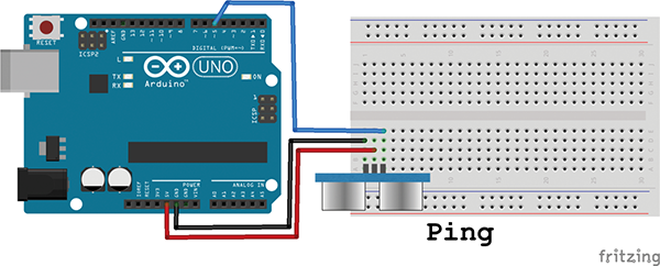
Figure 9-2: The wiring diagram for the “Invisible Ruler” project, using a Ping distance sensor. The pins on the Ping are in rows 1 through 3 on the breadboard.
- Push the Ping sensor pins into the breadboard so that the pins fit into rows 1 through 3, with the Ping’s
GNDpin fitting into breadboard Row 1 and the Ping’sSIGpin fitting into breadboard Row 3. - Insert a (preferably black) jumper wire into breadboard Row 1, the same row as the Ping’s
GNDpin. Be sure the Ping and the jumper wire are on the same side of the canal down the middle of the breadboard. - Connect the other end of this (black) jumper wire to one of the Arduino’s
GNDpins. - Insert a (preferably red) jumper wire into breadboard Row 2, the same row as the Ping’s
5Vpin. Again, be sure to stay on the same side of the center canal. - Connect the other end of this (red) jumper wire to the Arduino’s
5Vpin. - Insert one end of a third jumper wire (any color!) into breadboard Row 3, the same row as the Ping’s
SIGpin. Same rule about the canal. - Connect the other end of this third jumper wire to Arduino Pin 7.
That’s it!
Load Up the Code
Pick your favorite way to get the code:
From the Web
- Use a web browser to visit http://keefe.cc/invisible-ruler.
- Follow the same instructions as in previous chapters.
From the Bundle
Once you get your bundle . . .
- Find your
family-projects-sketches-masterfolder, and double-click it to open it. - Click on the
invisible_rulerfolder. - Follow the same instructions as in previous chapters.
From the Back of This Book
Reading this book on your computer? Here are the copy-paste instructions:
- On your computer, start up your Arduino software and start a new sketch from the menu bar: File → New.
- Delete what’s in the window that pops up.
- Highlight the entire code block for this chapter in Appendix B.
- Copy the code using Edit → Copy from the menu.
- Switch back to the Arduino software and click into the blank window.
- Paste the code you copied from Appendix B using Edit → Paste from the menu.
No matter how you got the code into your Arduino software, be sure to save your work, using File → Save.
Make It Go
Upload the code to your Arduino by clicking the arrow button at the top of the blue window or using Sketch → Upload.
Next, open up the Serial Monitor (Tools → Serial Monitor) and place your hand in front of the sensor. The numbers should change as you get closer to or farther from the sensor.
The measurements won’t be exact, but they’re accurate enough to trigger an action if something comes near!
Fixes
If you’re seeing nothing or gibberish in the Serial Monitor, be sure the menus at the bottom of that window are set to “9600 baud” and “CR no LF.”
Be sure you don’t have the power wires reversed: GND on the Ping should connect to GND on the Arduino.
What’s Going On?
The Arduino sends out a “HIGH” signal to the Ping, which transmits a super-high frequency sound. The code then waits to see how long it takes to pick up the return signal in microseconds, which are millionths of a second! We know that sound takes 74 microseconds to travel an inch (29 microseconds for a centimeter), so we can turn the time gap into the distance the sound covered while we were waiting. Half of that round trip is the distance to the object!
Code Corner
Sensing the Speed of Sound
There’s a little command in this code that’s the key to everything: pulseIn(pingPin, HIGH). This command sits and waits for an input pin to detect something, and lets you know how long it waited. So written as below, duration becomes the number of microseconds the Arduino was waiting:
duration = pulseIn(pingPin, HIGH);The crazy (to me) part is that just a couple of lines earlier, we sent a quick “chirp” to the ultrasonic emitter. So pulseIn is measuring how long it takes to hear the echo off something just a few inches away.
That value, stored in duration, is then used to calculate the distance to that object.
Beyond the “Void”
Until now, the separate blocks of code in our sketches have started with void—as in void setup() and void loop() and void douseCandle(). In this project, though, there are some sections, or functions, that begin with long instead.
Here’s why. We’re sending the function a number and expecting something back in return. For example, if the main program sends the function the number 5,800, like so . . .
cm = microsecondsToCentimeters(5800);. . . the 5800 gets delivered to the microsecondsToCentimeters function . . .
long microsecondsToCentimeters(long microseconds)
{
  // The speed of sound is 340 m/s or 29 microseconds per centimeter.
  // The ping travels out and back, so to find the distance of the
  // object we take half of the distance traveled.
  return microseconds / 29 / 2;
}
. . . which welcomes that 5,800 as the variable microseconds, divides it by 29 (the / means divide), and divides it further by 2. The result of that math (5,800 / 29 / 2) is 100, so 100 gets returned to the main program. So in this case, the variable cm at the very beginning of our example is now equal to 100.
We need to tell the Arduino what kind of value is coming back. That’s where long comes in. This particular program could be dealing with some big-time numbers, even more than a billion. The long designation tells the Arduino to save some extra space for that number in its little brain. Numbers designated as long numbers can be between 2,147,483,647 and -2,147,483,648. By comparison, an int number can only get as big as 32,767 (or down to -32,768).
When nothing is expected back from a function, we use the word void instead, as you’ve been doing up until now.
Taking It Further
Take Action
You can tell your Arduino to act on the distance measurement by using some “if-then” code. If an object comes within 3 inches, then do something (light an LED, ring an alarm, back away).
Let’s do that. When something is near, we’ll light up an LED. Go ahead and add the optional LED to the Arduino, putting the long leg in Pin 13 and the short leg in GND.
Then add these lines right above the delay(100); line, like this:
if (inches < 3) {
    digitalWrite(13, HIGH);
} else {
    digitalWrite(13, LOW);
}
delay(100);
The LED should light up whenever your hand is near the sensor!