
Chapter 3
A Dark-Detecting Light
Ingredients
- 1 Arduino Uno
- 1 Arduino USB cable
- 1 breadboard
- Your computer
- 1 LED
- 3 jumper wires
- 1 photoresistor (some kits call these a “photocell”)
- 1 10K-ohm (10KΩ) resistor, which has a brown-black-orange stripe pattern
Let’s make our objects just a little smarter by adding the ability to notice changes in the immediate area with a sensor. In this case, we’ll make our blinky bulb respond to the amount of light the sensor “sees.”
Along the way, you’ll learn how easy it is to detect light levels, and about the breadboard—a piece of plastic used to connect electronic parts together without soldering.
Concept: Sensing Light
Light sensors are among the simplest sensors around, and they’re super cheap, too. The light sensor we’ll use is a “photoresistor,” a little piece of material that lets electricity pass through easily when light is present but resists electricity when there’s little or no light.
This is a very common method to sense things: Find materials and sensors that change their resistance to electricity when conditions change. Arduinos are really good at reading those changes in electrical flow and they can turn that information into numbers we can use.
Our project will use that information to detect darkness, flashing our LED fast and urgently when the light in the room is low—and, conversely, slow and calm when the room is bright.
All of these parts—including the photoresistor—come in most Arduino starter kits. For links to that kits, or parts you can buy individually, visit http://keefe.cc/dark-detector.

Figure 3-1: The invisible connections in a breadboard, revealed!
Before we jump in, let’s make sure we understand those gazillion holes on the breadboard—because nothing quite makes sense unless we do.
The breadboard’s holes are connected to one another in a pattern you can’t see by just looking at it:
Notice that the holes in Row 1 from a to e are linked, as are the ones from f to j. But the two halves of Row 1 are not connected across the center canal, and they also aren’t connected to any other rows. This is key to understanding how to use the breadboard.
Also the holes along the long, blue and red lines are connected to each other, but none of the “blue” holes are connected to any of the “red” holes. These lines are known as “power rails.” They’re useful for connecting power and ground down the length of the entire board, making it easy to reach from any of the rows. More on that later.
OK! Now we’re ready.
Steps
Wire Up the Parts
Here are the steps to put everything together:
- Grab the LED. As you learned last chapter, one leg is longer than the other. Put the longer LED leg into Pin
13on the Arduino (remember, on an Arduino, a pin is actually a hole). - Insert the shorter LED leg into the
GND, or ground, hole right next door. - Insert one of the photoresistor legs into Row 1 of the breadboard at Column a, and insert the other into Row 3 at Column a. Photoresistors don’t have polarity, so it doesn’t matter which leg goes in which row.

Figure 3-2: The parts in place so far.
- Bring power to the photoresistor by connecting a jumper wire from the
5Vpin on the Arduino to another hole in Row 1 on the breadboard. Remember, no electricity passes over the breadboard’s center canal, so stay on one side of that canal. I used Column e. If you have a red jumper wire use that. Red wires are typically used for the connection to power, and it’s a good habit to get into. - Insert one end of a jumper wire into a hole in Row 3 on the breadboard. Again, we need to stay on the same side of the center canal, so I used breadboard Column e. Insert the other end of this wire into Pin
A0on the Arduino. In the illustration, I used a yellow wire. This connection will be used to measure the electricity flow.
Figure 3-3: Project wiring up to this point
Let’s pause a moment. If you’re keeping close watch, it may seem like we’re all set at this point: We’re sending 5 volts of power out of the Arduino, through the photoresistor and then back into the A0 pin on the Arduino to measure the how much electricity has flowed through the circuit. So we should be able to detect changes in light, right?
Actually, not quite.
It turns out that we need to give the electricity a path to “ground,” or the minus “–” side of the circuit. Not only that, but the path to ground needs a little something in the way so not all of the current goes to “ground” (which it will do if you let it). To make sure some power still goes to A0, we put a resistor in the route headed toward ground.
The resistor we connect to ground is a static resistor—its resistance doesn’t change. It looks like a small piece of plastic, with colored bands going all the way around. In some kits, they come in a little bag; other times they come taped together along the legs. If they’re taped together, detach and use just one.
The bands, or stripes, on a static resistor are coded markings that indicate its resistance value. Right now, and in most of the other projects in this book, we want a 10K-ohm (10KΩ) resistor—whose code is brown, black, orange. There’s often one more stripe at the end that is gold or silver. For a great resistor-color decoder, check out http://worrydream.com/ResistorDecoder/.

Figure 3-4: The brown-black-orange (and gold) stripes on a 10K-ohm (10KΩ) resistor
So, to finish up the wiring:
- Grab the static resistor, bend the legs at right angles, and put one leg into another hole on Row 3 on the breadboard. I used Column c. It doesn’t matter which leg you pick; resistors don’t have polarity.
- Bend the other leg of the resistor into another row, such as Row 7.
- Connect a jumper wire from Row 7 of the breadboard to any of the GND, or “ground,” holes on the Arduino. Typically, and throughout this book, black jumper wires are used for the connection to ground.
- Double-check that all of your connections are on the same side of the breadboard canal!
When you’re done, it’ll look like this:
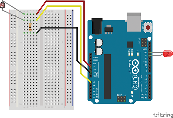
Figure 3-5: Wiring diagram for the Dark-Detecting Light.
This setup—power to sensor, and then sensor to both a ground and a measurement hole—is incredibly common when you’re working with Arduinos and sensors. So here’s a little chart to come back to if you need a reminder later:

Figure 3-6: A common sensor circuit, with power going through the sensor to both a measuring point and to ground.
Load Up the Code
Once again, the code we’ll use comes with your Arduino software, so it’s easy to load up. Navigate to the “AnalogInput” sketch by going to the menu bar and choosing File → Examples → 03.Analog → AnalogInput.
When it’s on your screen, upload the code to your Arduino by pressing the arrow button at the top of the blue window or using Sketch → Upload. Check the “Load Your Code” section of the previous project if you need a refresher.
Make It Go
After a bunch of quick flashes of the LED, the program will start up and your LED will blink at a steady pace. Cover the photoresistor with your hand and see what happens.
The LED should blink at a fast, urgent pace when it’s dark around the photoresistor, and should slow down when there is light present. Aim the photoresistor at a bright window or get it close to a bright bulb and it should slow down even more.
Fixes
If that’s not happening, check your steps, being mindful these things:
- The LED’s legs are different lengths. The longer one goes into hole
13. The shorter one goes intoGND. - No electricity flows across the breadboard canal. Be sure all of your connections are on one side.
- The wires and legs should be pushed firmly into the breadboard.
- It’s easy to slip the legs into the wrong row on the breadboard. If you’re following the wire-color conventions, you should see . . .
- A photoresistor leg and the red jumper wire in Row 1
- The other leg of the photoresistor, a leg of the static resistor, and a yellow jumper wire in Row 3
- The other leg of the static resistor and the black jumper wire in Row 7
What’s Going On?
Even if you’ve never read code before, you can sort of see what’s going on—especially because there are helpful human notes following the // characters.
The code inside the brackets labeled void loop() will repeat forever until you pull the power from the Arduino.
Just like the last chapter, the on and off pattern is paused by the delay() command. But this time, instead of a static number like 1,000, the delay changes depending on the value from the sensor, which is represented by sensorValue.
Let’s walk through this. In low light . . .
- The photoresistor doesn’t conduct electricity as well (it’s more resistant), so less electrical voltage gets back to the Arduino’s
A0pin. - That gets detected as a low
sensorValuenumber. - Which means less of a delay between the LED’s on and off states.
- Which makes the LED flash faster.
And in bright light . . .
- The photoresistor conducts electricity better (it’s less resistant), so more electrical voltage passes through it and back to the Arduino.
- That registers as a high
sensorValuenumber. - Which means more of a delay where there’s
delay(sensorValue)in the code. - Which makes the LED flash slower.
Code Corner
Take a look at the code we’re using, and you’ll see a little bit more than just the void setup() and void loop() sections. Here’s the whole program:
/*
 Created by David Cuartielles
 modified 30 Aug 2011
 By Tom Igoe
 This example code is in the public domain.
 http://www.arduino.cc/en/Tutorial/AnalogInput
 */
int sensorPin = A0;    // select the input pin for the potentiometer
int ledPin = 13;      // select the pin for the LED
int sensorValue = 0;  // variable to store the value  from the sensor
void setup() {
  // declare the ledPin as an OUTPUT:
  pinMode(ledPin, OUTPUT);
}
void loop() {
  // read the value from the sensor:
  sensorValue = analogRead(sensorPin);
  // turn the ledPin on
  digitalWrite(ledPin, HIGH);
  // stop the program for <sensorValue> milliseconds:
  delay(sensorValue);
  // turn the ledPin off:
  digitalWrite(ledPin, LOW);
  // stop the program for for <sensorValue> milliseconds:
  delay(sensorValue);
}
At the very top, we have a block of comments set off by /* and */. Again, those are ignored by the Arduino software.
And then right below the comment block, there’s a section where several words get assigned numbers. Huh? Yeah. These are called variables. Here’s the code in Arduino:
int sensorPin = A0;    // select the input pin for the potentiometer
int ledPin = 13;      // select the pin for the LED
int sensorValue = 0;  // variable to store the value  from the sensor
Ignoring the comments for a moment, here’s the code in English:
Hey Arduino, when you see the word "sensorPin," use Arduino Pin A0 instead.
When you see the word "ledPin," use the number 13 instead.
And when you see the word "sensorValue," use the number 0 instead.
Two quirky things here. First, the int at the beginning of each line means the word will be storing an “integer”—a whole number like 1, 2, –3, or 0. The strange thing is that in Arduinoland pin numbers like A0 are considered integers. Go figure.
The second thing is that these assignments aren’t permanent; we can change them in the code. In the code for this project, sensorPin and ledPin don’t actually change. But sensorValue does! It starts out as 0, but gets changed to the value read in from the sensor. This changeability is why these words are called variables.
Taking It Further
Tinker with the Resistor
Try using static resistors of different values instead of the 10K-ohm (10KΩ) resistor. What happens? Can you explain why?
See the Sensor’s Value
You can actually watch the value of sensorValue if you’d like. You just have to add two lines of code, which are easy to type in yourself. The first one is Serial.begin(9600); and it goes in the void setup() section, within the curly brackets, like this:
void setup() {
  // declare the ledPin as an OUTPUT:
  pinMode(ledPin, OUTPUT);
  Serial.begin(9600);  // < - - New line is here
}
The second one is Serial.println(sensorValue); and it goes within the curly brackets in the void loop() section, like this:
void loop() {
  // read the value from the sensor:
  sensorValue = analogRead(sensorPin);
  // turn the ledPin on
  digitalWrite(ledPin, HIGH);
  // stop the program for <sensorValue> milliseconds:
  delay(sensorValue);
  // turn the ledPin off:
  digitalWrite(ledPin, LOW);
  Serial.println(sensorValue); // < - - New line is here
  // stop the program for for <sensorValue> milliseconds:
  delay(sensorValue);
}
Type the lines exactly as they appear, being mindful of the capital letters (case matters) and the end-of-line semicolon.
- Upload the edited code to your Arduino.
- Open the Arduino software’s Serial Monitor window from the menu bar: Tools → Serial Monitor. This allows you to watch some of the communication from the Arduino itself.
- A window will appear with the
sensorValuenumbers! (If you see nothing, or see gibberish, be sure the menu at the bottom of the Serial Monitor window is set to “9600 baud.”) - Cover the photoresistor with your hand and see the numbers change.
Now you can see exactly how the Arduino is turning the light measurements into numbers!