
With an independent processor on the CryptoCape, we can create some interesting applications. Since the ATmega cannot be flashed from the BeagleBone unless the physical jumpers are attached to the board, we can consider this to be a trusted processor. In this project, we'll implement a biometric authentication system with a fingerprint sensor and the CryptoCape. We'll use the ATmega to prevent access to the security ICs on the CryptoCape until you have authenticated yourself to the ATmega with your fingerprint.
A notable example of fingerprint biometrics in consumer devices is Apple's Touch ID technology on the iPhone 5s. The sensor used on the iPhone is much more sophisticated and expensive than the sensor we will use in this project. But by performing this project, you should appreciate the capabilities and challenges of using biometric technologies. On the Touch ID support page, Apple motivates the use of the technology with the argument that unlocking the phone with your fingerprint is more secure than having no passcode and easier than entering a code each time. In a later section, we'll discuss the weakness of biometric systems.
The major components needed for this project are listed in the following table. The SparkFun parts are listed as they were the ones used, but feel free to substitute equivalent components. The CryptoCape, which is only manufactured by SparkFun Electronics, is open source hardware and the board design files are licensed under a Creative Commons license, so you could also make your own CryptoCape if you wish. You will also need a basic soldering station and appropriate accessories.
|
Component |
SparkFun SKU |
|---|---|
|
Fingerprint sensor |
SEN-11792 |
|
CryptoCape |
DEV-12773 |
|
JST jumper wire assembly |
PRT-10359 |
|
Female jumper wires |
PRT-11710 |
|
Male breakaway headers |
PRT-00116 |
|
2-pin jumpers |
PRT-09044 |
The following components are optional, but are nice to have:
|
Component |
SparkFun SKU |
|---|---|
|
Heat shrink kit |
PRT-09353 |
|
Third hand |
TOL-09317 |
|
Heaterizer XL-3000 |
TOL-10326 |
The Fingerprint sensor is the GT-511C3 device from ADH Technology. This device contains an optical sensor for reading the fingerprints but also an ARM Cortex M3 processor for computing the image recognition. The interface to this device is via serial UART, using 3.3V level logic, and at a baud rate of 9600 bps. There are four wires to connect from the JST connector: transmit, receive, GND, and power.
The datasheet states that the false acceptance rate is less than .001 percent and the false rejection rate is less than .1 percent. In short, this is a very capable fingerprint sensor. The fingerprint data is analyzed and stored on this device. We will use an existing library to communicate with this hardware.
Realize that this fingerprint sensor authentication mechanism is only as strong as your fingerprint. A common critic against using fingerprint sensors centers around the fact that it is difficult for you to change your fingerprint. Once your fingerprint is copied you can't revoke or change it as you can with a password. Using a fingerprint as a two-factor mechanism slightly reduces the risk of an authentication breach since a pin or password is still required. You can also mitigate the risk of a fake fingerprint attack on your sensor by stationing an armed guard to watch the sensor as Bruce Schneier, a security technologist, stated in a September 2013 opinion article in WIRED magazine. Such luxuries are often limited to deep-pocketed governments.
Note
Mythbusters, a popular science and engineering program on the Discovery Channel, busted the myth that fingerprints could not be copied and showed how to defeat fingerprint sensors: https://www.youtube.com/watch?v=3Hji3kp_i9k. Also, days after the Apple iPhone 5s was released, the biometrics hacking team of the Chaos Computer Club (CCC) showed how to bypass the fingerprint sensor: http://www.ccc.de/en/updates/2013/ccc-breaks-apple-touchid.
Perhaps the greatest danger of biometric systems is the potential for a grave privacy breach. A database of fingerprints should be well protected since once the fingerprints are exposed they are no longer useful for any other biometric system, ever. In August 2014, Hold Security, an information security forensics company, reported to the New York Times that over 1.2 billion usernames and passwords were acquired by a Russian crime organization. While incredibly damaging, this breach would be irrecoverable if fingerprint biometrics were used. Hopefully, companies aren't storing fingerprints directly but representations of the fingerprint similar to a hash digest. However, if implemented poorly, the results can be as disastrous as storing the raw fingerprint.
With these warnings in mind, we will continue with using a fingerprint sensor for this project. You'll gain insight on how a fingerprint sensor works and how to it fits into an authentication system. When you are finished with this project, however, you should probably delete your fingerprint from the sensor's database.
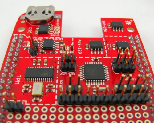
In order to make the CryptoCape more hackable, we need to populate the pads attached to the I/O signals with male headers. This will allow us to connect various external components. While you could directly solder to the pads, it's best if you solder a male 0.1" pin, which will allow you to easily connect a female terminated wire for your project, which can then be reused.
A fully populated CryptoCape will look like the following image. A strip of breakaway headers of 31 pins or more will be enough to populate each pad. Technically, you don't need to populate the EEPROM write protect pads unless you want to write to the EEPROM. However, if you overwrite the EEPROM cape information, the BBB might not load the correct drivers.
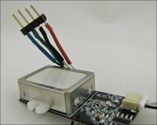
Before attaching any connections, we physically need a method to attach the ends of the JST cable to the CryptoCape. The CryptoCape has 0.1" pads, which will fit 0.1" male headers and female-to-female jumper wires fit nicely to that connection. One end of the JST connector is simply four bare wires. If you solder each of these wires to a 4x1 0.1" male header, you can make a simple connector. Using a third hand, you can solder the JST wires to the headers and for a finishing touch, add heat-shrink around the wire and the male pin. Just remember to put your heat shrink on before you solder! The completed connector should look something like this:
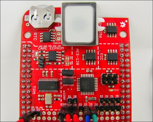
We'll attach the fingerprint scanner to the CryptoCape. The Arduino compatible library for this sensor was developed by Josh Hawley. This library is configured to use digital pin 4 for the receive pin on the ATmega and digital pin 5 as the transmit pin from the ATmega. These pins are appropriately labeled D4 and D5 on the CryptoCape, just under the ATmega. The remaining two pins are 3.3V power and ground which are also on the same row as the D4 and D5 pins. Attach the female ends of the jumper wires to these pins. If you are using the SparkFun JST connector, the pins from the fingerprint scanner are in the following order, starting with the black wire: D4, D5, GND, Power.
The fingerprint sensor must be trained to recognize your fingerprint through a process called enrollment. There are several methods to enroll your fingerprint. The SparkFun website has instructions on how to use the ADH-Tech provided Windows-based software to program the sensor. However, you'll need an extra component, that is, the FTDI Basic Breakout board to convert USB from your computer to serial for the scanner. You could also use an Arduino directly, but you must also use logic level converters if you are using a 5V Arduino. Since the CryptoCape has an Arduino compatible processor, we will show you how to do this with your BBB and CryptoCape. The repository that contains the ATmega firmware can be cloned on your BBB with the following command:
git clone https://github.com/jbdatko/Fingerprint_Scanner-TTL.git
In this repository, the FPS_Enroll.ino file will enroll, or add, a fingerprint to the sensor's database. As previously mentioned, you'll need to compile this file out of band. Alternatively, you can use the pre-compiled version in the repository above.
Upload the enroll script:
sudo ./upload.sh FPS_Enroll.cpp.hex
You should see text scroll by that looks like this:
Reading | ################################################## | 100% 0.00s

avrdude: Device signature = 0x1e950f
avrdude: safemode: lfuse reads as 0
avrdude: safemode: hfuse reads as 0
avrdude: safemode: efuse reads as 0
avrdude: NOTE: FLASH memory has been specified, an erase cycle will be performed
         To disable this feature, specify the -D option.
avrdude: erasing chip
avrdude: reading input file "FPS_Enroll.cpp.hex"
avrdude: input file FPS_Enroll.cpp.hex auto detected as Intel Hex
avrdude: writing flash (11458 bytes):

Writing | ################################################## | 100% 3.09s

avrdude: 11458 bytes of flash written
avrdude: verifying flash memory against FPS_Enroll.cpp.hex:
avrdude: load data flash data from input file FPS_Enroll.cpp.hex:
avrdude: input file FPS_Enroll.cpp.hex auto detected as Intel Hex
avrdude: input file FPS_Enroll.cpp.hex contains 11458 bytes
avrdude: reading on-chip flash data:

Reading | ################################################## | 100% 2.21s

avrdude: verifying ...
avrdude: 11458 bytes of flash verified

avrdude: safemode: lfuse reads as 0
avrdude: safemode: hfuse reads as 0
avrdude: safemode: efuse reads as 0
avrdude: safemode: Fuses OK

avrdude done.  Thank you.
If there is a problem, first check to see whether the jumpers are attached and then try again.
This script will output to the serial port at 9600 baud, so we need to change /dev/ttyO4 to reflect this:
sudo stty -F /dev/ttyO4 9600
Finally, let's display the output of the serial port with:
cat /dev/ttyO4
The script is patiently waiting for you to enroll a finger. Place your finger on the reader and watch the output of the serial port and follow the instructions. A successful enrollment looks like this:
Remove finger
Press same finger again
Remove finger
Press same finger yet again
Remove finger
Enrolling Successful
If there is a problem, and the enrollment process can be a bit finicky, you'll need to reset the ATmega and re-attempt enrollment. In the same repository is a script, reset.sh, that simply toggles the ATmega reset line. If you have troubles, reset your ATmega and try again.
With the sensor now trained to recognize your fingerprint, we'll upload a sketch that will lock out the CryptoCape until you present your fingerprint. Specifically, it will prevent access to the chips on the CryptoCape from the BBB. We'll accomplish this by jamming the SCL line on the I2C bus.
One weakness of I2C is that one misaligned device can disrupt the entire bus. On the CryptoCape, every IC is connected to the same I2C bus. We'll exploit this for this project. The ATmega will hold the SCL low until a successful fingerprint is received. This essentially jams the bus since the master, the BBB, can't generate the start condition.
The software running on the BBB will hang until the ATmega releases the lock. Typically, this is a very undesirable effect. For this project, however, it illustrates how two microprocessors can interact and even interfere with one another. In the following screenshot, you can see the effect of this jamming of Salee Logic Analyzer software. Once the SCL is released, the BBB is finally able to send a start condition.

In the FPS_CryptoCape.ino file, this is accomplished by setting digital output 2 as an output and then pulling the line low. When a fingerprint is recognized, the pin is configured as an input, which prevents the ATmega from pulling the line either high or low and allows normal I2C operation.
Add a jumper wire from D2 on the ATmega breakout pads to the SCL pad near the TPM on the CryptoCape. This is that one extra wire that will allow the ATmega to lock out the BBB's access to the I2C bus. Once you add that wire, upload the FPS_CryptoCape.cpp.hex, which you can either compile yourself or use the pre-compiled version. The wires on your CryptoCape should look like the following image:
Upload the sketch as before and then listen to the serial port with the same cat /dev/ttyO4 command. You will see the ATmega waiting for the sensor's fingerprint. Present your fingerprint to the sensor and it will then print a verification when complete:
Please press finger
Verified ID:0
You will also notice that the green LED on the CryptoCape will turn off. While the LED is on, the ATmega is locking out your BBB from accessing the CryptoCape.
How secure is our biometric system? While it does prevent software on the BBB from using the CryptoCape until a valid fingerprint is accepted, the system is easily defeated by pulling (or cutting) the line from D2 to SCL. Without the electrical connection, the ATmega can't interfere with the I2C bus. However, depending on your installation, an attacker may have a difficult time physically accessing the hardware. The process of assessing vulnerabilities and mitigations to those vulnerabilities is known as threat modeling. In the previous chapter, the Tor design stated that it can't defend against a global passive adversary. In your implementation of our biometric system, maybe access to the jamming line is not a threat because you've placed your BBB in an adamantium box. There is no perfectly secure system so a threat model helps us understand the strengths, weaknesses, and assumptions of our system. We'll see more threat modeling in our final two chapters.