
Now, it's time for some serious construction in order to actually fit our project to the door. Mind you, this project was based on a standard lock used in Sweden; if you have a different door lock, this design might need some heavy modification. The goal was to keep the design of the construction as simple and transparent for this reason. I would suggest that you start by taking a look at Figure 6.8 to get a general idea of the finished result before you get started.
In Figure 6.5, you will find the design measurement for the construction that holds the motor, shield, and Arduino board in place:
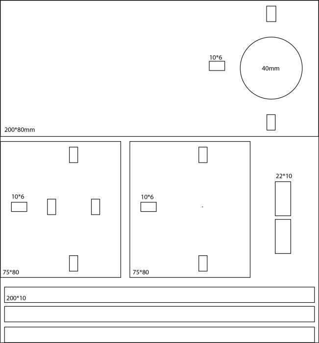
Figure 6.5: The cutting measurements for all the parts
The largest piece, which measures 200 x 80 mm, will act as our baseplate. The idea is that the front of the lock will be removed and then the baseplate will be inserted on the door. The front of the lock will then be put back into place, which will hold the baseplate in place. In this way, you don't have to modify the door in anyway or drill screws into the door to keep it in place. Drilling screws into the door is an easier option but most door locks can easily be unscrewed from the inside, so I do not recommend that you parentally fix anything to the door since these might be expensive to replace. The 75 x 80 mm piece to the left in Figure 6.5 is where the motor will be place. The 22 x 10 mm pieces will be inserted into the middle holes of this piece in order to hold the motor in place. Figure 6.6 should give you an idea of what this will look like. The second 75 x 80 mm piece to the right of the first one will only be used for steadiness. Both the 75 x 80 mm pieces and the 200 x 80 mm have three identical holes, which are placed in the same location. The idea is to run the three 200 x 10 mm pieces in order to make "floors" in the construction and hold everything together, which is also shown in Figure 6.5. The 200 x 10 mm pieces are longer than needed, but this will give you room to move things around if needed to get the right distance between the lock and motor. Once you are done, you can cut them into the right size.
Note that this design is based on a material that has a thickness of 6 mm. If you use any other material thickness, the pieces will not fit the holes. For this project, I used MDF since it's affordable and easy to use with a laser cutter. Even if it is possible to cut all the pieces by hand, I would recommend using a laser cutter for this project. If you don't have access to one, I would recommend that you use the design as a general guideline for how it can be done, but try to rethink the design so it fits with the tools and material available to you.
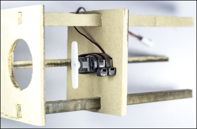
Figure 6.6: The motor plate in place together with the base plate
The measurement for the "claw" in Figure 6.7 is 40 x 40 mm on all three pieces. However, I recommend that you make a few of them to try out with your own lock. The general guideline is that you don't want a snug fit between the lock and the "claw," since then, the axel of the motor needs to be perfectly aligned with the locks rotational axel. If you give it some room, the alignment does not need to be perfect. This makes the rest of the construction easier. Figure 6.7 shows the "claw" that will be attached to the servo motor and placed over the actual lock:

Figure 6.7: The "claw" attached to the servomotor
The motor can be attached using either the screw mount on the actual motor or using plastic straps. I choose to use plastic straps, since again this gives the motor some room to move a little bit in case the axels don't align perfectly. But make sure not to strap it in too loose so that the motor falls out. Servomotors usually come with some different attachments for connecting them to other things and in Figure 6.7 you can see the type of leaver I used for this project. This was simply screwed into the bottom of the "claw."
The process for putting everything together, I recommend, starts with attaching the baseplate to the door. Place the motor plate in the right position so it covers the lock, and make sure it's able to twist the lock. Then attach the last plate if some extra sturdiness is needed, and hopefully you'll end up with something that looks like Figure 6.8. The Arduino and shield is held into place using straps, since this is safer than attaching it with screws. You can use the screw holes on the NFC shield, but watch out so you don't scratch the PCB since this might cut one of the PCB connections. For this project, I cut the JST connector off the motor cable and soldered them to the NFC shield, which has an extension pin for all the pins on the Arduino board. The connections are the same as used before where the signal pin is connected to digital pin number 9 and the black cable to GND and the red one to 5V:
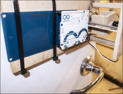
Figure 6.8: The final door lock in place