
9
Design Communication – Inventor Studio, Animation, Rendering, and Presentation Files
A successful design project can be measured by how well the benefits and the solution are communicated and understood by the stakeholders. Therefore, being able to visualize designs in 3D within Inventor is highly important. Designers need to be able to render, animate, and sometimes quickly annotate parts and assemblies to communicate key design changes, updates, and showcase product features.
This chapter focuses on how a designer can implement renderings, explode views with presentation files, and create animations. The chapter also focuses on some of the basic areas of Inventor rendering, animation, and design change documentation. This will aid the designer in all aspects of product and concept presentation. Although Inventor can produce good rendered images/animations, it is not a specific tailored rendering application. In this respect, there are limitations, but for most mechanical design engineers, the functionality within Inventor is more than enough for what is required.
If more advanced rendering and animation are required as part of your workflow on a regular basis, I highly recommend Autodesk 3Ds Studio Max (interoperable with Inventor models). 3ds Max is a visualization tool, used to model, animate, and render.
In this chapter, you will learn the following:
- Creating an image render with Inventor Studio
- Animating components of an assembly in Inventor
- Presentation files – creating exploded views and animations of assemblies
- Creating and adding decals and custom appearances
This chapter also aims to give insight and advice on setting up renders for success and the technical and hardware requirements that may limit your rendering capabilities.
Technical requirements
To complete this chapter, you will need to access the practice files in the Chapter 9 folder within the Inventor Cookbook 2023 folder.
Creating an image render with Inventor Studio
Inventor Studio is a rendering and animation environment within the Autodesk Inventor part and assembly environment. With Inventor Studio, you can do the following:
- Create still and animated renderings of parts and assemblies
- Create still and animated renderings of products to show visual changes and/or movement within an assembly
- Create video animations using multiple cameras
- Reuse constraints or parameters between animations in one assembly file to drive and show movement, and much more
Inventor Studio works with model states and design representations. Before entering the Inventor Studio environment, it is good practice to have the model state you wish to animate or render active in the model.
With the rendering command, you can run this as standard with the part or assembly that is open, with no enhancements to the geometry, or you have the option to assign additional lighting styles, scenes, camera viewpoints, and materials. For quick design reviews or presentations, a full-scale render with cameras and lighting enhancements is not always required.
Various factors affect the end quality of the render; these include but are not limited to anti-aliasing, output resolution, material and bitmap selection, and geometry of the model. The end-specified image size and machine performance are also factors in render quality, as a larger image requires more machine resources and time (these factors also apply to rendered video output).
Anti-aliasing
Anti-aliasing is the process of smoothing jagged edges in digital images.
When a render is executed, the rendering progress is displayed in a separate window from the model. Inventor renders images locally on your machine, but other Autodesk solutions such as Fusion 360 can render on the cloud.
You can save rendered output to standard formats: .bmp, .gif, .jpg, .jpeg, .tif, .tiff, and .png.
Custom lighting and materials can be created and saved into your Template and Libraries folders for future use.
In this recipe, you will render a realistic image of a model that has had a custom appearance, lighting, and camera customization assigned. We will start by applying appearances and materials to the geometry model. Lighting styles will then be defined, followed by shadows, cameras, and rendering options.
Getting ready
To begin this recipe, you will need to navigate to Inventor Cookbook 2023 | Chapter 9 | Assy Mini Drone, and then open Assy Mini Drone.iam.
How to do it…
To begin, ensure that you have the Assy Mini Drone.iam file open in Inventor. The first step will be to apply the relevant appearances to the model and override the material display:
- Open Assy Mini Drone.iam.
- In Model Browser, select Frame.
Once selected, note that in the Materials toolbar, PBT Plastic is displayed. This is the material that has been specified previously to the part. Even though a material has been specified, you can override the appearance of that material with the Appearance browser.
- To do that, in the Quick Access toolbar, select the Appearance Browser command.
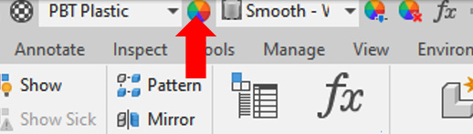
Figure 9.1: Appearance Browser
- Within the Appearance Browser, you can search and specify what appearance to apply to the highlighted part. These are libraries within Inventor that contain a list of pre-defined appearances (there is also an equivalent for materials). In the Search field, type Metal 1600F Hot.
- The list populates results, and the specific appearance is available for selection. Hovering the cursor over this provides a preview in the Graphics window of the appearance applied.
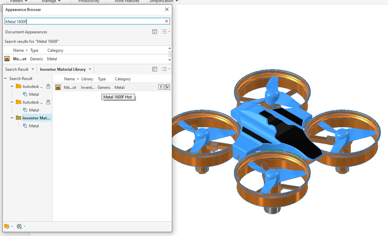
Figure 9.2: The Metal 1600F Hot appearance applied
- Right-click on Metal 1600F Hot in the Appearance browser and select Assign to Selection. The frame changes its appearance to this material.
- Close the Appearance browser.
- Then select Casing from Model Browser and open the Appearance browser again.
- Type Orange in the Search field and select Smooth – Light Orange. Right-click on Smooth – Light Orange and select Assign to Selection.
- With the Appearance browser still open, hold Ctrl and select the Casing from the Model browser to deselect this from the current selection. Then, still holding Ctrl, select all four instances of Propeller from Model Browser.
- Assign a Smooth Red material to the propellers.
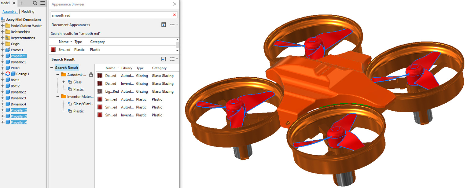
Figure 9.3: Smooth Red applied to the propellers
- Ground Plane, Reflections, and Shadows now need to be defined. Click on the View tab. In the Appearance panel, select the dropdown next to Ground Plane. Select the checkbox to activate Ground Plane.
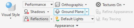
Figure 9.4: Ground Plane
- Select LEFT on the view cube; the model should be level on the ground plane, as per Figure 9.5. It is important that this is correct; otherwise, shadows and reflections will not render accurately. If your model does not display this way, go to the Ground Plane settings and select Automatic adjustment to model, and then Apply.
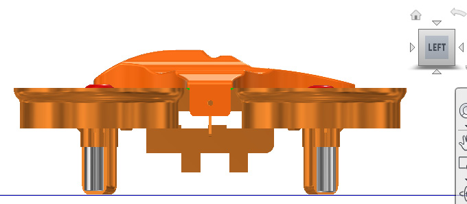
Figure 9.5: The ground plane activated, with the model set correctly
- From the View tab, select Appearance, and then select Reflections to enable the reflections. The Graphics window will display this.
- In the View tab, select Appearance, then select Orthographic, and change it to Perspective.
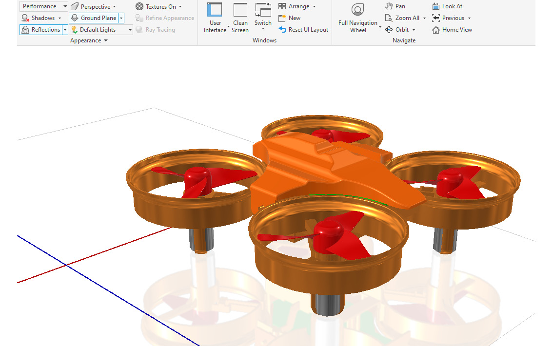
Figure 9.6: The Perspective view activated and turned on
- Select Default Light and then Warm Light from the pre-defined drop-down list. This list contains a standard library of default lighting systems that can be applied; custom lighting styles can also be created and stored here.
- Select the Environments tab, and then Inventor Studio.
- From the rendering tools, we can further specify cameras, lighting, and components to animate. Select Studio Lighting Styles in the Scene panel of the ribbon.
- Browse the lighting styles and environments, and select Warm Light. Right-click on Warm Light and select Activate.
- Tick the checkbox next to Display Scene Image to include the scene with the lighting style in the rendering environment.

Figure 9.7: The Warm Light lighting style and the scene active
- Select Done, followed by Yes, when prompted to save.
- Select Render Image from the ribbon.
- Maintain the settings in General as default, and select the Output tab. Select Save Rendered Image and browse to the Mini Drone folder in Chapter 9. Select Save.
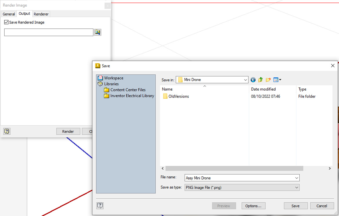
Figure 9.8: The location to save the completed rendered image
- In the Render Image dialog box, select the Renderer tab. Then, select Until Satisfactory as the duration.

Figure 9.9: The Renderer settings to apply
- Select Render. The render output window will open, and the image will begin to render. The longer the rendering process is given, the better the quality of the image. You can pause the renderer at any time if you deem that the image is satisfactory. After around 7 minutes, your rendered image should resemble Figure 9.10. Select Stop Render and save the image. Close the Inventor assembly and do not save.
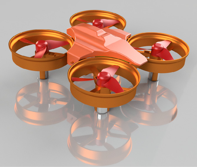
Figure 9.10: The completed render
A successful still image render of Mini Drone.iam with lighting styles, environments, and appearance override has been created. Renders are often quite an iterative process, and to get the right image, it may take several renders and tweaks to lighting styles, cameras, and appearance choices to get the desired outcome or hero image of the product that is required. This recipe has shown that even with minimal input, a reasonable design visualization can be generated.
Animating components of an assembly in Inventor
In this recipe, you will create an animation of a drone assembly that shows the quad propellers spinning as it vertically takes off. Camera animations, lighting, and scenes will be applied, and then the end output exported through Video Producer as a .avi video.
Getting ready
To begin this recipe, you will need to navigate to Inventor Cookbook 2023 | Chapter 9 | Drone Animation and open Assy Mini Drone.iam.
How to do it…
To begin, ensure that you have the Assy Mini Drone.iam file open in Inventor. All appearances and relationship constraints required to drive and create the animation have already been applied:
- Click on the Environments tab from the ribbon and select Inventor Studio.
- We want to establish our scene and lighting. In this example, we will use one of the existing lighting and scene styles. Select Studio Lighting Styles from the Scene panel.
- Right-click on Empty Lab from the list and select Active.

Figure 9.11: Activating the lighting and scene styles
- Select the checkbox next to Display Scene Image. Then, zoom out using the mouse wheel. Displaying the scene with this lighting style shows an empty laboratory with the drone assembly on a table; zoom out using your curser wheel to see this.
- In the Environment tab of the Studio Lighting Styles menu, change the Scale % value from 100.000% to 30.000%. This makes the scene smaller, and the drone appears much larger.
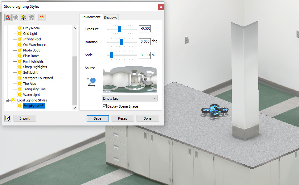
Figure 9.12: The scene scale changed from 100% to 30%
- Next, we will adjust the scene rotation so that it is more suitable for our animation. In the Rotation section, change the value from 0.000 degrees to 180.000 degrees to rotate the scene.
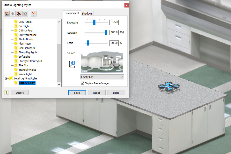
Figure 9.13: The scene rotated 180 degrees
- Select Done, followed by Yes.
- Now, select the View tab. In the Appearance panel, change the Orthographic view to Perspective.
- Orientate your view so that it resembles Figure 9.14.
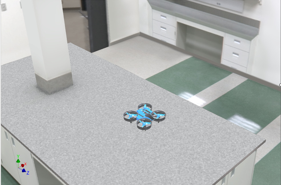
Figure 9.14: The view to orientate
- We can now make this Current view the Camera view for the animation. Select the Render tab, right-click Cameras in Model Browser, and select Create Camera from View. This creates a new camera view from which a render or video can be taken, based on the current view in the model space. Cameras can also be created manually with the Camera command.
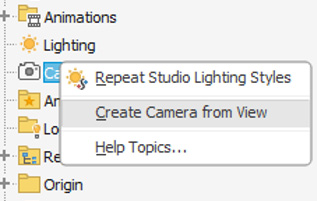
Figure 9.15: Create Camera from View
- Now that lighting and cameras are placed, we can specify how the animation will flow. Select Animation Timeline from the ribbon, followed by OK if prompted.
- The Animation timeline appears at the bottom of the screen. This is where your actions will populate once they have been created. Select the Animations Options command from the bottom right of the screen (highlighted in Figure 9.16).
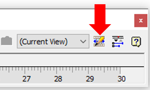
Figure 9.16: Animations Options
- In the Animations options, we can define specifics about how fast actions will run throughout the duration of the animation. In the Seconds area of the window, change the value from 30 seconds to 5 seconds. This is the length of time the animation will run. Select OK to complete.
- Now, we will animate the four propellers to spin. Select the Animate Constraints command, as shown in Figure 9.17. As there are directed angle mate constraints in place on the propellors already, we can use this directed angle constraint to drive and rotate the propellers in place.

Figure 9.17: The Animate Constraints command
- For the action, expand the first instance of the propellors in Model Browser, and select the angle constraint.
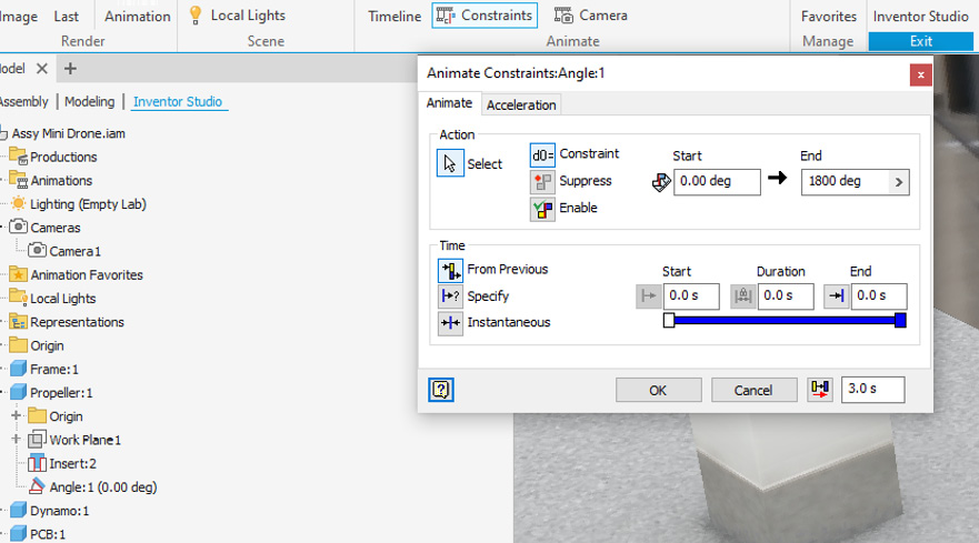
Figure 9.18: The directed angle constraint selected from Model browser
- For the End degrees, change the value from 0.00 to 1800.
- Under Time, select Specify. Then, change Start to 0.3 seconds and End to 5 seconds. Then, select OK.

Figure 9.19: Time specifications for the animation of the propellers
- Select Expand Action Editor, as shown in Figure 9.20. This expands the Animation timeline. You will see that the animate constraints for the directed angle constraint are visible on the timeline. Select the Play button from the timeline to preview and play the animation.

Figure 9.20: Expand the Animation timeline
- Only one of the propellors will spin at this stage, as we have only applied the animation to the constraint located in Propellor 1. For the other three propellors to spin at the same rate and speed, repeat steps 14–19 for each of the three remaining instances of Propellor.
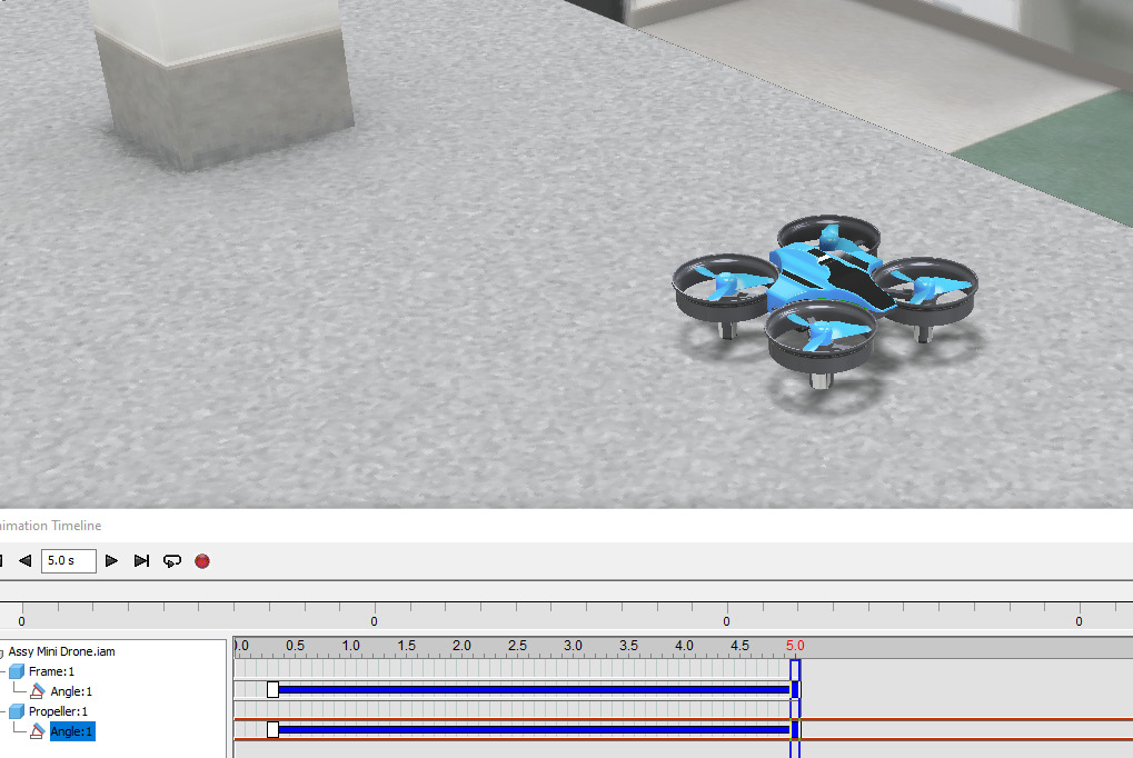
Figure 9.21: The Animation timeline expanded with actions visible
- We will now add an animation to several components in one operation that will move the mini drone vertically off the table as the propellers spin from the previous animation. As the first step, select Animate Constraints.
- Select Mate:3 under Frame in Model Browser as the constraint to animate.
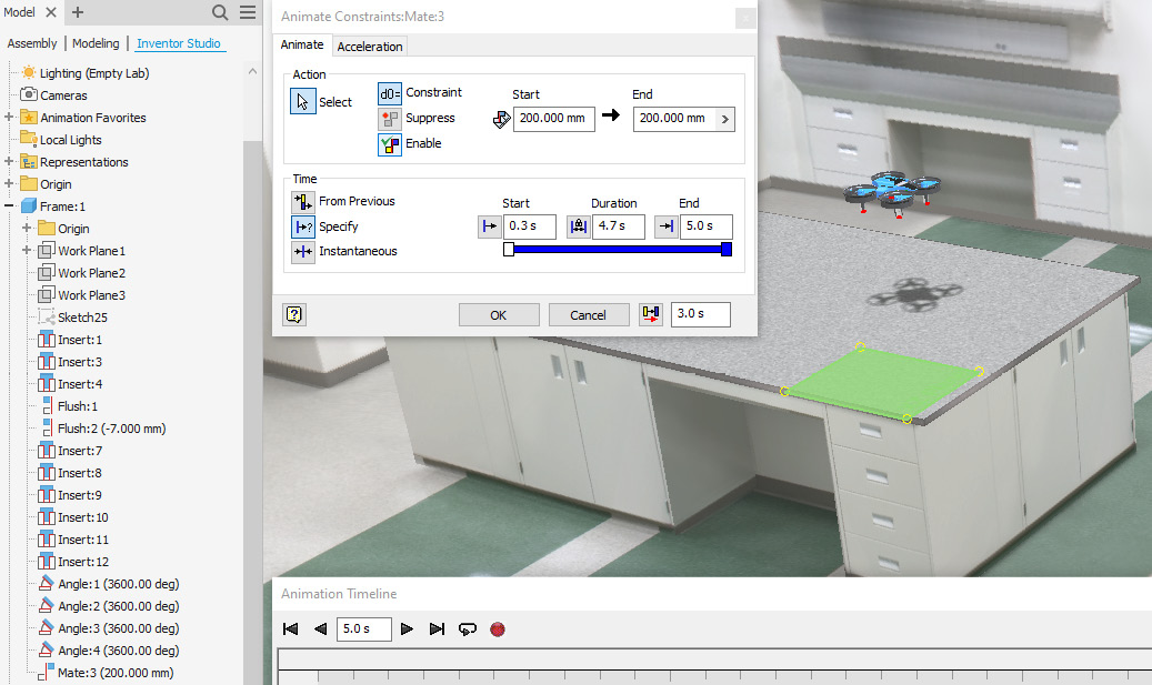
Figure 9.22: Mate 3 animated
- Ensure the Start value is set to 100.000 mm and type 200.00 mm as the End value. Then, select Specify under Time and set Start as 0.3 seconds and End as 5.0 seconds. Then click OK.
- Upon pressing Play in the Animation timeline, the mini drone will vertically take off 100 mm from the tabletop as the propellors spin. Select Play to view the animation.
- The camera that we previously created has not yet been used in this animation. Now, we will animate the camera so that it partially revolves around the mini drone as it takes off. To do so, select Animate Camera.
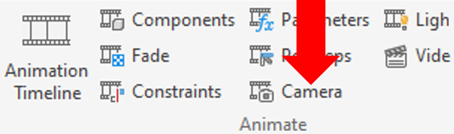
Figure 9.23: Animate Camera
- Once the Animate Camera dialog opens, ensure that under Camera, Camera 1 is selected as the active camera. Then, select the Turntable tab within the Animate Camera window.
- Select the checkbox next to Turntable. In the drop-down menu under Axis, select Y Origin.

Figure 9.24: Turntable and Y Origin selected
- Select +/- and change Revolutions from 1.000 to .65. Then, select OK to complete.

Figure 9.25: .65 revolutions specified
- In the Animation timeline, rewind back to the start. In the dropdown on the right of the Animation timeline, ensure that Camera 1 is selected.
Figure 9.26: Camera 1 selected
- Play the animation. The mini drone’s propellors should spin, and it should rise above the table as Camera 1 pans around it at .65 of a revolution in the Y axis. The preview may appear to lag; once the animation is rendered properly, this will be a much smoother transition.
- There is much more that can be done to tweak an animation, but in our case, we will now proceed to Render Animation to export and render the animation. Select Render Animation from the ribbon.
- Select the Output tab. Select Browse and save the file as a .avi file in the Drone Animation folder. Then, change Time Range to 0–5 seconds and increase Frame Rate to 25 frames per second.

Figure 9.27: Render Animation output
- Click on the Renderer tab. Change the iteration from 400 to 15 and the accuracy from High to Low. If you need a more polished render, increasing the iterations and quality will achieve this. For this recipe, low quality will suffice, as that will reduce the processing time.
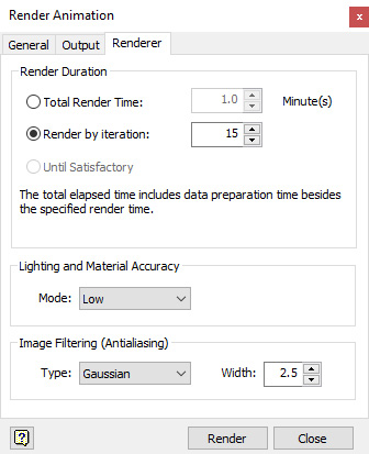
Figure 9.28: Renderer options
- This is optional, but you can click on Renderer. In the dropdown, select Uncompressed as the compressor, and then select OK.

Figure 9.29: Video Compression options
- The render will take a few minutes to complete each frame. Once finished, play the .avi video file created. Anytime in the Inventor Studio environment, you can navigate back to the Inventor Assembly environment and continue modeling or making changes. All settings and animations applied in the Inventor Studio environment will be contained within the part or assembly file.
Using Inventor Studio, you have successfully created an animation of a mini drone taking off vertically in an Inventor environment, with custom camera animations and lighting. The result has been exported as a .avi video format.
Presentation files – creating exploded views and animations of assemblies
Engineers and designers must frequently produce exploded views of products or assemblies to communicate design intent. Often, it is a requirement to produce an animation of this. Inventor has specific tools and file formats to enable the efficient creation of such animations. These are known as presentations.
Presentations (.ipn files) can be created from any assembly with two or more parts contained within it. In this recipe, you will create a presentation file of a toy figure, showing all its parts exploding outward. The result will be exported as a .avi video. The recipe will also show how you can use snapshot views within the Presentation environment to create an exploded view for a drawing file.
Getting ready
To begin this recipe, we will have to create a new .ipn file and then import LMan.iam into the presentation file. Once this is complete, we can start the process of creating an exploded animation of the product. You will need access to the LMan.iam file located in the Inventor 2023 Cookbook folder, the Chapter 9 folder, and then select Lman.iam.
How to do it…
To begin, we will need to create a new .ipn presentation file:
- From the Inventor Home screen, select New. Browse for Standard (mm).ipn and select Standard (mm).ipn, and finally, click on Create.

Figure 9.30: Creation of a new .ipn file
- Browse the following location when prompted, Inventor 2023 Cookbook | Chapter 9 | LMan, and then open LMan.iam. This imports the assembly file (.iam) into the presentation file (.ipn).
- LMan.iam opens within the Presentation environment. From here, we can now tweak components using a timeline to show parts exploding from the assembly. The opacity of parts can also be controlled. To begin the exploded view, we will start to tweak some of the components.
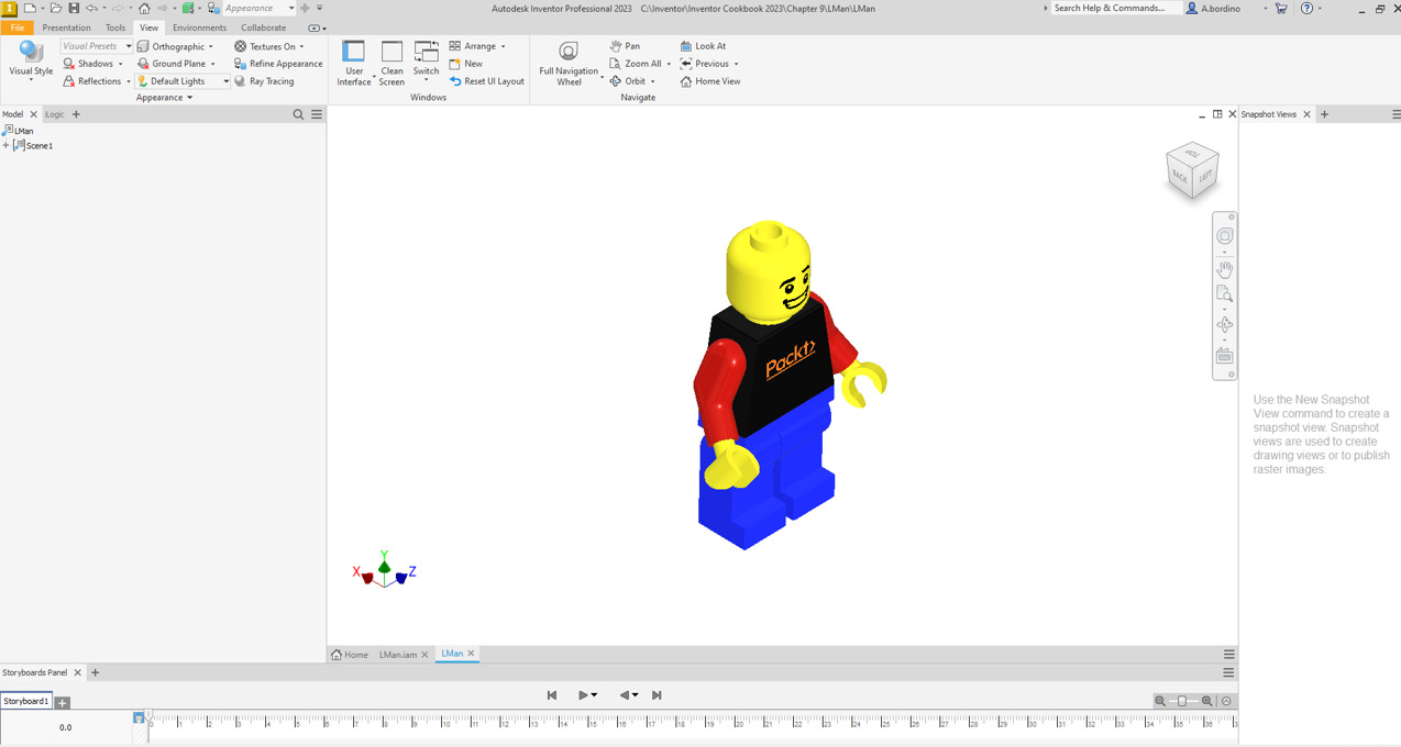
Figure 9.31: LMan.iam open in the presentation file
- Along the timeline, you will notice Storyboard 1 is active; this is the active storyboard we are working within. You can create multiple storyboards if required, but for this recipe, the default will be fine. At the top of the Presentation ribbon, select Tweak Components.
- Select LMan Head.ipt in the Graphics window.
- The following appears, as shown in Figure 9.32. Using the X and Y arrows, you can pull and push the component and control how you would like to animate it during the presentation. You can also type values and specify exactly the required movement. During a presentation file tweak, a part can either be moved or rotated.
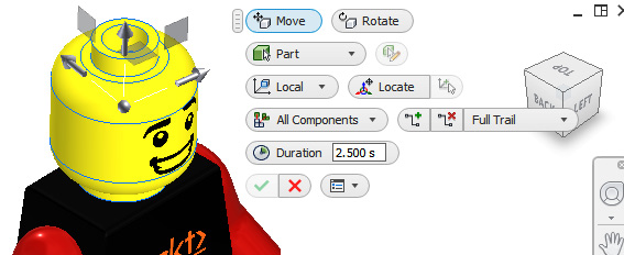
Figure 9.32: Tweak components active on Head.ipt
- Select the vertical arrow in the Graphics window on Head.ipt and pull upward. Type 40mm in Distance, and change Duration to 2 seconds. By keeping Full Trail active, a trail line will be left from where the part originated in the assembly. Then select the green tick.
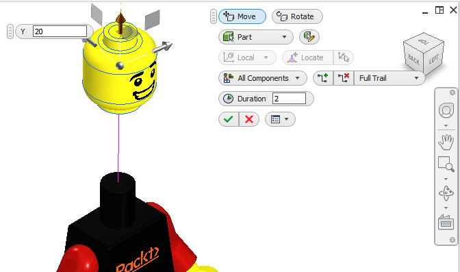
Figure 9.33: A tweak of Head.ipt
- The first tweak has been created and is populated in the storyboard. Within the storyboard area, tweaks can be edited and moved in the animation.
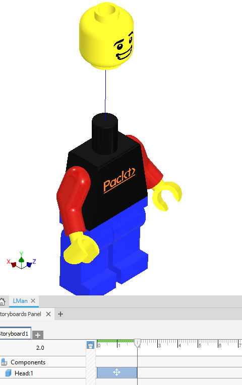
Figure 9.34: Tweak completed and visible in the storyboard
- Select Play in the timeline, and the animation will commence, showing the head moving from the body.
- Now, select Tweak Components. Then, select Arm 1 and Hand 2 from Model Browser.
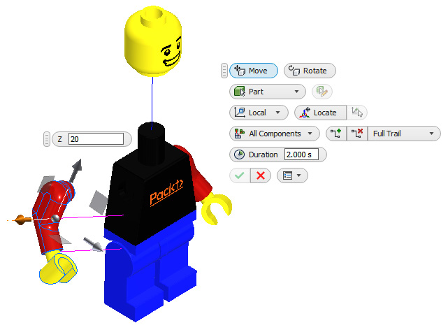
Figure 9.35: Arm and hand tweak applied
- Pull the horizontal arrow for the arm and hand, and type 20mm in Distance. Ensure Duration is kept at 2.000 seconds. Select the green tick to complete.
- Repeat steps 10–11 with the other arm so that the result resembles Figure 9.36.
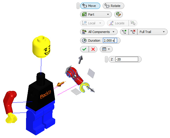
Figure 9.36: Second arm and hand tweak applied
- By default, each Tweak animation happens sequentially. In the storyboard, click and drag the animation blocks that represent the arm and hand tweaks, and place them so that they have the same start and end times. This will make each arm break off from the body concurrently in the animation. Figure 9.37 shows before and after examples. Click on Play to view the updated animation.

Figure 9.37: Before and after the tweaks’ manual adjustment within the storyboard
- Create two more tweaks of the Leg components so that this resembles Figure 9.38.

Figure 9.38: Two additional tweaks showing the leg components moving away from the body
- Now that the additional tweaks have been created, in the timeline, edit the animation blocks so that the legs move away from the body at the same time as the head and arms. Ensure that Duration for all movements is set to 2.000 seconds.
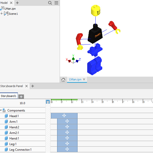
Figure 9.39: Timeline actions edited so that movement is all at the same time
- The animation at present is only 2.6 seconds long. Drag the animation blocks for all components in the timeline to 4.5 seconds to increase the time that these parts move.
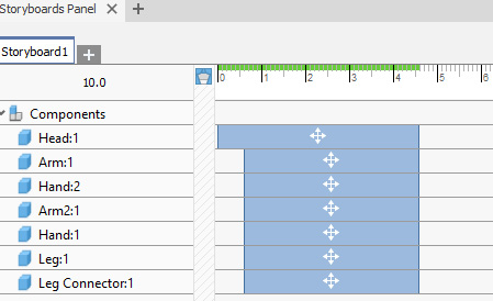
Figure 9.40: Edits to the animation blocks
- Press Play to view the animation.
If edits are required to the tweaks, they can be made in various ways; one of the easiest ways is to expand Model Browser, as shown in Figure 9.41.
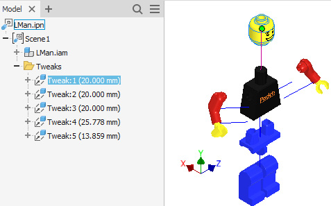
Figure 9.41: Tweaks created in Model Browser
- Now that the animation is complete, we can further refine the display options to get the best results. Center and change your view of the model so that it resembles that of Figure 9.42.
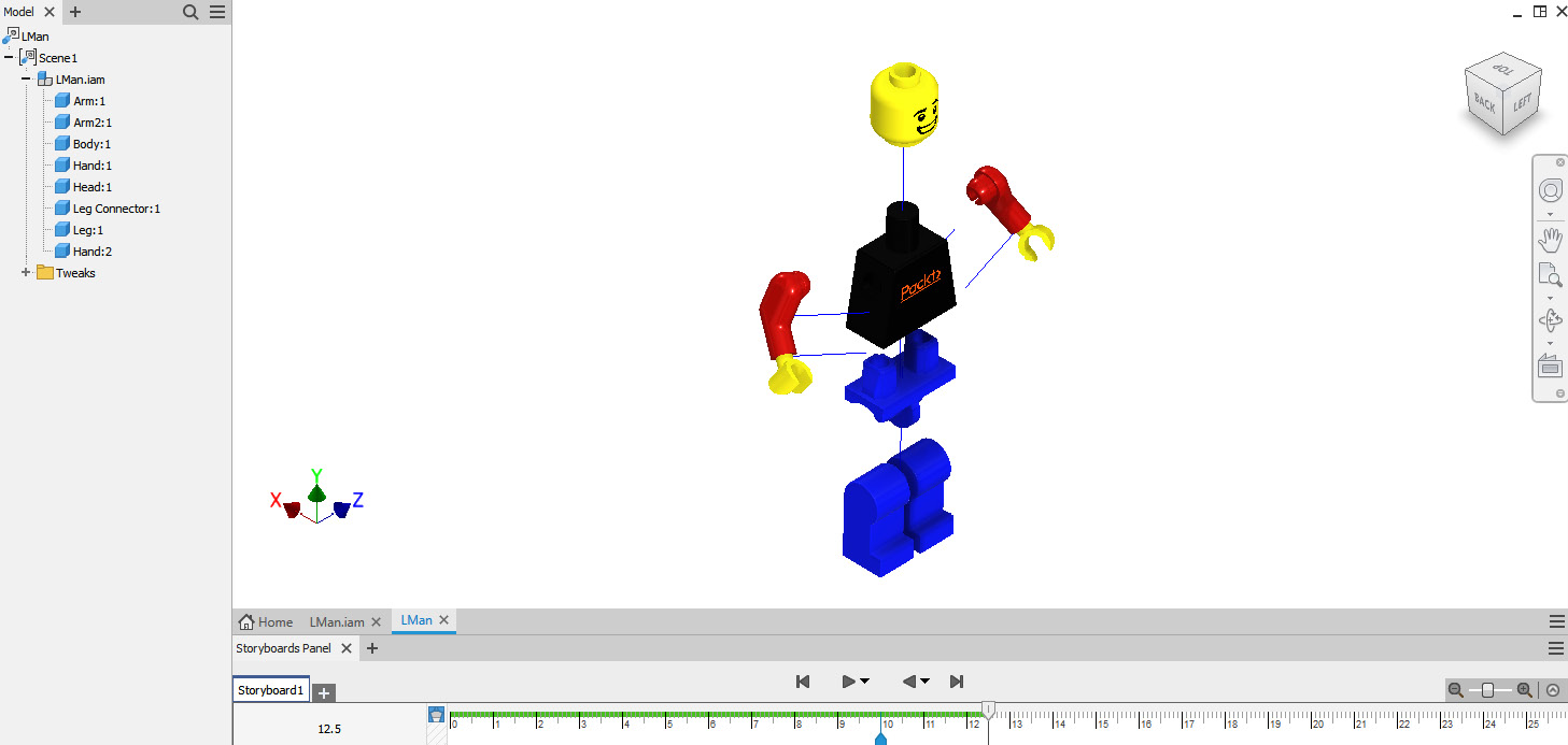
Figure 9.42: Model centered in the Graphics window
- Navigate to and select the View tab. Choose Orthographic and select Perspective.
- Select Shadows as Active. Then, select the drop-down menu and untick the Ground Shadows option.
- Select Visual Style, and then choose Realistic.
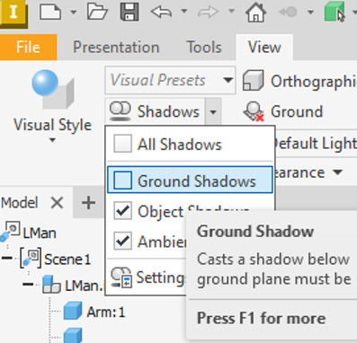
Figure 9.43: Visual display options to change
- Currently, a white background is visible; this can be changed if desired. Select the Tools tab in the ribbon.
- First, select Application Options and then Colors.
- Within the Colors options, set In-canvas Color Scheme to Light, and select Background as Gradient, as shown in Figure 9.44.

Figure 9.44: Background color changes
- Click on Apply, followed by Close.
- Select the Presentation tab in the ribbon. Select Publish to Video.
- In the Publish to Video window, select Current Storyboard. Select and change Video Resolution to 1920 x 1080 (16:9). Browse the location to save the video in the Chapter 9 folder.

Figure 9.45: The Publish to Video options
Change File Format to .avi. Select OK. Then, select Uncompressed as the compressor. Select OK to continue. The video will begin to publish.
- Open the Storyboard1.avi file from the Chapter 9 folder. Play the file. The video will play and show the model exploding into separate parts.
- Drawing views can also be created from a presentation file. To do that, first, navigate back to the LMan.ipn file in Inventor.
- Select 4.7 seconds on the timeline so that the model is fully exploded at this point. Select New Snapshot View from the ribbon.
- The new snapshot view is populated on the right of the screen. Right-click this and select Create Drawing View.
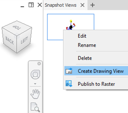
Figure 9.46: Create Drawing View from the snapshot
- Select ISO.idw from the options. Then, select Create.
- Change Scale to 3 : 1, and Style to Shaded. Then, select OK.
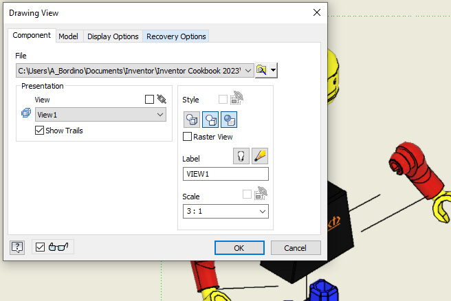
Figure 9.47: Scale and Style changed
- The snapshot view created in the presentation file is placed into the ISO.idw drawing.
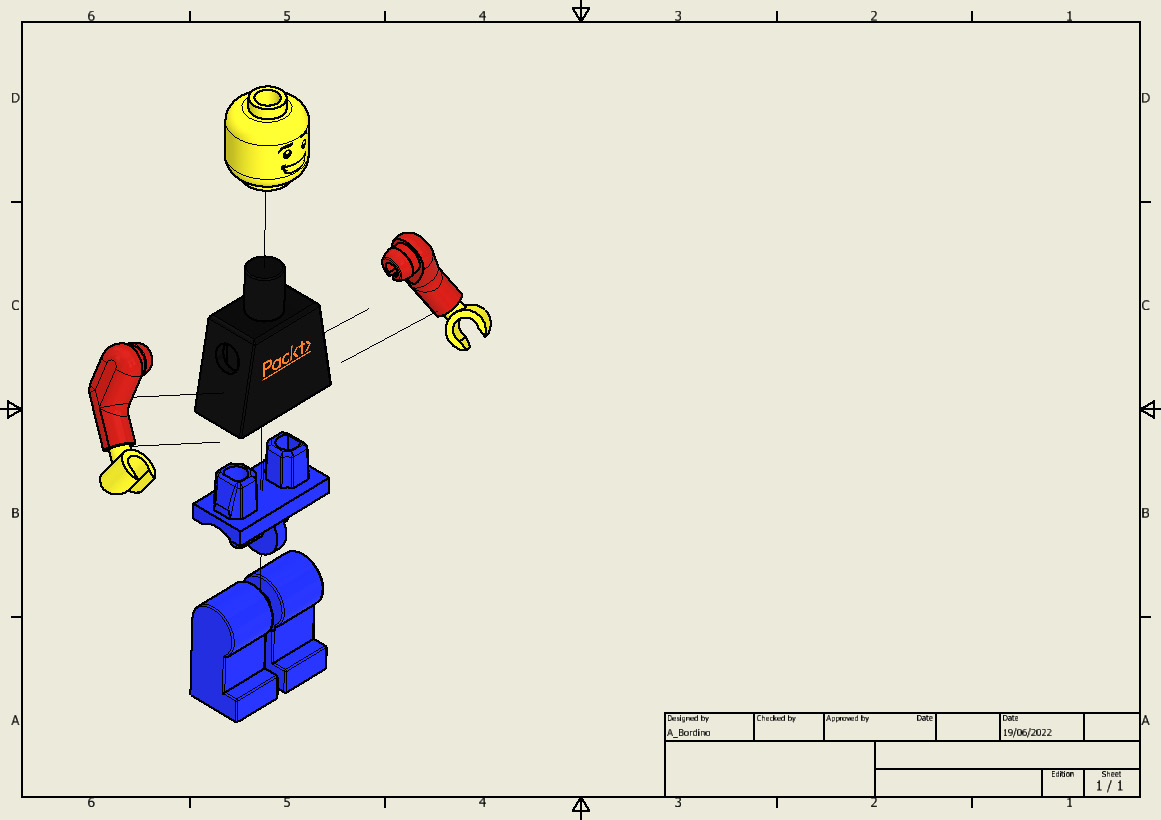
Figure 9.48: The snapshot view from the presentation file placed on the drawing sheet
A presentation file of an existing assembly has been successfully completed, showing a product exploding into its separate parts. The output has been generated as a video, and an exploded view of this has been placed on a separate drawing sheet.
Creating and adding decals and custom materials
Decals of company logos or other images are sometimes required to be featured on a CAD model. In this recipe, we will place a logo decal onto a model, placing it on various geometry types, including curved features. We will also specify and create a custom material for the model and save this in the material and appearance libraries (custom appearances can also be created in the same way).
Getting ready
To begin this recipe, you will need access to the Bearing Bracket.ipt file. Select the Inventor 2023 Cookbook folder and then select the Chapter 9 folder to find the part file.
How to do it…
To begin, we will start to create the custom material, define its properties, and also show how it will display in the model:
- Ensure that you have Bearing Bracket.ipt open in Inventor.
- Navigate to the Quick Access toolbar, and you will notice that the active material at present is Iron Cast. Select the Material Browser command.
Figure 9.49: The Material Browser command
- In Material Browser, select Create a New Material.
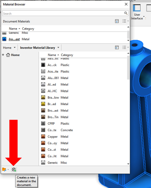
Figure 9.50: Create a New Material
- Material Editor is now open. Now, we can define the properties and physical attributes of our material as well as how the appearance will appear in the model. You do not have to enter all fields; you can just change the name of the material to Steel 101 and set Description as A Generic Steel.
- For Type, select Metal from the drop-down menu. For Keywords, enter Steel and 101.
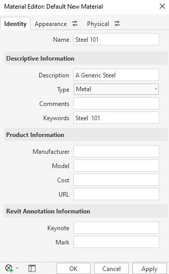
Figure 9.51: Identity fields to enter
- Select the Appearance tab in Material Editor. Select RGB 80 80 80. Then, select the light gray option and select OK.

Figure 9.52: Light gray RGB selected
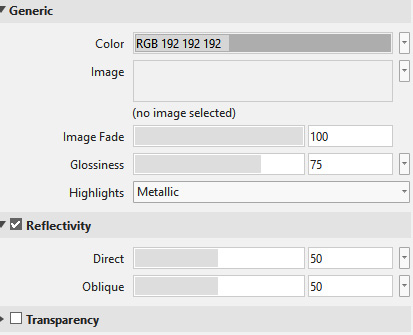
Figure: 9.53: The Glossiness, Highlights, and Reflectivity options to change
- Tick the Reflectivity checkbox.
- Select the Physical tab. Here, you can define the material-specific information for the Mechanical, Thermal, and Strength properties. In this instance, leave these as default.
- The Steel 101 custom material is now visible to select and apply in Material Browser. Select Bearing Bracket from Model Browser. Right-click on Steel 101 in Material Browser and select Assign to Selection. The custom material is added to the part.

Figure 9.54: Steel 101 is assigned to Bearing Bracket.ipt
- Close Material Browser.
- We will now add two decals to the model. The first will be to a flat face, and the second we will wrap around curved geometry. Select the face of the model shown in Figure 4.55 and select Create Sketch.
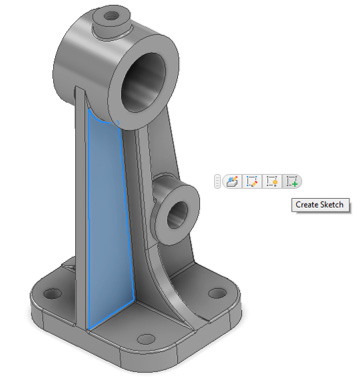
Figure 9.55: Create a sketch on this face
- In the Sketch environment, select Image from the Insert panel in the ribbon.
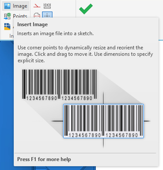
Figure 9.56: The Insert Image command
- Browse the Chapter 9 folder, and locate and select Packt-Logo.png. This has already been created for you and has a transparent background. Select Open.

Figure 9.57: Packt-Logo selection
- Left-click to place Packt-Logo.png on the face.

Figure 9.58: Packt-Logo.png placed on the face of the model
- The logo now needs to be orientated and scaled correctly. This can either be done by clicking and dragging the bounding box of the image in the Graphics window, or by using the Move, Copy, or Rotate commands in the Modify section of the ribbon.

Figure 9.59: The Move, Copy, and Rotate commands
Scale and orientate the image using the methods outlined in step 17 so that it resembles Figure 4.60.
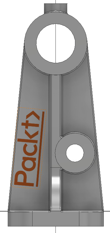
Figure 9.60: The image correctly orientated and scaled
- Select Finish Sketch. We will now convert this into a decal.
- Select the 3D Model tab and then Decal.

Figure 9.61: The Decal command
- The image should be selected by default. Select the face as shown in Figure 4.62 as the face to wrap the decal.
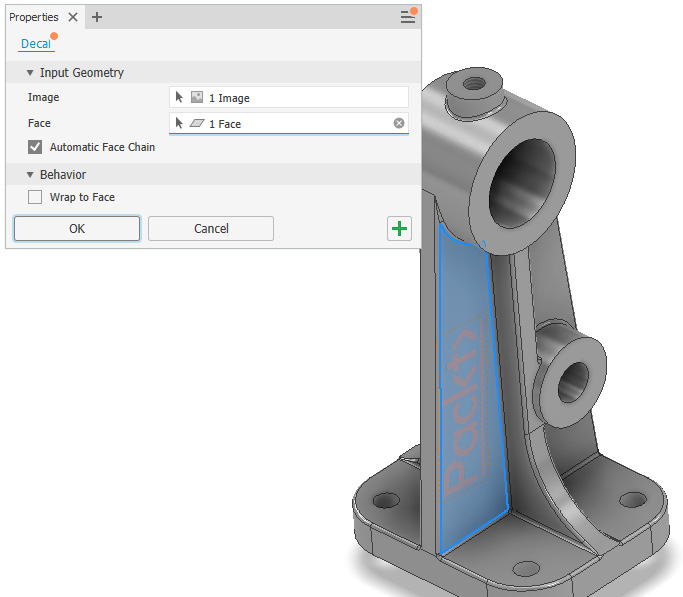
Figure 9.62: The image converted to a decal
- Select OK to complete. The decal is completed and is also visible in Model Browser as an editable item.
- Now, we will create a decal that’s wrapped around a curved face. Select Plane, then, Tangent to Surface Parallel to Plane. For the Plane references, select the curved face highlighted in Figure 4.63, followed by the XYP plane, and create a plane as shown in Figure 4.63 – that is, tangent to the curved surface highlighted.
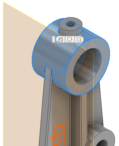
Figure 9.63: Tangent to Surface Parallel to Plane on the surface highlighted
- The image must first be placed on a flat plane before being wrapped to a curved geometry surface. Create a new sketch on the new workplane.
- Place an instance of Packt-Logo.png on the sketch. Orient and scale the image so that it resembles Figure 4.64.
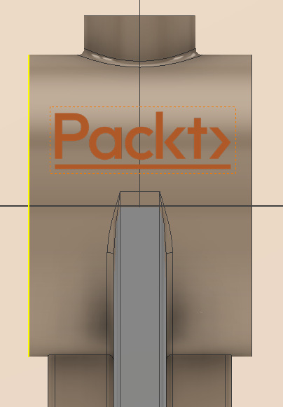
Figure 9.64: Packt-Logo.png placed on the new sketch on the newly created Tangent to Surface Parallel to Plane workplane
- Select Finish Sketch.
- Select the 3D Model tab, and then select Decal. Select the curved face shown in Figure 4.65. Then, select the checkbox next to Wrap to Face. Select OK.
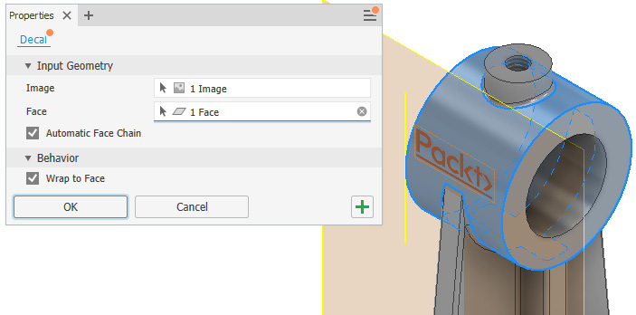
Figure 9.65: The image converted to a decal and wrapped to the face
- The decal is successfully wrapped to the curved face of the geometry.

Figure 9.66: The decal wrapped to the curved face of the model
In this recipe, you have created a custom material with a unique appearance, applied this to the model, and created and applied decals to various types of geometry faces.
Model credits
The model credits for this chapter are as follows:
- Drone Mini (by MBardan): https://grabcad.com/library/drone-mini-2
- Lego Man (by Safira A): https://grabcad.com/library/lego-man-49/details?folder_id=10688431
- 3D CAD Basic exercise/Bearing bracket/Autodesk Inventor Pro (by Alejandra Cervantes Tetrika México): https://grabcad.com/library/3d-cad-basic-exercise-bearing-bracket-autodesk-inventor-pro-1