
7
Moving Forward with Circuit Design Using ESP32
In this chapter, we will delve deeper into designing circuits using alternative microcontrollers. These are circuit boards that aren’t specifically “sewable,” but we can use them for wearables. Using ESP32 will add more interactivity to our sewable circuits. It’s a powerful and adaptive microcontroller board. Although the ESP32 development board form factor is not typically made for a wearable project, we’ll look at how we can add them and why this is beneficial. Using these techniques, you can adapt other microcontroller boards and components to your future wearable projects too. We will learn to program these boards using Arduino software.
In this chapter, we will learn about the ESP32 board. We will prepare the Arduino IDE so we can use it to program the ESP32, and we will write a first sketch. Then, we will advance our knowledge so that we can use it to connect to Wi-Fi. We will then work through several activities, including making a touch-activated wearable as a device for good mental health and wellbeing. This will collect current data from a website through an application programming interface (API).
By the end of this chapter, you will understand why using alternative boards can be beneficial. You will get to know some of the features of an ESP32 board and be able to use it to connect to Wi-Fi. Lastly, through the activities, you’ll understand what an API is, how we connect to one, and how we can update information with it. You will have completed another wearable item too!
In this chapter, we’re going to cover the following main topics:
- Understanding microcontroller boards
- Taking a closer look at the ESP32 board
- Connecting to Wi-Fi
- Creating a map for far away friends and family: for mental health and wellbeing
- Using an application programming interface (API) for live data
Technical requirements
This chapter involves creating a wearable that will connect to the internet and you’ll need the following to complete the circuit:
- Arduino Software as the IDE
- Access to Weather API – create an account at https://openweathermap.org/
- An ESP32 board: Adafruit Feather HUZZAH ESP32
- An OLED display
- Conductive fabrics and conductive thread
Now that we know what this chapter involves, we can start learning about microcontroller boards.
Understanding microcontroller boards
A microcontroller is generally regarded as a simple processor that does a specific task. Sometimes they are referred to as microcontroller units (MCUs). The microcontroller is the brain of our project. They are small, very versatile as we’ve already seen, and usually inexpensive. Microcontrollers also allow a wide range of people with varying skillsets to program and control them, from complete novices to experts. Often, they are used for doing one job repeatedly. The name consists of “micro” because they are small and “controller” because they offer control functions. They are controllers for the physical world, sensing our actions and then using that information to have a reaction.
As we’ve seen before, they have inputs and outputs that are pins or metal sew tabs. We attach our components to those pins and the microcontroller will allow us to control them. So far we’ve mostly been using ATMEL microcontrollers. The ATMEGA328 is the processor on the Arduino Uno board. Also, the Circuit Playground Classic we’ve used contains the ATmega32u4 as its device core.
Development boards have a chip, which is the processor, a power circuit, a hardware connector for programming, and indicator LEDs. Most have a reset button too. The microcontroller Integrated Circuit (IC) has the following:
- A processor
- Memory (volatile, which is temporarily lost when the board is reset, and nonvolatile, where the memory stays even when the power is off)
- I/O peripherals
A development board integrated with a microchip is shown in Figure 7.1 (an Arduino Uno). A microcontroller generally has a low clock speed – it’s not complex in the tasks it can perform, has no operating system, low power consumption, small internal memory, several I/O pins, and is low cost.
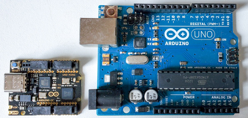
Figure 7.1 – An Arduino Uno microcontroller, the anniversary edition (left), and the R3
To understand the difference between microcontroller and microprocessor boards, we can look at the Raspberry Pi. The Pi can have an operating system, Linux, running on it and you can use a keyboard and display with it as if it were a computer. It is a microprocessor but also a device known as a single-board computer.
The Gemma M0 board that we have used was initially made using an ATMEL ATtiny85 but that was changed to an ATSAMD21E18 32-bit Cortex M0+ chip. This has a 48 MHz 32-bit processor, which is six times as fast as the previous ATtiny85 version.
The Arduino IDE supports more than 1,000 official and non-official boards, so that will give you some context as to how many boards are available for our use. To have a look at some of this huge selection, you can browse online to see the boards that are Arduino compatible. Look to the end of the chapter for links to online shops where these are available.
We will be focusing on the ESP32 chip for this chapter. As we’ll see, it is embedded into many different packages and board styles. Let’s take a closer look.
Taking a closer look at the ESP32
The ESP32 is a single 2.4 GHz Wi-Fi and Bluetooth system on a chip (SoC) and a general-purpose microcontroller, designed by Espressif Systems. You can find more information online about their processors at https://www.espressif.com/.

Figure 7.2 – Varieties of ESP32 dev boards
This chip has been added to different boards (Figure 7.2) and it is these development boards that we’ll be using. The prices for these boards vary. Consider what the features are for the different boards and the cost trade-offs. ESP32 offers capacitive touch, I2C, SPI, PWM, and much more.
A guide accessed online at https://lastminuteengineers.com/esp32-pinout-reference/ contains the common pinouts (GPIOs) for the ESP32-based boards.
Important to Note
Although these are the common standard pin layouts, I would highly advise you to always check your specific board for the GPIOs. Some boards have 30 pins, others 36. You don’t want to connect something incorrectly and waste a lot of time trying to fix what is a simple error.
The ESP32 chip is designed for many types of circuits, including mobile, wearable, and Internet of Things (IoT) applications. It has capabilities that make these projects possible, including Wi-Fi and Bluetooth capabilities. You can buy it in chip form or as a development module (dev), which is what we’ll be using.
For the most up-to-date information, there are documents on the Espressif website https://docs.espressif.com/projects/arduino-esp32/en/latest/getting_started.html for reading about developments and different guides to get started. Currently, the ESP32 family is divided into these main categories:
- ESP32 – Wi-Fi and BLE
- ESP32-S – Wi-Fi only
- ESP32-C – Wi-Fi and BLE 5
The ESP32 is an upgrade from an earlier chip, the ESP8266, which was very popular when it was released. It allowed makers, developers, and hobbyists to integrate Wi-Fi into their designs at a far lower cost than what was possible before that point in time. Typically, people would purchase a large shield (Figure 7.3) that was placed on top of an Arduino Uno, so the ESP8266 also allowed much smaller prototyping.
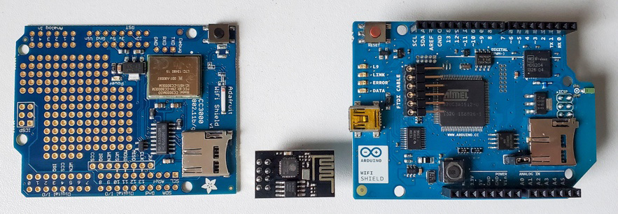
Figure 7.3 – Wi-Fi shields and the ESP8266 (the small one in the center)
The ESP32 has more pins, analog in and out, and two cores with a higher-speed processor. As a result, many makers and developers have switched to the ESP32. DFRobot makes a series of ESP32 boards, https://www.dfrobot.com/ called FireBeetle, which come with no headers soldered so that you can use them for a variety of projects. They are reasonably priced, allowing low-cost prototyping with an ESP32-based board. They also have a Beetle that is sewable and is only 35 x 34 mm in size, as shown in Figure 7.4.
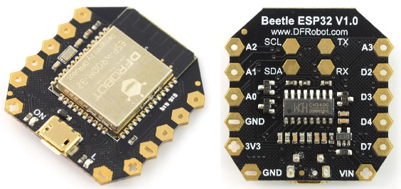
Figure 7.4 – A DFRobot Beetle ESP32, front and back
For this chapter, we will be using the Adafruit Feather HUZZAH ESP32 (Feather), which came out in May 2017. Note that there is also an updated version of this board, which is the Adafruit ESP32 Feather V2 - 8MB Flash + 2 MB PSRAM. There are several reasons why I’ve chosen the Feather board. For a start, it has a reset button, not the typical reset and boot button. For many (indeed, most) of the ESP32 development boards, you need to press the boot button to upload your code. On the Feather board, you don’t have to do this. It also has a connector for a battery, which is great for our wearable projects. The final reason is that it is breadboard friendly – most of the other dev boards do not fit onto a breadboard conventionally and you need to arrange it across two boards. You can get it in a soldered version, with pins or stackable headers, or one that isn’t pre-soldered.
The Feather board has a dual-core ESP32 chip (Arduino sketches run on one core by default, but we can create tasks to use both cores), with 4 MB of SPI Flash memory, as well as Wi-Fi and Bluetooth, so there are plenty of options for our wearable projects.
Also, there are over 50 wings that can be used with this board. A wing is like a shield or a hat that goes on the Feather board that you are using. This gives it extra capabilities, such as adding an OLED screen easily, for example. They should all be compatible so you can swap out the main board or extra boards without any problems.
Lastly, it’s worth mentioning a tiny board, the QT Py ESP32-S2, introduced in December 2021, with the ESP32-S2 chip on it. In Figure 7.2, this is the first board on the left, so you can see the size comparison. It has fewer available pins and only uses one of the two available cores for processing.
Let’s get started with how we can use and program an ESP32 board. You’ll need to follow this next section to use your ESP32 board, regardless of which board you are using.
Activity 7.1 – Programming the ESP32, libraries, and tweaks for Arduino
Now that we know more about the ESP32 boards, we need to do a few things to be able to use them with the Arduino IDE. The ESP32 Arduino board support package is currently part of the 2.0.0 or later release, so you may want to check whether your version of Arduino already has this package installed. If not, then you’ll need to follow along in this section. The board information is also online at https://github.com/espressif/arduino-esp32#using-through-arduino-ide.
To use versions of an ESP32 dev board with the Arduino IDE, we need to add the ESP32 boards. There are two things we need to do to add them. You won’t need to do this again unless you delete Arduino or install it on another computer, for example.
Modifying preferences
With the Arduino IDE opened, go to the Preferences window, which is File | Preferences, or use Ctrl + Comma (PC) or CMD + Comma (mac) on your keyboard. If you look near the bottom of this window, there is an Additional boards manager URLs: field, with a field that is empty. If you already have a URL there, (it’s likely you already have the Adafruit boards package), then add a comma and paste the URL, which adds a stable release of ESP32 boards to the Arduino IDE. There is also a development release link online (https://raw.githubusercontent.com/espressif/arduino-esp32/gh-pages/package_esp32_index.json).
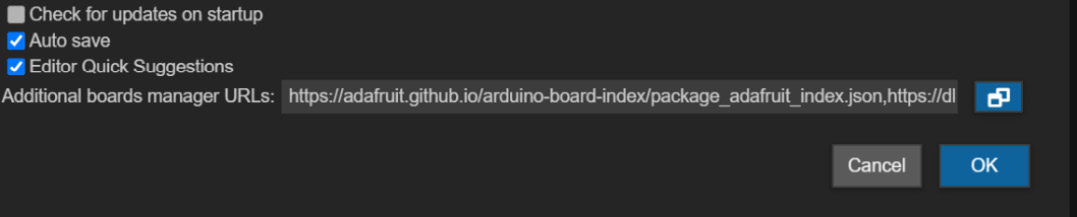
Figure 7.5 – Additional Boards Manager URLs
See Figure 7.5, which shows the preferences view with the URL field for where the URL should be added. Click OK when you have added the board.
Using the Boards Manager
Now, you need to go to the Boards Manager. You can get to it by clicking the second icon down on the left, which looks like an Arduino board. You can also go to the Boards Manager by going to Tools | Board | Boards Manager. Search for ESP32 (it will be by Espressif Systems) and click Install. The boards should now be installed. Figure 7.6 shows a new menu item, esp32.
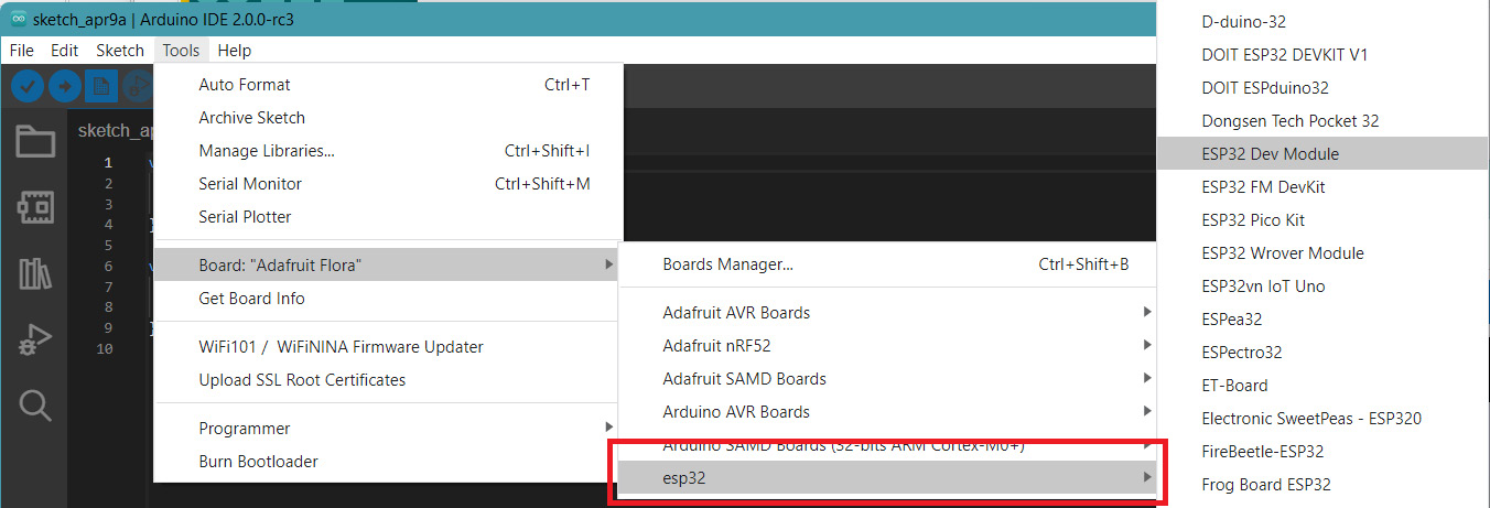
Figure 7.6 – ESP32 boards are now available in the Board menu
We will be using the Feather ESP32 version, so look for Adafruit ESP32 Feather in the list of boards under the esp32 section. There will now also be example code that we can access to try new things on this board.
We will be going through Wi-Fi technologies with the ESP32, so there will be a few activities to follow. These include the following:
- Establish a connection with the Feather Huzzah ESP32, uploading an example sketch
- Make tweaks to code if using different ESP32 boards
- Connect to Wi-Fi, scan networks near us, connect to our own network
- Apply this new knowledge to a project
Now that we know what’s coming up, let’s get started with the first activity, connecting and communicating between our ESP32 board and computer. Let’s get an LED to blink and upload our first sketch on the Feather!
Activity 7.2 – Hello World, does it blink?
This will be a quick activity but it’s very important! We need to establish a connection between our ESP32 board and computer. When your board is plugged in, first check that the board and port are both correctly selected (in the Tools menu).
Once you have the correct board and port selected, open the Blink example that we used earlier when we installed Arduino. It’s in the File | Examples | Basics folder. Upload the code to your Feather (Figure 7.7).
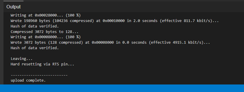
Figure 7.7 – Code successfully uploaded
It’s important to note that this exercise is for the Adafruit Feather Huzzah ESP32 board. When we upload the code, we will see the upload process and associated messages in the output window. Some boards will behave differently and have other messages.
Using a different ESP32 board
If you are using a generic ESP32 or just another ESP32-based board, you might have to also follow this advice. If you cannot find your board in the menu, I default to choosing ESP32 Dev Module, as that seems to work most of the time when uploading.
Important to Note for ESP32 Boards
If you are using other ESP32 boards, then you might have to hold down the BOOT button on your board (Figure 7.8). In the output window, it will display Connecting........_____.....___ when you see that message – press (then release) the BOOT button. The display window should then show a message similar to Writing at 0x0000e000... (100 %).
If you don’t hold down the BOOT button, you will see a message similar to the following in the output window:
A fatal error occurred: Failed to connect to ESP32: Timed out waiting for packet header
Upload error: Failed uploading: uploading error: exit status 2
We won’t get this message with the Feather Huzzah boards as they are made so that they will enter this boot mode for programming. This is actually a great feature.
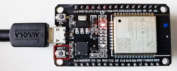
Figure 7.8 – The boot button on other ESP32 boards
The default code in the Blink sketch will also need a little tweaking. It is likely that it won’t recognize the BUILTIN_LED variable that is used. So, we’ll edit the code to select pin 2 to get our LED to flash. Modify the blink code. Create a const int ledPin = 2 variable and use that variable to replicate the blink action. The code is the following:
const int ledPin = 2;
void setup() {
  pinMode(ledPin, OUTPUT);
}
void loop() {
  digitalWrite(ledPin, HIGH);
  delay(1000);
  digitalWrite(ledPin, LOW);
  delay(1000);
}
That should work for versions of the ESP32-based board. You should now have a blinking LED (likely blue) on your board. Well done, this is the first step to getting to know a very exciting and versatile board. Now, let’s look at one of the exciting features that make the ESP32 board stand out from the others – Wi-Fi. Let’s get connected!
Connecting to Wi-Fi
One of the main features of using an ESP32-based board is the Wi-Fi functionality. Let’s jump straight in and learn how to connect to Wi-Fi so that we can get more out of our board. We can also use over-the-air (OTA) updates for this board. If our ESP32 board is installed somewhere that’s not easily accessible, we can program it through Wi-Fi. This does require installer code (this code must be in all your uploaded sketches to that board for it to continue working) to be on the board first before it can be used this way; it’s a good feature.
Activity 7.3 – Let’s get connected
There are a few examples we can use for connecting to Wi-Fi. We will look at these examples so that you can start to see the potential of using an ESP32 board for your wearable projects. We will look at the following:
- Scanning to see the networks near us
- Connecting to your Wi-Fi network
Let’s start by scanning for networks around us so that we know our board is working and able to see internet connections.
Scanning to see the networks near us
One of the main reasons we are looking at ESP32-based boards is because we can use them for Wi-Fi. Let’s open some code to use our Feather board to display the list of available Wi-Fi networks where we are. There is an example file that we will use. Go to File | Examples | Wifi | WiFiScan and upload it to your board. The Wi-Fi library is one that should be installed when you installed Arduino, but if you can’t see this example sketch, check whether you have the Wi-Fi library.
One thing to point out is that we typically use faster communication methods with an ESP32 board. You’ll notice a line of code in the sketch defines the serial speed of 115200. Don’t forget to change the speed in the Serial Monitor through the drop-down menu. If you don’t, you will see foreign characters in the window that look like errors.
When you open the Serial Monitor, you’ll see a scan (Figure 7.9). It will list the number of networks found and their names. Hopefully, your local network will be there as well.
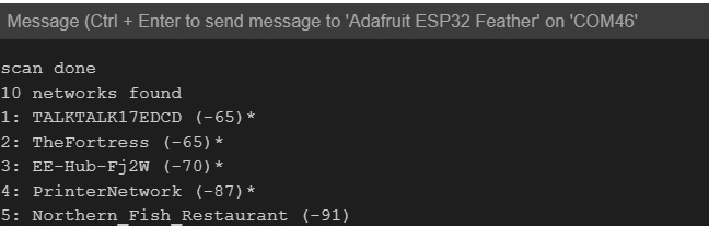
Figure 7.9 – Scanning for Wi-Fi networks
Now that we can see that our ESP32 board has found the networks, let’s connect to one of them.
Connecting to your Wi-Fi network
There are several sample files in Arduino that will help us make a connection to our Wi-Fi network. Let’s do the following:
- Open File | Examples | WiFi | SimpleWiFiServer (see Figure 7.10).
- Change two values in the file to start a connection between our Wi-Fi and the ESP32 board: the ssid name and the password input for the network you want to join.
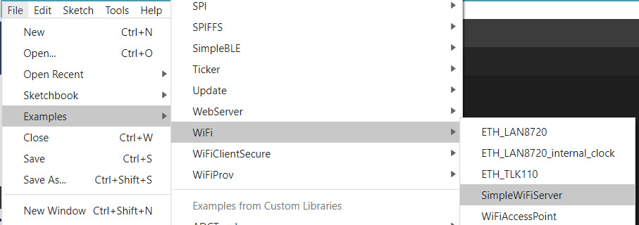
Figure 7.10 – The SimpleWiFiServer file location
Once the file is open, change the values in the following fields to start with:
const char* ssid = "yourssid";
const char* password = "yourpasswd";
- Change these values to your personal network ID and password. After the ssid and password fields have been changed, create your variable for the LED.
- Edit the LED pin number to 13 for Feather ESP32, or 2 for generic ESP32 boards. The LED pin number is located in three places within this code, so we should follow good practice and create a variable for our LED pin.
- Create a variable. Remember variable creation requires a type, a name, and a value. The type is int, the name I’ve chosen is ledPin, and the value is the pin that the LED is on, 13. This would be int ledPin = 13;.
- Find the code with the LED’s current pin number (5). Amend those three locations, remove the number 5, and in its place, put our variable, ledPin, into three lines, the first in setup() and the other two in loop():
if (currentLine.endsWith("GET /H")) {
digitalWrite(ledPin, HIGH);
}
if (currentLine.endsWith("GET /L")) {
digitalWrite(ledPin, LOW);
}
Using a variable can save you a lot of time and potential errors.
A Note about Using a Variable
If we use a variable to define a pin number, instead of changing the pin number in every place throughout the code, it will make it a lot quicker for us to change the pin number or a value in the future. Also, using a variable helps to eliminate errors that can happen if we forget to change one of the pin numbers or values in the code.
- Then, upload your code to your board. Reminder: if you’re using a standard ESP32, you may need to hold down the BOOT button on your ESP32 upload.
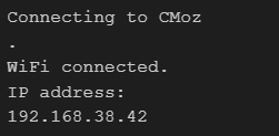
Figure 7.11 – Output to Serial Monitor
- After the code is uploaded, open the Serial Monitor, and you’ll see your board connecting to your network (Figure 7.11). The output monitor will display an IP address. Copy this number so that we can visit it. If it doesn’t appear, press the BOOT button or the RESET button on your board to reset it to load the code.
Important Note
You need your computer and your device to be on the same network to visit the web page that will be generated when we go to the IP address.
- Paste the IP address from the Serial Monitor into a browser. When the page loads, you should have the following (Figure 7.12) page view. This allows us to control the LED on our ESP32 board. Click the links to check whether yours is working correctly. If it isn’t working, check you’ve changed the pin number to the correct pin for your board’s LED. Make sure to also check that you have changed this pin number in three places throughout the code. Lastly, check that the network is working.
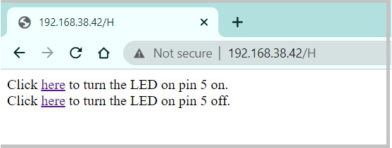
Figure 7.12 – A browser window with the web page connected to the ESP32 open
You’ll notice that this web page says, Click here to turn the LED on pin 5 on. This is because the HTML in our file has this exact text written, so we should also amend that. In the sketch, you’ll see the following line:
client.print("Click <a href="/H">here</a> to turn the LED on pin 5 on.<br>");Amend this line to reflect the correct pin (13) that you used for your board.
Extra challenge!
Spend some time looking through this code and playing around with it. We can see from the code written that appending the URL with /H will turn on an LED as we've done previously in the code using digitalWrite (ledPin, HIGH). You should spend some time playing with the code in small ways, adding an LED, for example, and amending the code to turn that extra LED on or off.
Have a look through the code and the way that it is displayed in the browser and change its appearance too. I have uploaded modified code that will have buttons to click. It has a .h file, which we can store our credentials in so that they are not stored in the main code body. The code is here: https://github.com/cmoz/Ultimate/tree/main/C7/C7_ESP32_LED_On. In Figure 7.13, there is an example of using buttons and controlling two LEDs. You can modify the colors and look of the website too.
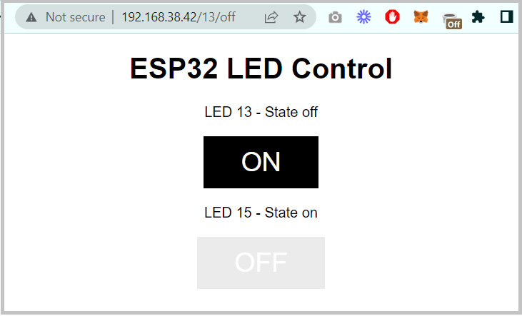
Figure 7.13 – The web interface for the program
Now that we’ve successfully found networks we can connect to and connected to our network, let’s look at a project that addresses how we can add interactivity to a wearable design using the advantages of the Feather.
Creating a map for far away friends and family: for mental health and wellbeing
We will be creating a map reminding us of our faraway friends and family! Sometimes, it can be difficult for families to stay connected. I know I have family far away and I think of them a lot. It’s not always easy to call or speak with them because of the time differences too. Heshmat, Y., & Neustaedter, C. (2021) studied family and friend communication over distance during the pandemic. Their paper (https://dl.acm.org/doi/pdf/10.1145/3461778.3462022) shows the results of design lessons for these times of extreme disconnection.
I realized that I have my family’s time zones that correspond to where they are and what the weather is like on my mobile phone. In a way, it makes me feel closer to them to imagine what the weather or conditions are like for them. Do you have a similar way to form some of these small connections with friends or family that are far away? We will be creating a wearable to remind us of where our loved ones are. The final project is shown in Figure 7.14, a vest with map locations to interact with that display live location data, styled as a pocket watch concept.
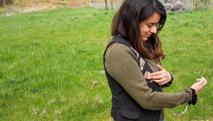
Figure 7.14 – “Touch me” live mapping of friends and family (modeled by Sushmita Joshi)
This project focuses on creating a wearable that could allow us to feel close to missing loved ones. I’m going to make a vest with touchable areas that will display the current weather conditions for where my family members are located.
For this activity, you’ll use the following:
- Adafruit Feather HUZZAH ESP32 (or your own ESP32 board)
- An OLED
- An optional vibration motor
- Conductive material and conductive thread or wires
- An article of clothing that you can upcycle
Once you’ve gathered the required items, think about what connections would make you feel closer to your friends and family, and then let’s start the next activity.
Activity 7.4 – Making your maps using symbols that work for you
To start this activity, I thought that having a map shape to represent where my family members are located would be the first step in order for me to feel closer to or think about them. I went online to find usable shapes to represent where they live and I will cut these shapes out of conductive material. The map is from https://www.worldatlas.com/maps/canada/ontario, where you can get your map too. Figure 7.15 shows where family or friends live.
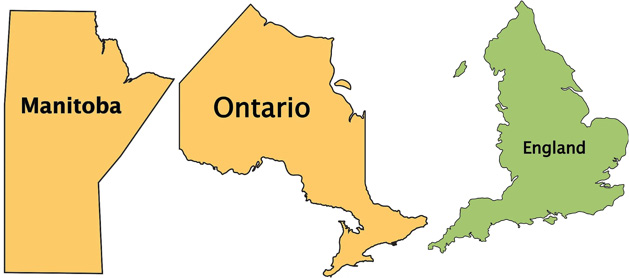
Figure 7.15 – Map shapes
I’ll use these shapes and will cut them out of conductive fabric. I’ll use the ScanNCut machine again but it’s fine to cut shapes and symbols out with scissors. When you’ve decided on your symbols and cut them out, put them aside for now. We’ll look at the touch capacity of the ESP32 next to get this part of our circuit working.
Activity 7.5 – Touch me! Building your touch pads
Let’s create our touch circuit on the Feather. The touch pins on an ESP32 sense variations in electrical charges. These can be generated from our touch, or from items that are conductive, such as conductive fabric. Often people use these touch pins to wake the ESP32 from sleep. The ESP32 has several sleep modes that reduce power consumption. There are five different sleep modes: active, modem, light, deep, and hibernation. We won’t be using these here for this sketch but it is something to consider for your future wearables.
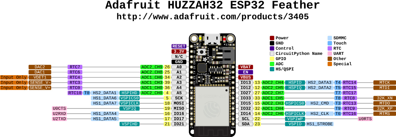
Figure 7.16 – A pinout diagram for Adafruit Huzzah32 ESP32 Feather
To use touch capabilities with the Feather, we read the values of the pins that we define in our code as being touch-sensitive using the touchRead(GPIO) function. There is a possibility of 10 capacitive pins and these allow us to replace a traditional button or other standard inputs. This can reduce the wear on components.
The touch pins defined in the Huzzah32 ESP32 Feather pinout diagram are from Adafruit (Figure 7.16, courtesy of Adafruit https://learn.adafruit.com/assets/111179) and Attribution-ShareAlike Creative Commons (http://creativecommons.org/licenses/by-sa/3.0/).
These touch pins are the same for most ESP32 boards but other boards may have additional touch inputs. Always check the development board that you are using to see which pins have been broken out or made accessible. Have a look at the Feather to see where these pins are located.
All we need for this activity is the board and the USB cable. Plug in the board, select the Feather from the Board menu, and find your port. Open the file, copy the code, and paste it into a new sketch. See the following link: https://github.com/cmoz/Ultimate/tree/main/C7/C7_TouchInterruptESP32.
Let’s look at the code in detail. We start with declaring our variables; this includes the threshold and three bool values. The threshold is how sensitive the touch will be. A lower number is more sensitive. Then, the three bool values define whether a touch is true or false. We initialized these to all be false. This means no touch input:
int threshold = 40;
bool touch1detected = false;
bool touch2detected = false;
bool touch3detected = false;
In our setup() function, we open the Serial Monitor so that we can see the touches registering. We also define what pins we are using for touch input through the touchAttachInterrupt (T5, gotTouch1, threshold) function. This allows us to define the pin and threshold; it will also run a function when a touch is detected:
void setup() {
Serial.begin(115200);
delay(1000);
Serial.println("ESP32 Touch Interrupt Test");
touchAttachInterrupt(T5, gotTouch1, threshold);
touchAttachInterrupt(T3, gotTouch2, threshold);
touchAttachInterrupt(T0, gotTouch3, threshold);
}
In the loop() function, the code is checking for any touches on the pins. It then executes code if a touch has been detected. It will set the bool value back to false and print to the Serial Monitor. You could add some LEDs to turn on here, for example, to test your code and work through the example in further detail:
void loop(){
if(touch1detected){
touch1detected = false;
Serial.println("Touch 1 detected: GPIO 12");
}
if(touch2detected){
touch2detected = false;
Serial.println("Touch 2 detected : GPIO 15");
}
if(touch3detected){
touch3detected = false;
Serial.println("Touch 3 detected: GPIO 4");
}
}
After the loop() function, we have the three functions that will change the bool value to true when there is a touch. This will then trigger the touch detected in loop():
void gotTouch1(){
touch1detected = true;
}
void gotTouch2(){
touch2detected = true;
}
void gotTouch3(){
touch3detected = true;
}
Open the Serial Monitor and you should have a functional readout of the touches when you touch the pins on your Feather or other ESP32 board.
Experiment a little with the code: display other messages or use other pins for touch. Maybe add an extra pin or two and get that working.
Once you’ve had a chance to expand the code a little, we will add an OLED to our circuit. This will be used to display information.
Activity 7.6 – Adding an OLED for displaying information
We will add an OLED to our circuit to initially display the touches registered. Then, we will move on to a more complicated and interesting feature of our wearable, displaying the weather data from our conductive map pieces. Here are the necessary steps for this activity:
- First, let’s hook up the OLED. As previously, we only need to use the I2C wires, SDA and SCL, as well as the ground and power. The I2C pins on the Feather are marked with SDA and SCL, and they are located near the top end of the board where the antenna is. Other ESP32 boards have SCK/SCL on pin 22 and SDA on pin 21.
Once connected, we should run sample code to test whether the OLED is working and connected correctly. You’ll notice now that we’ve done several activities that we often follow a similar procedure. We connect one type of input or output and then we run a small sample sketch to check whether things are working. This is usually the best way to work, as it is a lot easier to solve problems when the components are isolated.
- With the OLED connected to the Feather, open the example code in File | Examples | Adafruit SSD1306 | ssd1306_128x64_i2c (Figure 7.17):
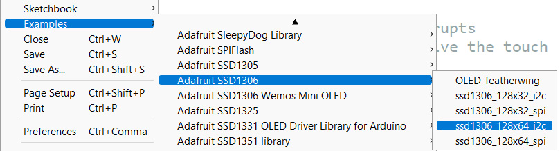
Figure 7.17 – Open the example sketch
- Upload the code to your board. You should see the OLED displaying all the sample graphics that are included in this sketch. If yours isn’t displaying any graphics, then check that you have supplied ground and power to your OLED from the Feather. Ensure to also check that your SDA and SCL pins are the correct way around. Lastly, check that all your wires/connections are secure and not loose.
- Now that we know the connection works, let’s merge our code with the sketch that registered touch inputs in the previous activity. Open that sketch again and we’ll combine both working sketches together. Try this yourself first. If you do it step by step, it is a good way to understand what the code is doing:
- Begin by adding the libraries that the OLED uses at the top of the sketch.
- Then, work towards the setup() function where there is an initialization of what we are using.
- Follow with the behavior that you want the code to execute. We want the OLED to display which touch is registered, so where do we add that code and what should it say?
To check your code, visit GitHub online to view and download my completed version if you’d like to check it against mine, at the following link: https://github.com/cmoz/Ultimate/tree/main/C7/C7_TouchInterruptESP32_OLED.
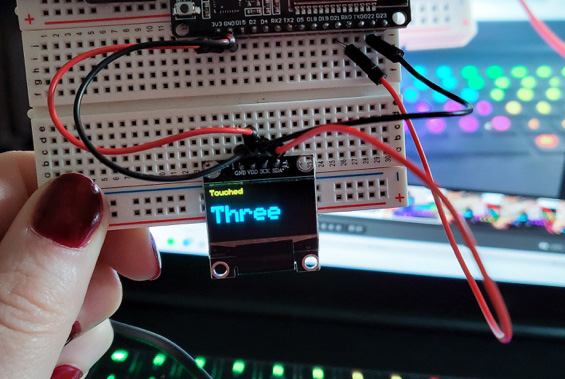
Figure 7.18 – OLED and ESP32 connected with the touch code
Now that we have our OLED displaying the touch information (Figure 7.18), we can get it to display something far more interesting – the weather data for our chosen locations. To achieve this, we will learn how to use an API to connect to services.
Using an Application Programming Interface (API) for live data
An API allows two computers to talk to each other. When you check the weather or access services, you’re using an API. In a sense, it’s a messenger; it sends a message to a service, such as the weather service, saying that you are requesting data and what the data that you’re requesting is, and then it is returned to you. The API key is the code that gets sent to identify who you are (whether a user or a developer) and it sends the requested information to you if the key is correct. This often is based on the type of account you hold with the API provider.
We’ll be setting up a free account to access an API for weather data. This next activity will take us through the process step by step.
Activity 7.7 – Connecting to an API
In this activity, we’ll use the ESP32 to request the weather data relevant to our specific predetermined locations, using an API for live data. We will use a service provided by https://openweathermap.org/ to access the information that they have about the weather. To start, we need to make an account with them (Figure 7.19). Once we make our account, we can generate an API key that is needed to connect the requested data.
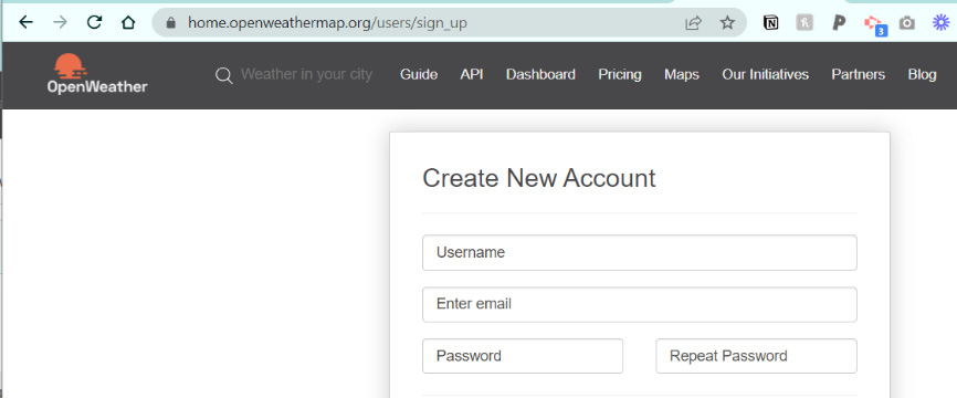
Figure 7.19 – Create an account
To create an account, you’ll need to enter a username, email, and password. We only need to access the free service at this point, but in the future, if you use them for more API calls or other services, you may need or want to upgrade your account.
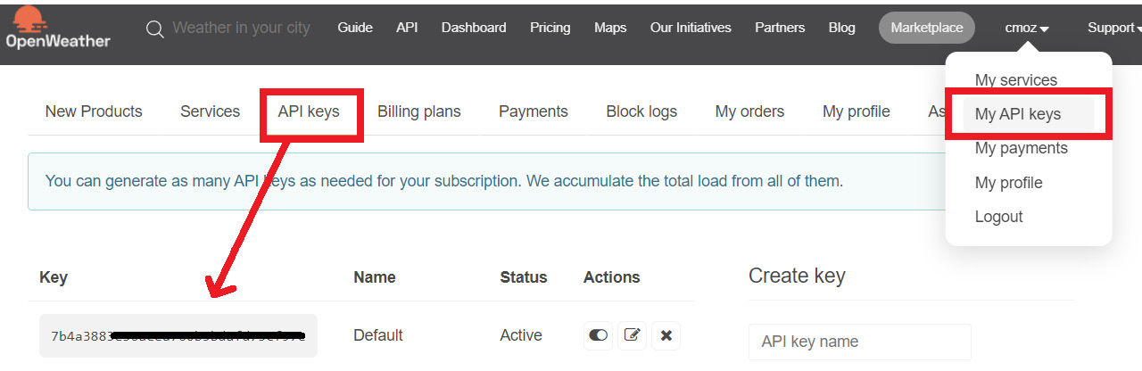
Figure 7.20 – Your API keys
After your account is created, do the following:
- Navigate to the My API keys section (Figure 7.20) in your account. It should look similar to mine.
- I’ve generated a new key called current weather, but the default API key works fine.
- Copy your API key. Note that if you have just created a new key, it can take 10 minutes or so to be ready for use.
Check that it’s ready to use by sending a call to your browser using http://api.openweathermap.org/data/2.5/weather?q=Toronto&APPID=yourAPIkey. Change yourAPIkey to the key in your account. If it’s working, you’ll have output similar to Figure 7.21 with weather information from the city selected.
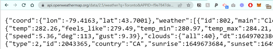
Figure 7.21 – The API call comes back if it has worked
Now that we are connected, we will access a current weather call. Details on this part of the API can be read at https://openweathermap.org/current, which details what we will be doing.
If you skim through to the API call section, you’ll see (Figure 7.22) how to form the call to request the information.
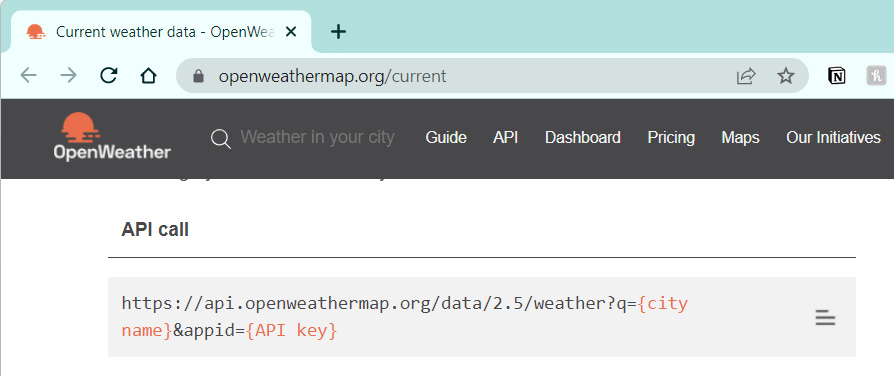
Figure 7.22 – OpenWeather API forming the API call
One of the calls is for the URL appended with the city we are requesting and our API key. For this, we use the following:
https://api.openweathermap.org/data/2.5/weather?q={city name}&appid={API key}We’ll start by checking whether the simplest form of this code works with our Feather and that we can retrieve a basic weather call:
- The code at https://github.com/cmoz/Ultimate/tree/main/C7/C7_API_testCall demos access to the full API. You’ll need to fill in your API key, your SSID, and password.
- Upload the code to your ESP32.
- Open the Serial Monitor. There should be a request for the information through the API call that we wrote.
Now that we have a working API call, a working OLED, and the ESP32 with several bits of implemented code functions, we will bring it together. This is exactly what’s covered in the next activity.
Activity 7.8 – Connecting all the parts
Well done for making it this far already. We’ve covered a lot of ground! You’ve gotten the ESP32 board working with code to connect to Wi-Fi, you’ve gotten input touches to register touch, and you have also hooked up an OLED to display when touches have been detected. You have also connected to an API to access live data. Now, we will add all of these working parts together to continue creating our map for faraway friends and family.
This is our biggest task to date but don’t let that worry you. We will go through it step by step and there is no rush to finish in a hurry. Take the time you need to process and work through the information, as it’s a fun and rewarding project when you get to the finish. It also teaches you a lot of new and exciting concepts that you will take forward in your wearable technology journey.
To complete this activity, we will need access to the completed code and all of our components to make the physical circuit.
The items are as follows:
- Completed code: https://github.com/cmoz/Ultimate/tree/main/C7/C7_WeatherAPI
- An ESP32 board
- Conductive fabric pieces
- Conductive thread/wires
- An OLED (I’m using a yellow/blue style OLED)
There are a few steps to follow for completing this activity, but first, let’s look at the ways we can make a typical development board wearable.
Some of the development boards come with pins, called header pins. We can use needle-nose pliers to gently bend these pins back so that they are flatter, rather than pointing straight down (Figure 7.23).
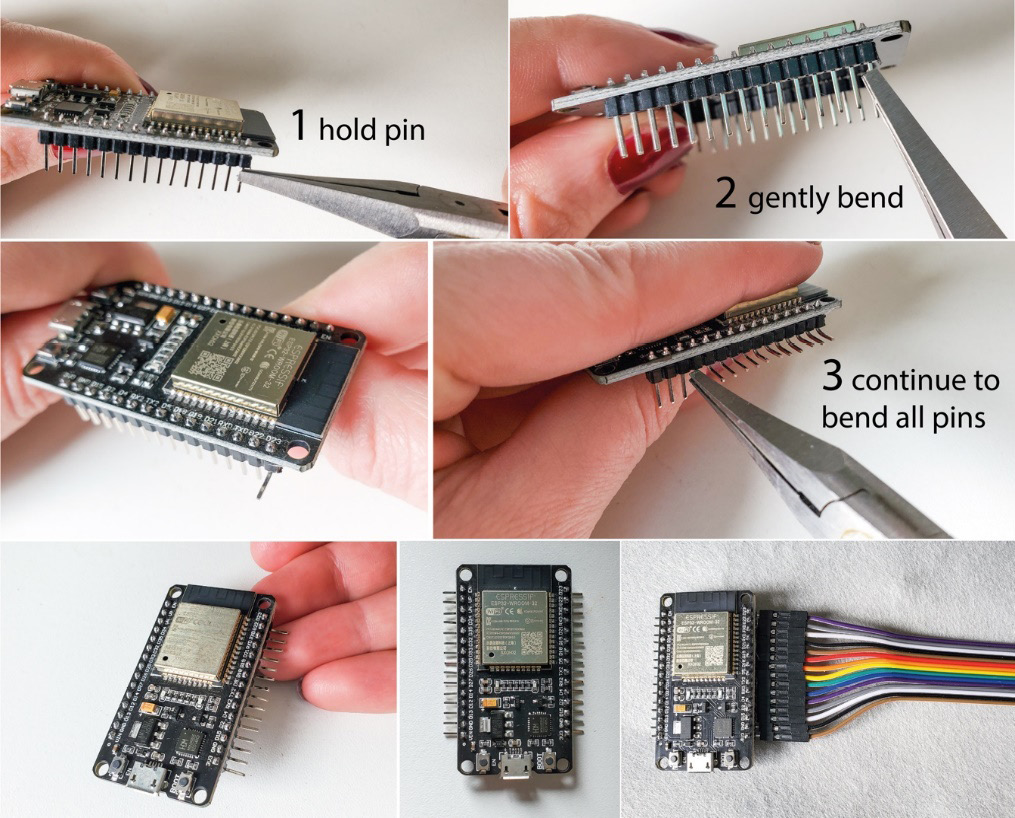
Figure 7.23 – Making a microcontroller board wearable
Once the pins are flat, we can place the board on a piece of fabric, such as felt. We can then sew these connections using multiple stitches over each pin. Alternatively, you can attach a DuPont cable with a socket end to these pins and sew it into place with thread. Both methods are appropriate, depending on your wearable placement and the durability needed.
We can use these techniques for other types of circuit boards. This way, it opens up the range and diversity of types of boards with varying features that we can use in our wearables. We can also solder wire directly to the pins or the board. This is a great way to improve the durability and longevity of our wearables. We will cover this in more detail in Chapter 10, Soldering and Sewing to Complete Your Project, where we discuss soldering.
Now that we have made our board compatible with a wearable sewable circuit, we can begin to put it together.
Here are the steps to make our wearable:
- Let’s start with creating the touch connection on an upcycled piece of clothing. Choose and source your clothing item. I’ve got a vest that I’ll modify. We need to extend the touch inputs that are working on our Feather. We don’t want to have to touch the pins directly; they are too small and it’s not wearable. So, we will use conductive thread, DuPont connectors, or wires to extend the conductivity to where we want to have touch capability (Figure 7.23 illustrates the DuPont connectors.)
- I’ve used wires that I’ll connect to the touch pins on the Feather. I have three map locations, so I’ll continue with the three touch inputs that we tested earlier. Decide where to place your conductive pieces on the item of clothing, as in Figure 7.24:
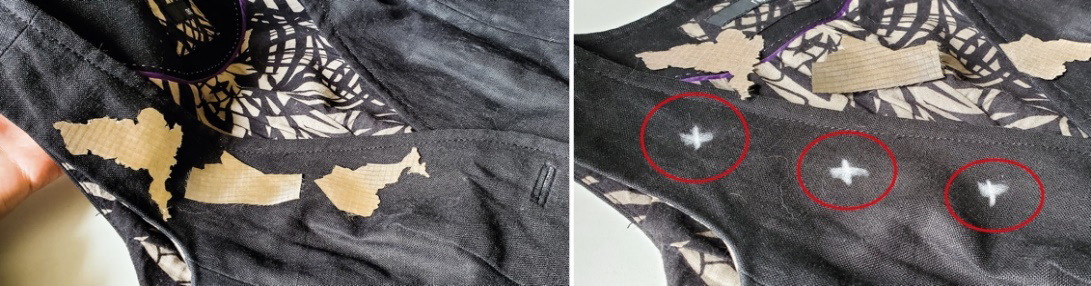
Figure 7.24 – Chalk marks for where the wires will push through
- The underside of where the conductive fabric will be placed is where you will start. This is where I put my wires, which I push through the back of the fabric. You can carefully cut open a small part of the fabric inside and slide the wire into it for a neater finish.
- The wires need to be poked through the fabric from behind so that they will touch the conductive fabric on the front. Figure 7.25 shows the wires that I have run along the inside of the vest and then poked through where I left the chalk marks.
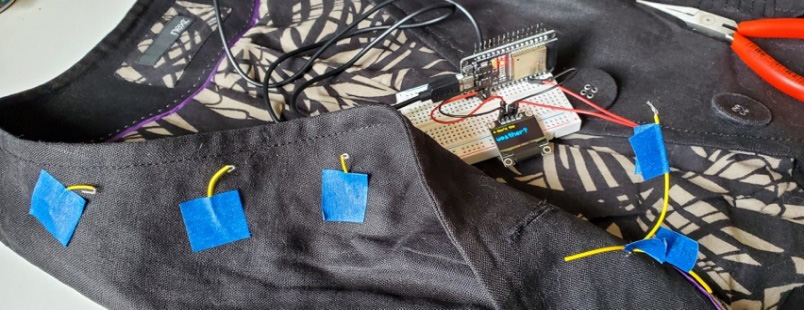
Figure 7.25 – Wires through the vest
- In my wearable, I taped down the wire until I was ready to sew. The tape stops the wires from slipping back into the garment. I also mapped the ends of the wires to which pins on the ESP32 board they would connect. I wrap masking tape around the wire and write the pin number on it. Always test and check the connections before sewing them in place.
- When you have your wires in place, sew them with conductive thread to the fabric. When the wire is sewn, the conductive fabric will register our touch.
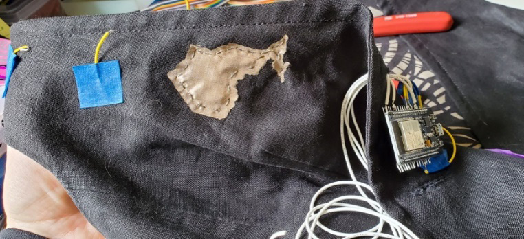
Figure 7.26 – One of the map pieces sewn into place
- After sewing the wires with conductive thread, place your conductive material shape over the top of these sewn wires.
Stitch the conductive fabric in place with conductive thread. You can use quite large stitches for this. You also don’t have to use conductive thread for it necessarily. I used conductive thread mostly for the aesthetic. Then, knot it to the sewn wire piece on the underside.
- Test the connection again once it is sewn into place (Figure 7.27). Your screen should light up with the location’s current weather data.
- Follow this method for all the other shapes in your wearable:
- Sew the wire underneath with conductive thread
- Place your conductive material shape on top of that sewn piece of wire
- Sew the shape into place
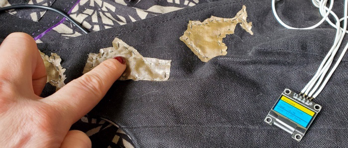
Figure 7.27 – Testing the touch connection
- Once you are happy with your circuit and how you’ve mapped and planned it out, decide whether you want to include a vibration motor. A vibration motor can be a great way to send immediate feedback to the wearer that they have successfully touched the map piece.
An additional design consideration for the wearable is that I’ve decided to mimic a pocket watch style design for this vest/waistcoat. With a 3D printer, you can make shaped casing that will hold your components. Figure 7.28 shows a 3D printed pocket watch casing for the OLED, with a front and back piece:
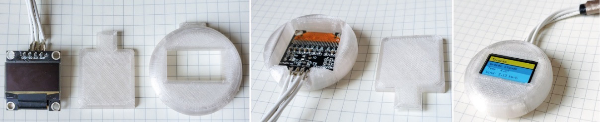
Figure 7.28 – 3D printed casing for an OLED
This was designed and made for me by Fergus Fullarton Pegg, and he’s made it available on Thingiverse if you’d like to print your own in a color of your choice: https://www.thingiverse.com/thing:5469722. As part of the overall piece, it completed this wearable nicely!
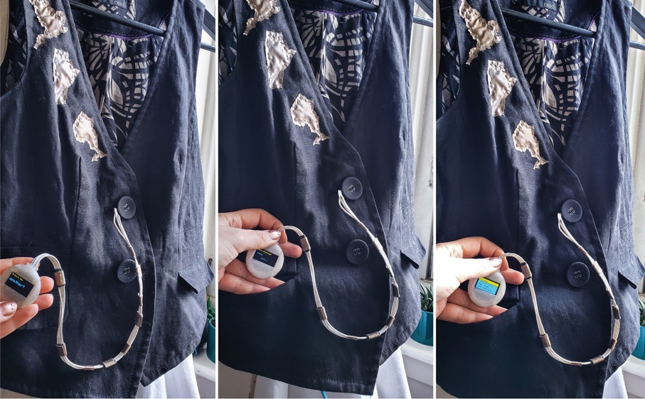
Figure 7.29 – The finished piece
The photos in Figure 7.29 show the final piece with the touch maps made from conductive fabric, the OLED screen as a pocket watch, and the ESP32 board hidden behind the button area.
One thing to note is that if you want to use the circuit wherever you are, I often set the Wi-Fi network to one shared from my mobile phone. I create a mobile hotspot and connect to the hotspot in the code, adding my SSID and password.
When you have finished assembling your circuit and double-checking that your connections are secure, we can begin the process of coding the circuit.
Installing the library and uploading the software
Open the code (https://github.com/cmoz/Ultimate/tree/main/C7/C7_WeatherAPI) and copy it. Create a new sketch and paste the code into it. Then, plug the Feather board into the computer.
We need to install a library to get this code working. Open Library Manager and search for the ArduinoJson library. We need this library in order to parse JSON files. Parsing JSON files means extracting the information that we are getting back from the API request and being able to display it in a useful, readable way. When we tested our API connection earlier, we were presented with all the information returned from the weather website on the web page. This wasn’t very easy to read, as shown in Figure 7.21.
This library will help us to display the exact information we want on the OLED. Using the library means we only need to add a few lines of code to our Arduino sketch and it will do all the hard work. There is a lot more information online at https://arduinojson.org/ about this library.
Once we have the library installed, let’s look at the code.
What’s the code doing?
This is undoubtedly the most substantial code we’ve worked with so far. There’s a lot in it, but if we look through it, you can start to read through and understand what each part is doing. Let’s look through some parts of the code so we can understand it better.
Let’s start here:
- The long getRate = 15000 line declares that our variable called getRate will run for 15 seconds. This is our way of capping how often the calls to the API will happen. On our free account, we can make 60 calls a minute, but we want time to read the output and we don’t want to max out the account.
- The next part of the code is about defining a string variable for each location. This is the information we are requesting through the API. You’ll have different information here depending on the locations relevant to your own project.
- I’ve called these variables base_t for Toronto, base_w for Winnipeg, and so on, so that I don’t forget which variable refers to what place.
You might want to rename your variables to match your project better. Here is the code:
String base_t = "http://api.openweathermap.org/data/2.5/weather?q=Toronto,ca&units=metric&appid=yourAPIkey";
String base_w = "http://api.openweathermap.org/data/2.5/weather?q=Winnipeg,ca&units=metric&appid=f yourAPIkey";
String base_y = "http://api.openweathermap.org/data/2.5/weather?q=York,uk&units=metric&appid= yourAPIkey";
String units = "metric";
String weatherUrlT = base_t;
String weatherUrlW = base_w;
String weatherUrlY = base_y;
I followed this convention further along in the code, for the weatherUrlT string, for example. Be sure to change all the locations where this variable appears.
One feature of Arduino 2.0 is that we can select the variable name we want to change, right-click to see the sub-menu, select Change All Occurrences from the menu (as in Figure 7.30), and then start typing the new name for your variable. This will update them throughout the code for you.
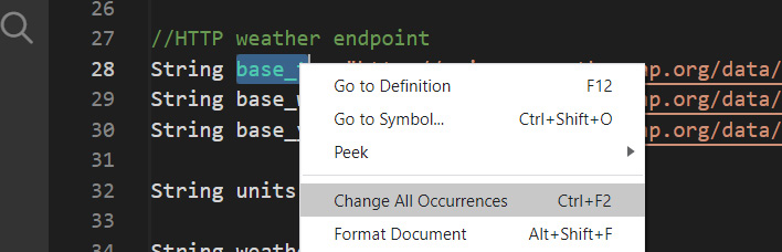
Figure 7.30 – Changing a variable name throughout the entire code
The next part of the code that you may need to adjust is the size of the OLED screen that you are using:
#define SCREEN_WIDTH 128
#define SCREEN_HEIGHT 64
In the setup() function, you’ll notice a function being called, oledStart(). This is a function that we want to run when everything has been loaded in the setup() function. If you scroll down to near the bottom of the code (around line 200 or so) to find this function, you’ll see the following:
void oledStart(){
  oled.invertDisplay(false);
  oled.clearDisplay();
  delay(500);
  oled.setTextSize(1);
  oled.setTextColor(SSD1306_WHITE);
  oled.setCursor(0, 0);
    oled.write(0x03);
  oled.println(" How's the");
  oled.setTextSize(2);
  oled.setCursor(0, 20);
  oled.println("weather?");
  oled.display();
  delay(2000);
}
This code will display a message that reads, How’s the weather?, with a heart character too, as defined in oled.write(0x03). The oled.setCursor() code comprises the.setCursor() function, which is the prewritten code that will set the cursor location, and oled is the object that we want the .setCursor() function to affect. The function defines where we want the text to start: the first number corresponds to the horizontal placement and the second to the vertical placement. Play around with these values and the text to display the message that you want.
Our loop() function has one main part of code, an if statement that will react when the touch has been determined. The if(touch1detected) statement is repeated three times, once for each possible touch.
This code clears the display, sets the touch1detected bool to false, and calls the displayMessage(String) function; this has a String parameter. The function takes the String sent to it – in this example, the displayMessage() function, passes a String value containing "How's Toronto" – and uses it in the code.
We could write all the OLED instruction code directly into this block and not put it in its own function. However, we would end up writing a lot of repeated code. Putting code in its own function is a good idea to save repetition:
if(touch1detected){
    oled.clearDisplay();
    touch1detected = false;
    Serial.println("Touch 1 detected: GPIO 12 TO");
    displayMessage("How's Toronto?");
       if((millis() - prevWeatherCall) > getRate){
                updateWeather(weatherUrlT);
                prevWeatherCall = millis();
                delay(100);
                oledDisplay(parsedWeather);
                delay(getRate);
                oledStart();
           }
 }
The code will check the rate of our call to the API, and if it is bigger than the getRate variable we set earlier in the code, we can make another call.
If this if statement is true, it will do the following:
- Get the updated weather.
- Set the new timer.
- Display the parsed weather information on the OLED screen.
- Then, it will wait to give the wearer a chance to read the weather information.
We end this if statement by launching the oledStart() function again to reset what’s visible on the OLED screen. This lets the wearer know that they can press a different conduct map shape for another location.
Let’s have a look at the updateWeather() function that is called. This first allocates the payload String, with the function httpGet(location). The value of the location String is the URL to the API service. This was provided by calling the updateWeather(weatherUrlT) function in the code. This has our location information and API key, in this example, it’s appended with T so we know it’s for Toronto. When we called this function, we called it with the String location argument, which was this line of code, with the weatherUrlT String sent to the updateWeather(weatherUrlT) function:
void updateWeather(String location){
 payload = httpGet(location);
 if(payload != "HTTP Error"){
 DeserializationError error = deserializeJson(jsonWeather, payload);
    if(error) {
      Serial.print(F("deserializeJson() failed: "));
      Serial.println(error.c_str());
      return;
    }
    parsedWeather[0] = jsonWeather["name"].as<String>();
    parsedWeather[1] = jsonWeather["weather"][0]["description"].as
<String>();
    parsedWeather[2] = "Temp: " + jsonWeather["main"]["temp"].as
<String>() + " " + tempUnit;
    parsedWeather[3] = "Wind: " + jsonWeather["wind"]["speed"].as
<String>() + " " + windUnit;
  }
  else parsedWeather[0] = payload;
  oledDisplay(parsedWeather);
}
The parsedWeather[x] String array contains the information about the four fields that we want to display. Then, we call oledDisplay() to display that information as processed by the JSON library we are using.
If you look through the code, you’ll see many functions that we have written and that we are using. If you look through them line by line, you will see code that you can edit to alter the way information is presented, for example.
Extra challenge
That is a lot of information, making, and coding. One of the best ways to consolidate your learning is to challenge yourself and play around with the code.
Look through the following functions:
- void oledDisplay(String parsedJson[4])
- void oledStart()
- void displayMessage(String message)
Edit some of the OLED code for the visual representation of the information. Try to look through some of the other code snippets to see where the information is passed through to a function and how altering some code can change the way that things function.
You can also add code to include vibration. When should this happen? This is great feedback for the wearer, so look at your code, revisit how to add the vibration motor, and what code to add.
When you’re done, run a check through your code first to be sure it compiles. When it has compiled, upload it to your board. Be sure to check that the board and port are correctly selected after you’ve plugged your board into your computer. If there are errors, check it against the original code that was in the link provided.
Now that we’ve built a project with a focus on wellbeing, let’s look at some of the real-world examples of projects to connect people.
Examples of design and innovation for wellness purposes
Sensory tools, wearables, and fabrics are used in various ways with the goal and effect of improving wellbeing. Research by Tan, J., Chen, A., Shao, L., Kim, H., & Ge, L. (2022) details an e-textile sensory tool for people with dementia. Touch triggers different effects, from flashing illumination to sounds, such as bird calls and the sea. They have used embedded conductive cushions, knitted conductive tassels, and hand-stitched conductive feathers. This is a co-design process and they are hoping to encourage the use of e-textiles in dementia care.
Another example of keeping close and connected in this way is within the work of Warraich, M U; Rauf, I; and Sell, A., (2018). This research also uses a co-design process to design wearables with the purpose of monitoring and improving the emotional wellness of the elderly. They highlight the importance of including the elderly in the design process. They point out that wearables that track the state of the wearers exist but only with a “one-size-fits-all” approach. Designing and making a more personal item with the involvement of future wearers themselves could produce a more suitable item for them to wear.
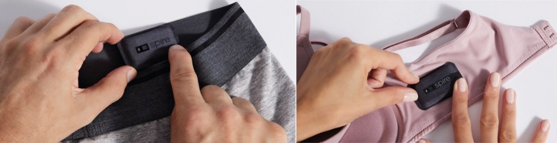
Figure 7.31 – A Spire health tag
Another designed product used for emotional sensing includes the Spire health tag (2018), as seen in Figure 7.31, a discrete clothing-adhered health monitor that is attached to a waistband or bra. It tracks breathing patterns to determine the level of stress a wearer might be feeling. It is marketed for health and wellness. This started as a Spire Stone but that was discontinued in 2019. The tag stays on the clothing you choose to attach it to and its battery lasts 1.5 to 2 years. The tags are washable, so it’s anticipated that you leave them where you stick them, and they continue to track you consistently throughout the year.
This is an interesting wearable because it’s one that the wearer doesn’t have to think about using. It stays charged and is washable, so the idea is that you have several, all placed on items such as underwear, and then you leave them in place.
Another wellness wearable that I’ve come across is Cove (shown in Figure 7.32). This is a headset to be worn twice a day for 20 minutes and vibrations activate areas to keep you calm and emotionally balanced. The potential benefits are better sleep, less stress, and improved mental performance.
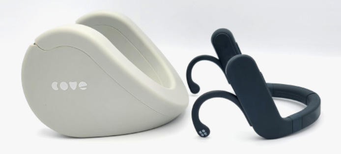
Figure 7.32 – A Cove headset
There is also a tested prototype, Dormio, which is a hand-worn sleep tracker (Figure 7.33, credit: Oscar Rosello https://creativecommons.org/licenses/by/4.0/) and an associated app. This records dream reports (using Bluetooth to a mobile or computer). Interaction with Dormio happens through different stages of consciousness. This includes waking, during the onset of sleep, during sleep, and so on. You can find out more about the project at https://www.media.mit.edu/projects/sleep-creativity/publications/ and http://www.adamjhh.com/dormio.
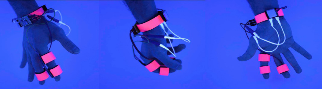
Figure 7.33 – Dormio (credit: Oscar Rosello)
The wearer decides what they want to dream about, whether solving creative problems, reflecting on an emotional issue, or finding a new perspective on something specific. It’s explained that the potential utility for a device like Dormio is to specifically enhance performance on a task pre-determined by the user, with the researchers citing that correlations between dream content and sleep-dependent memory processing have been reported in several studies. This paper, Dormio: A targeted Dream Incubation Device, is cited at the end of the chapter.
One last tip – a dynamic SSID and password
From our examples, we’ve been coding in our SSID and password information. This is okay, but if we do want our device to change locations or to use another network, what do we do? We must reprogram our ESP32. There is another solution. We can create a Wi-Fi manager.
This is beyond the scope of the book, as our focus is on the wearables themselves. However, a Wi-Fi manager will help you move forward with making your own wearables. You can come back to this little section later when you have completed more ESP32 projects and you want to implement one; it’s an advanced skill.
The ESP32 has two main modes for Wi-Fi. They are Station Mode, where the device connects to another Wi-Fi router, and Access Point Mode, where the device acts as the Wi-Fi router. We want the Wi-Fi credentials to come from us or a user. This means that the ESP32 will need to be in Access Point Mode first, then it waits for credentials, then it shifts to Station Mode.
The library (https://github.com/kurimawxx00/wifi-manager) consists of three main files. There is an HTML file loaded (Figure 7.34), which presents the form for users to enter their credentials. There is the .ino sketch, which checks for saved connection information. If none is found, it will load the credentials form. It saves the information in memory called EEPROM. We will use EEPROM in Chapter 13, Implementing the Best Solutions for Creating Your Own Wearable.
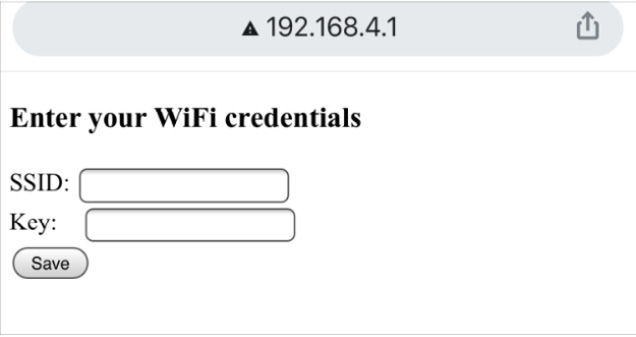
Figure 7.34 – Wi-Fi credentials
Lastly, there is also the WiFiManager.h file, which does the communication. Rather than me explaining more in detail, if you want to implement this, then you should visit GitHub, where there is a tutorial link for how to implement the code. You’ll need to add a button on pin 13, to trigger it to search for the Wi-Fi credentials, see whether there are any, and launch the HTML page.
Another tip to make sure the files work is to put them in the same folder together. Then, they will open in tabs (Figure 7.35). You will get an error message if the HTML.h file doesn’t load with the WiFiManager-example.ino file.
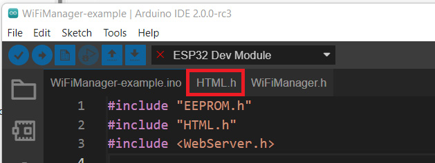
Figure 7.35 – The files opened in tabs in the Arduino IDE
Once you have advanced your skills with the ESP32, you might want to try this out. You should edit the HTML page so that it suits your wearable.
This brings us to the end of the chapter, and it’s been a full one!
Summary
This chapter has explored the world of microcontrollers and how we can use them to bring more life to our wearables. We looked at what a microcontroller is and what its main features are. We then focused on the powerful ESP32 after learning about its predecessor, the 8266, which started a huge shift in wearables because of its inclusion of Wi-Fi capabilities at a much lower cost. Our board of choice was the Adafruit Feather HUZZAH ESP32 for several reasons, and it fit our project well. We looked at creating a wearable that would allow us to keep family and friends in our thoughts. This was a positive mental health and wellbeing project so we felt connected to loved ones who were at a distance.
To enable this technology and interaction, we looked at creating symbols that represented them and then accessing live data online. This was achieved through accessing an API service: in this example, it related to weather data. We then looked at making a non-traditional e-textile board usable in our wearable projects. We then put it all together, which included displaying data on an OLED screen when the conductive map symbols were touched.
Overall, this was a very involved chapter with a lot of new concepts introduced. I hope you have realized how much progress we are making. Now, we are ready to learn about prototyping. This will contain a mix of theory and practical activities. So, let’s get our thinking caps on and jump straight into the next chapter!
References and further reading
Tan, J., Chen, A., Shao, L., Kim, H., & Ge, L. (2022). Customization of e-textile sensory tools for people with dementia. The Design Journal, 25(1), 104-125. https://www.mendeley.com/catalogue/8a2d539d-9f27-31fa-8d1b-58357ad3232a/.
Hua, D., Wei, H., & Blevis, E. (2018). MemoryPin: Turning digitally co-present moments into tangible memory keepsakes. In DIS 2018 - Companion Publication of the 2018 Designing Interactive Systems Conference (pp. 253–258). Association for Computing Machinery, Inc. https://doi.org/10.1145/3197391.3205445.
Warraich, Muhammad Usman; Rauf, Irum; and Sell, Anna, Co-creation Model to Design Wearables for Emotional Wellness of Elderly (2018). BLED 2018 Proceedings. 6. https://aisel.aisnet.org/bled2018/6.
Haar Horowitz, A., Cunningham, T. J., Maes, P., & Stickgold, R. (2020). Dormio: A targeted dream incubation device. Consciousness and cognition, 83, 102938. https://doi.org/10.1016/j.concog.2020.102938.
Carr, M., Haar, A., Amores, J., Lopes, P., Bernal, G., Vega, T., ... & Maes, P. (2020). Dream engineering: Simulating worlds through sensory stimulation. Consciousness and cognition, 83, 102955. https://www.sciencedirect.com/science/article/pii/S1053810020300325?via%3Dihub.
Heshmat, Y., & Neustaedter, C. (2021). Family and Friend Communication over Distance in Canada during the COVID-19 Pandemic. In DIS 2021 - Proceedings of the 2021 ACM Designing Interactive Systems Conference: Nowhere and Everywhere (pp. 1–14). Association for Computing Machinery, Inc. https://doi.org/10.1145/3461778.3462022.
Singhal, S., Neustaedter, C., Ooi, Y. L., Antle, A. N., & Matkin, B. (2017). Flex-N-Feel: The design and evaluation of emotive gloves for couples to support touch over distance. In the proceedings of the ACM Conference on Computer Supported Cooperative Work, CSCW (pp. 98–110). Association for Computing Machinery. https://doi.org/10.1145/2998181.2998247.
A selection of online shops for Arduino-compatible boards:
- https://www.tinkertailor.tech/
- https://proto-pic.co.uk/
- https://www.adafruit.com/
- https://uk.rs-online.com/web/c/raspberry-pi-arduino-development-tools/arduino-shop/
- https://www.arduino.cc/en/hardware
- https://www.sparkfun.com/categories/300
Review questions
- Can we only use e-textile boards for our wearables? Explain why or why not.
- What are the three main parts of the microcontroller?
- What are the two main advantages or extra features that an ESP32 board offers us?
- Describe the process for developing a wearable in stages and why it is a good idea to carry it out this way.
- What is an API used for?
- Why did we need an API key?
- Can we edit all occurrences of a variable or other element in our code at once, or do we need to do this one by one throughout the code?