
14
Delving into Best Practices and the Future of Wearable Technology
This chapter will provide information on the steps to take to help find solutions for common errors or issues that can happen when we prototype. We will look at a few handy tips to help us with our wearable journey, as well as understand how to set up our circuits so that they last. We will also have a look at batteries and power solutions.
We will look at troubleshooting and some of the common ways you can take a step-by-step approach to finding the problem. We will finish up with a look at the future and what the world of wearables may hold! What are scientists, technologists, engineers, and designers exploring in these intersections? For example, designers and engineers are creating medical devices worn on the body and collecting essential information for healthcare. We look toward the possible future directions for wearables, on-body systems, and creative circuits. We discuss “What does the future hold?” through learning about where this exciting research is taking us.
In this chapter, you will consolidate your learning using my tips and tricks to help you continue with your wearable practice.
By the end of this chapter, you will have additional resources to continue with your own learning journey. You will understand the essential information about providing power to your circuits and ways to find the errors that are preventing your wearables from working. You will have thoughts about where the future of wearables may be heading, and hopefully, you’ll be planning your own first project!
In this chapter, we’re going to cover the following topics:
- Best practices
- Additional techniques
- Taking your prototypes further
- Power considerations
- How to troubleshoot
- What’s in the future?
Technical requirements
This chapter includes new techniques and explores ways to move your circuits from prototypes to even more ambitious projects, so we don’t have a specific requirement list.
Best practices
I hope you’ve had an exciting journey with me from our first steps in learning about electronic circuits to using conductive threads and fabrics and exploring e-textile toolkits. We’ve whizzed by several Arduino systems and explored some of the functions of ESP32-based boards. Throughout all the learning, we also had time for theory, the important consideration of why we want to make wearables, and what was made before us. We looked to a Design Innovation method to help create wearables with purpose. Hopefully, you’re now equipped to bring your wearables to life through recreating that process, from early concept prototyping to making and using your wearable.
This chapter is a place for some of the extras that can help to improve or bring your wearables to the next level or just simplify the process for you – some of which I’ve learned over the years of making and teaching, and all of which I’ve found useful.
Let’s start with a few pointers that can help make a project all the more successful!
A few handy tips
There are many things you can do to make your wearable journey a more enjoyable and active experience – let’s start with storage.
Storage
It’s all about small parts! Creating wearable systems means there’s a world of small parts. You’ll probably find as you progress that you start collecting many different resistor values, fabric samples, and wire thicknesses. Sometimes, getting a delivery of new items feels so exciting that it’s easy to lose or misplace some of these small items. The best idea is to invest in some good storage containers of various sizes. Separate your items by type or categories – for example, I group the sewable items. Figure 14.1 shows one example of storage I found at Christmas time and used to store baubles (on the left), or these Muji (https://www.muji.eu/) drawers (on the right), the perfect size for components:
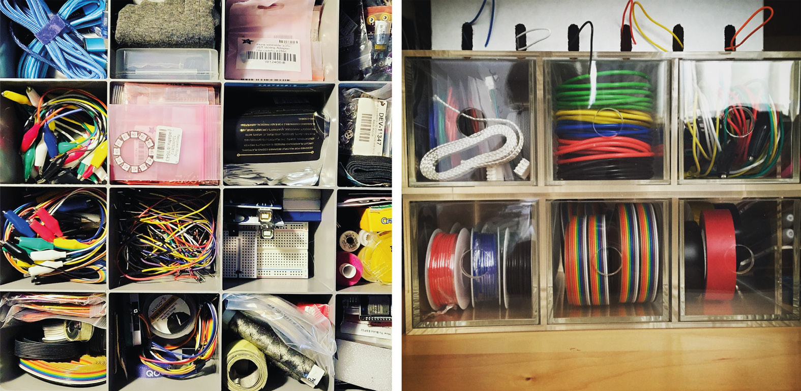
Figure 14.1 – Storage options for components
The best thing to do when unboxing all your parts is to separate them by type. It’s nice to have all your resistors in a separate place from your LEDs, or even to have separate places for different LED colors and resistors of different values. Most hardware or craft supply stores sell plastic boxes that will make this easy and fun to sort out.
I also have a toolbox that I use if I want to bring my tools with me to work on projects. As shown in Figure 14.2, there are many options for toolboxes that suit your size requirements. I love Trusco toolboxes because they have a great range to choose from and they are well made. Suppliers for Trusco that I’ve found include https://www.labourandwait.co.uk/collections/trusco and https://tinkerandfix.co.uk/collections/trusco. They may seem expensive, but I’ve had mine for well over a decade and there’s no sign of even a dent in it. They are great quality and will last a lifetime:
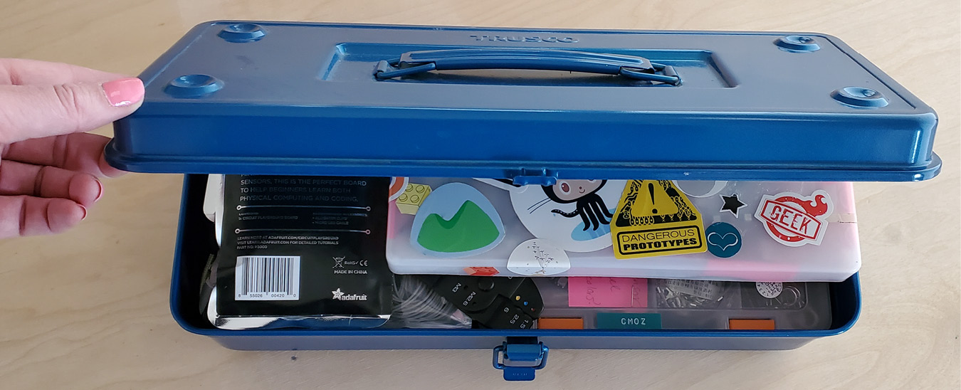
Figure 14.2 – My Trusco toolbox and the tools I store in it
I also have a little yellow plastic toolbox that I carry around too depending on where I’m going and what components or tools I need. These can be very handy and a good low-cost solution. This one (see Figure 14.3) has a lot of storage areas with a pull-out tray:

Figure 14.3 – A small plastic toolbox solution
Also, when ordering components or kits, they sometimes come in a plastic box. Here are some examples (see Figure 14.4) of boxes I got from Proto-Pic (https://proto-pic.co.uk/), which I turned into storage for projects I’m working on, and a container that a kit once came in, which is a great size for storing loose components or active projects that I’m moving or carrying around:
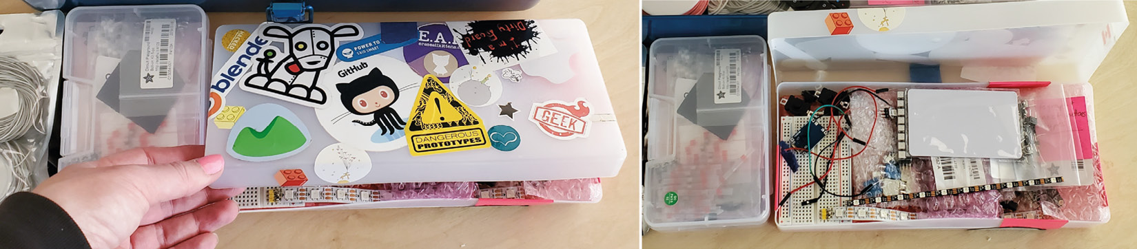
Figure 14.4 – Using storage solutions from Proto-Pic packaging (right) and another component box (left)
I also usually separate my soldering items for taking them with me. These items all fit nicely in a component box and the boxes make great solutions for carrying all you need. Shown in Figure 14.5 is one that I’ve been carrying with me for a very long time:
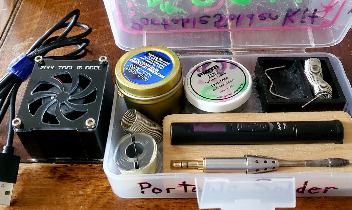
Figure 14.5 – My portable solder iron box made from a reused plastic box I had
You can find small portable-sized solder, tinning flux, and solder irons so that you can bring your practice with you!
Lastly, it’s a good idea to get storage boxes for fabrics, conductive materials, and threads, so that you don’t lose small sewing parts. I have sealed storage, so everything is kept organized and tidy, as well as sewing boxed so I know where to find what I need when I’m sewing.
Storage of Conductive Materials
A little tip to remember is that many conductive materials and threads can oxidize over time. They often need to be stored in sealed bags to prevent discoloration. Also, try not to handle these materials unnecessarily. Sometimes, the oils from our fingertips can leave marks on these materials.
Having quick access to the materials and tools you need makes a big difference when you’re working on a project. If things are handy, you’ll be much more likely to get on with it when the inspiration strikes!
Documentation
Document your project, then share it! One way to encourage you to make and build projects is to share what you’re doing. When you share on a site (see Figure 14.6) such as Instructables (https://www.instructables.com/member/CMoz/), you also can see what other people have been making. Hackaday (https://hackaday.com/) has fresh hacks that are interesting for the engineering community every day. I also document a lot of projects on my personal website, https://christinefarion.com/, so it doesn’t matter what projects you document or where you do it – just do it! Here are some examples of documenting your work:

Figure 14.6 – Sharing your wearable projects, either on a personal site (left) or Instructables (right)
Seeing what others make can be very motivating and inspirational. Also, documenting your projects is a great way to remember what you did and how you did it. Forgetting how to connect components or code elements of your wearables is easily done, so having a record of it with good photos and diagrams is helpful for you to also remember how you did it or what aspects you want to fix or improve. When taking photos, try to be sure your wires are clearly visible, color-coded, and there’s not too much of a spaghetti junction happening.
Sites to help your prototyping
There are many sites that can help support your project planning. One of these sites is Circuito, available at https://www.circuito.io/, where you can make schematic diagrams of the components (see Figure 14.7). You can drag components into the main work area and it has sample code you can use to test your components too:
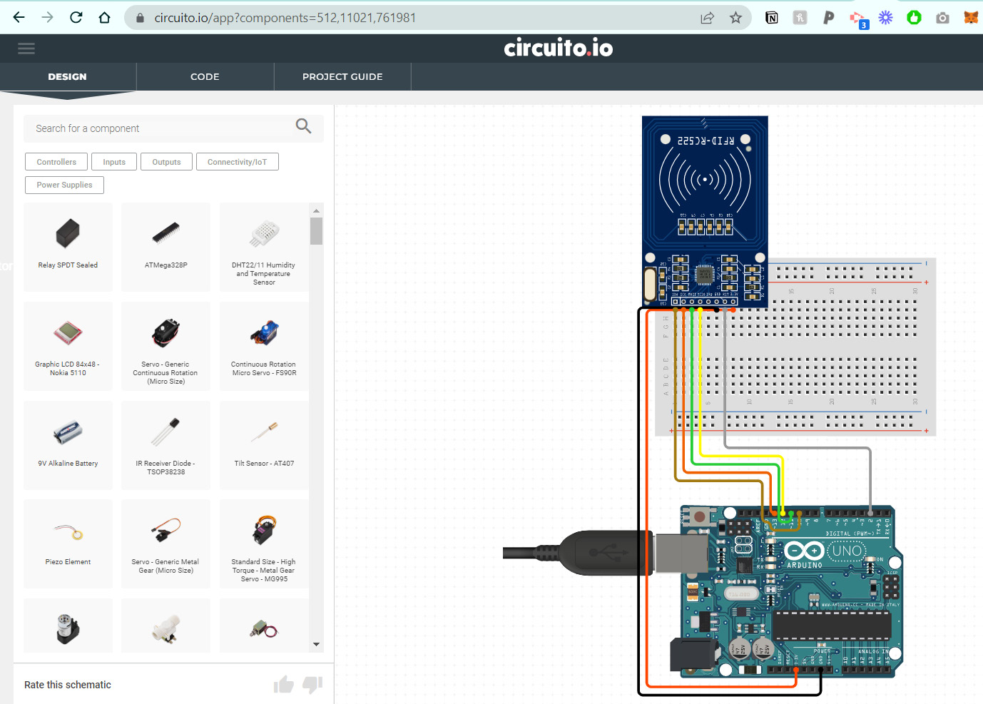
Figure 14.7 – Circuito for mapping out a schematic diagram
It can be a good way to try an idea without buying the boards and components. Similar to Circuito is a service on DigiKey (https://www.digikey.co.uk/schemeit/project/) for mapping out your projects. There are components for you to drag into the project area (see Figure 14.8). They have a huge range of components in their catalog, so it’s worth a try:

Figure 14.8 – Using the resource at Digikey
Another popular site is TinkerCad (https://www.tinkercad.com/), which you can use for circuits and designs. These sites can be useful to try out your ideas before you’ve bought the components. I use Fritzing for creating schematics (www.fritzing.org), which I’ve used in this book, as well as for tutorials I make online (see Figure 14.9):

Figure 14.9 – Fritzing for schematics
Fritzing now has a donation fee of €8 to download and keep the software. If you are going to make many diagrams, then I find it is worth the small fee.
Identifying opportunities
When making wearables, it is important to find what interests you for your inspiration. Sometimes I look to sites such as the UN’s Sustainable Development Goals (https://sdgs.un.org/goals), of which there are seventeen. This could be a great starting point for an informed wearable. Similarly, think of cross-fertilization, meaning looking to other fields. These are fields that are different from ones you might be directly involved in. This could be architecture, science, arts, industry, fashion, or nature.
The following are suggested possibilities for creating new and exciting wearables:
- You might look at increasing your wearable’s complexity – adding more outputs and inputs just to test your coding skills and circuit design.
- This might develop into designing with a theme, so maybe one that is all sound-based, or only light-based.
- You could base a project around one microcontroller so that you try it and use the features – for example, trying an ESP32 circuit or Flora-based wearable if you haven’t before.
- Challenging yourself to a £20 or $20 build, or a build with some cost limit, can also be a fun challenging way to build up a project. This could inspire you to use as many recycled or reused parts as possible – a challenge for building with only a fiver!
- Maybe you want to limit yourself in terms of the amount of time. Could you make three projects in three days? Or follow a seven-day build? How much could you accomplish with a finite amount of time – say, 30 minutes? Go!
- Expand a current project you’ve made. Could you take a project you’ve made, perhaps from following along in this book, and expand it or add to its capabilities?
- Choose a different body part to create a wearable. This one I love. You might take an existing project and make it for a different body part. How would you need to adapt it? Or you can simply try making a wearable design for a part of the body you haven’t yet designed for. Designing for the neck or ankle requires different challenges and skills and can help advance your skill set in a fun way.
- Make things wrong or opposite. Use a unique or different component – meaning use a sound output where you might typically have a screen or use a button in place of a typical slider component – or the opposite body part or function. Shaking things up can spark new ideas for your creations or ways to solve a problem. It’s important to find the fun when hacking your own design.
Through identifying new opportunities, you will have an endless stock of wearable ideas. Don’t forget to record ideas in your notebook as you go.
Additional techniques
The techniques in this section are ways you can make your wearables more durable or construct them in different ways. If a circuit I’m working on is particularly fragile or has very thin wires that could break off from where they are soldered, I like to make it more durable. I use a more permanent solution than what covering ends with fray check or clear nail varnish can accommodate.
Using resin will give a very sturdy bond and covering for your wires. You can buy epoxy resin, which comes in two bottles typically – one is a hardener and when you mix it with the other, they will cure (harden or set) over a specific period of time. This can often be 24 hours. However, many gel nail polish systems are made from a resin, which cures with UV lights in a minute or so. You can be very specific about where you want the resin to go and you don’t need to mix large quantities – you don’t need to mix anything! This can be a great way to add the amount you want to the specific part of the system that needs it. One of the gels I have used in the past is the NYK1 brand, which has resin in a pot (see Figure 14.10) as shown:
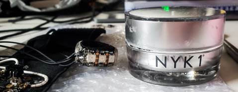
Figure 14.10 – Resin nail gel in a pot
The pot of resin allows you to use a small brush to apply it to where it is needed. You will need to keep your resin out of sunlight or it will start to cure! I made the mistake once of leaving the lid half off while I accessed the resin and one side of it is now hard and unusable.
I made a ring with NeoPixels and it had a join that was very fragile where the wires met the solder pads. I applied the UV nail resin to this seam and then put it under a UV LED light. In Figure 14.11, we can see the ring under a UV LED lamp:

Figure 14.11 – Curing gel polish under a UV lamp
It cures in the UV lamp for around 60 seconds. The lamp is made for curing nail polish and can be purchased from online retailers for around £20 or $20 at the time of writing. I have seen tutorials for making your own UV lamp Arduino system using UV LEDs with a timer, so you could make one.
Look out for UV-activated gel nail polish – you can get colors such as black for a particular project, though I usually go with clear.
Similar to that system is a product called Bondic®. This is a liquid plastic system that comes with the resin in refillable tubes, as well as a UV LED that you press against the battery and aim at the resin. It only takes a few seconds for it to harden. You can use it to create a durable connection, as shown in Figure 14.12. I used it on wires on a NeoPixel ring because they kept pulling off. I added the Bondic, cured it, did one more layer to build it up, and cured it again:

Figure 14.12 – Using Bondic® to make wire connections more durable
Use a layer-by-layer approach, use a thin amount then cure it, then apply again and cure it. In the final image (on the bottom right), you can see I’m now pulling at the wires, and they do not move away from the NeoPixel ring solder pads at all. It’s very durable. More information about Bondic is available on their site: https://bondicuk.co.uk/.
It is worth mentioning 3D printing as a technique that can be used to add to your wearables. We saw the beautiful wearables created by Anouk Wipprecht in Chapter 1, Introduction to the World of Wearables, and there is an interesting article online that features some of her 3D-printed creations: https://parametric-architecture.com/3d-printed-interactive-wearable-designs-by-anouk-wipprecht/. Another mesmerizing work using a variety of tools and skill sets is the work created by Behnaz Farahi, Returning the Gaze, 2022, shown in Figure 14.13:

Figure 14.13 – Returning the Gaze by Behnaz Farahi, 2022 (photographer: Nick Soland)
Returning the Gaze is a cyber-physical robotic installation by Behnaz Farahi supported by Universal Robots for ANNAKIKI’s Milan Fashion Week. More information can be read at: https://behnazfarahi.com/. The project is described as a wearable that “… brings together robotics, fashion, design, feminism and critical thinking in order to critique the asymmetry of social and political power relations between men and women.” What is important to note as well is that this is a wearable that also uses the space and place around the wearable itself. It bridges the environment through the monitors that are projecting the wearer’s eyes to the audience.
Using 3D printing can be elaborate, as we’ve read in the previous examples, but it can also be a way to test out a prototype idea. This 3D-printed part (see Figure 14.14) allows me to incorporate an 8 LED NeoPixel stick and two buttons:
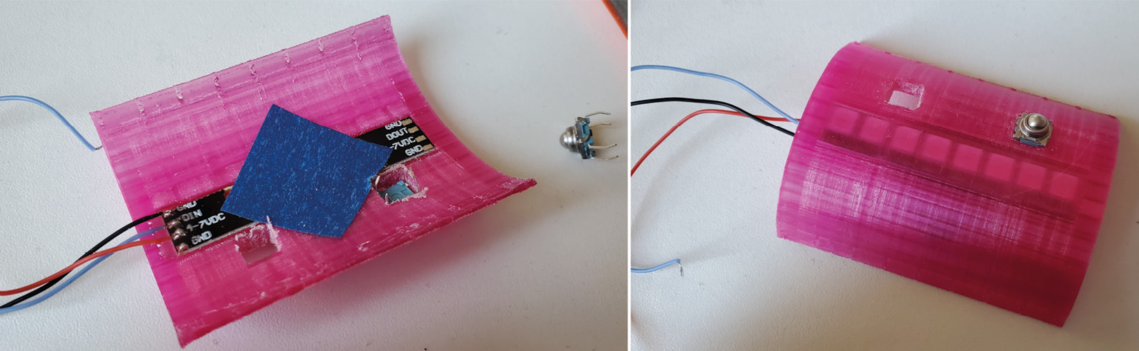
Figure 14.14 – 3D printing for prototyping
This piece will give rigidity to a circuit that is then added to a soft cloth wristband. It allows me to test it with a quick structure. To 3D print, you may be able to go to a local hackspace, maker space, or library to borrow their equipment. They would usually also help someone to learn how to use the tools. There is free software such as Cura (https://ultimaker.com/software/ultimaker-cura) and Prusa 3D (https://www.prusa3d.com/) to help you make and send files to a 3D printer.
3D print technology has been around since around 1981 with documents supporting research in Japan. Hideo Kodama was looking for prototyping solutions. Around the 1990s, startups began to experiment with 3D printing technologies for prototyping and machines were expensive and not user-friendly. Around 2005, Open Source allowed a more rapid spread of innovation and interest by launching an initiative to create a 3D printer – that could build a 3D printer! In 2008, we saw the first prosthetic leg printed, which helped to bring attention to this technology to the public. Also, in 2015, cat owner Fergus Fullarton Pegg created an orthosis, which is a temporary support brace, for his cat. Working with a vet after his cat was badly injured, Fergus decided to design a leg support with a Form 1+ SLA 3D printer (see Figure 14.15). Using a cast from the vet, he designed an orthosis that would allow movement in the joint and release the front paw naturally:
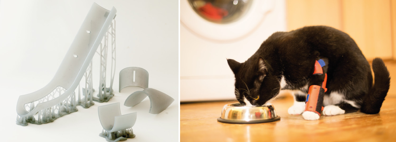
Figure 14.15 – An orthosis for a cat, Sprocket
Prices for 3D printers over time began to decline and the printers got smaller and more portable, which allowed them to be easier to access. 3D printers are now being used in industry to print hearing aids and other medical aids, but also for creating rapid prototypes. New technologies have led to resin printers using UV technology to harden layers, as it prints from liquid, as well as mill style (see Figure 14.16) so that they can continue printing. I’ve seen photos of these hung on walls so that the printing falls into a basket below:

Figure 14.16 – Creality CR-30: The 3DPrintMill, Infinite-Z, Belt 3D Printer
Creality have a range of 3D printers (https://www.crealityofficial.co.uk/), so it’s worth heading to their website to see the different types and possibilities. Lastly, you can experiment with conductive, recycled, medical-grade, and flexible filaments, so there are materials that should be suitable for your needs. If you’re unsure where to start, there is Thingiverse, which has user-submitted printable designs (https://www.thingiverse.com/). You can download the files and print them yourself. There are also 3D printing services, so if you have a design that you need printing, you can usually email a file to a printing company.
Another prototyping material that can be used for creative wearables is a product called Worbla. This is a non-toxic thermoplastic that comes in sheets that can be molded to different shapes using heat. You can get sheets in natural, black, white, red, and clear. When you heat it, it can be manipulated into shapes, but it’s also sticky, so you can build up what you are trying to make to give a prototype depth. Worbla can be heated with a heat gun – the same that we could use for our heat shrink. You may need heat-proof gloves to make this a safe activity, although if you make a mold first and apply the Worbla to the mold, you should be okay. You can find more information about Worbla here: https://www.worbla.com/. They have tutorials and sample uses (see Figure 14.17):
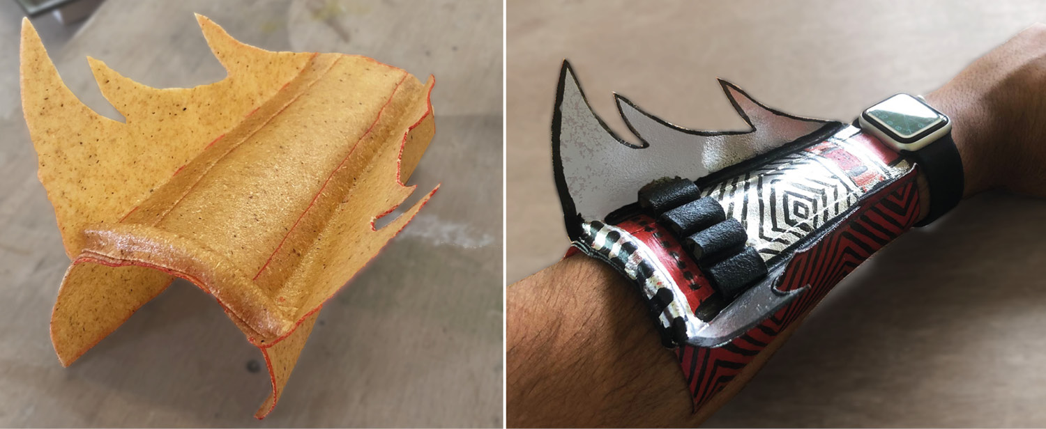
Figure 14.17 – A Worbla project created by Ahmed Zia
The ease of using Worbla allows for rapid prototyping that can help you achieve unusual and durable results. In Figure 14.17, we can see the Worbla in its raw state after being heated up and molded into shape. This is also layered up, as it becomes tacky when heated, so you can glue it to itself. You can build up layers this way and integrate electronics.
Laser cutting is another method that you can use for rapid prototyping. A laser cutting machine can cut a variety of materials, such as thin wood, fabric, leather, and plastics. You will need to check what chemicals are in your materials before you use the laser cutter with them so that they do not release toxic fumes. The laser cutter can cut and etch and is efficient if you need multiple items. Conductive materials can be laser-cut to allow for crisp and precise shapes. You can use the ScanNCut machines too.
There are also programmable embroidery machines that can sew many designs or shapes. Using conductive thread, you can start to build up conductive designs. Alternatively, you could use it to create your patterns and designs, and then sew with conductive thread and fabrics into it for stunning visual effects. Shown in Figure 14.18 is a starting point for a conductive project and the thread is made of steel woven with fibers:

Figure 14.18 – An embroidery machine using conductive thread
One thing to note when using conductive threads is that it often involves some trial and error. Certain threads may be too thick (or thin) for your sewing machine and so may need to be used by hand. You may need to try different thread thicknesses or try conductive thread in the bobbin and not the main thread spool area.
One little trick I will share for anyone who hasn’t enjoyed soldering or finds it too time-consuming – there is another solution when soldering two wires together. You can buy heat shrink sleeves with solder (for example, https://uk.rs-online.com/web/c/cables-wires/cable-joints-cable-sleeving/solder-sleeves). These come in different sizes to suit your wires and they will heat down to fit your wires. I’ve shown the process in Figure 14.19, which uses the shrink sleeves with solder, and then using stripped wires, they go inside the tubes:
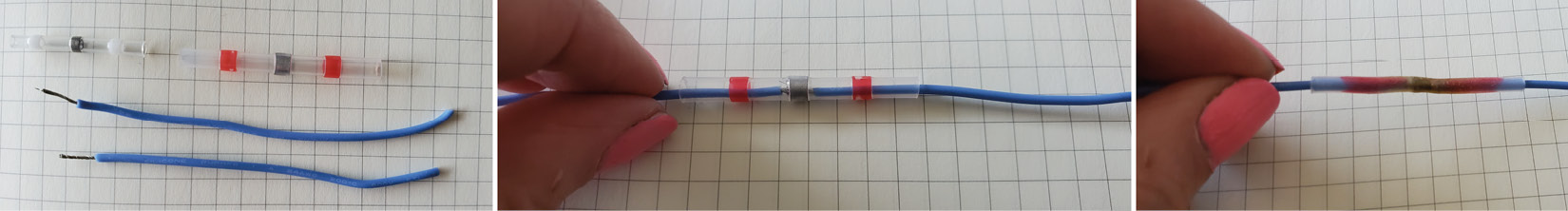
Figure 14.19 – Using heat shrink tubes with solder
Align the tube solder section in the center with the wire ends so that you will melt this center part and the solder will go through the wires and connect them. I would add a little flux on the wire ends to help the conductivity and solder flow. Then, when you heat it with a heat gun, it will melt the solder. Allow it to cool for a moment and then try the pull test. If it comes apart, check that you have applied enough heat and for long enough.
Now that we’ve looked at other techniques we can use for making wearables, let’s explore how you might want to take your wearable designs from an integration prototype to your own circuit board.
Taking your prototypes further
If you’ve made a prototype on a breadboard and then moved it to a garment, it’s likely you’re testing it. This will help you to iterate it and discover improvements. Once these have been worked through, it might be time for you to move it to a circuit board. A printed circuit board (PCB) is the unique design that you’ve taken to a manufacturer to build according to your custom designs and then you can make unlimited copies. One of the boards I’ve made (see Figure 14.20) has slits in the sides so you can attach it to a strap for attaching to clothing or bags:

Figure 14.20 – A PCB manufactured from my design made in Eagle
The circuit board has the traces, the connections between the components, and you would solder on the actual components. You can also get flexible circuits now, but they cost a lot more than traditional circuit boards. I usually go for the thinnest board they offer so that you do get some flex in it. You might want to look at the cost and specifications of what you can buy for low-print runs for your designs at places such as Seeed, (https://www.seeedstudio.com/fusion_pcb.html). They can create small batches of around 10 to 12 circuit boards for you at a very low cost. I’ve also bought PCBs that I’ve designed from Dirty PCB (https://dirtypcbs.com/store/pcbs). Again, these were also low-print run numbers of around ten.
Circuit design software includes Fritzing, as seen earlier in this chapter, and Eagle CAD, which has a limited version for hobbyists (https://www.autodesk.co.uk/products/eagle/free-download), the Easy EDA online PCB design tool (https://easyeda.com/), and KiCAD (https://www.kicad.org/). Using manufacturing services, costs vary, so reducing the risk of errors can be done through several rounds of prototyping and testing. It is very important to make sure all your connections and sensors work.
Typically, some process elements that some wearable designers follow include the following:
- Decide your wearable’s purpose, what question are you trying to answer, and for whom.
- What is your minimum viable product? Understanding what the minimum functionality or features are to satisfy what the wearer wants.
- Work iteratively – make one part of your circuit at a time, get it to work, and then move on to the next part. We’ve been following this process throughout the book too.
- How to make it safe for prototyping? Understanding how to make your wearable safe for the people you want to test it is a priority. This includes power requirements and checking your wiring, as well as how it is used.
- Sourcing parts for your wearable that are cost-effective, available, and standard in case your designs are made by a manufacturer.
- Creating your look-and-feel prototypes – a lookalike prototype so people can see what your idea is going to be like and a role prototype, or a works-like prototype, so people can test the function. Using two prototypes together in this way can help someone understand the overall picture of your wearable. As you make iterations, be sure the changes that you make are a direct result of speaking to people.
- If you are finding it difficult to complete a prototype or work out the code or circuit issues, there is nothing wrong with putting it aside and working on a different project.
- Once prototypes have been tested, build in cost engineering. Don’t do this part too soon because you’ll find you limit yourself. This is about managing the costs involved in making your wearable. You might remove essential features or not make parts of your design. You might want to swap out a circuit board if costs for it have gone up. For example, I was using the ATMEGA48P microchip for a lot of projects, but I soon realized that costs have gone up a lot with chip shortages. An ESP32 chip now is a lot less expensive with a lot more functionality, so I work with that one more. However, it’s important to also realize that you don’t have to stick with a design if it’s just not working. Maybe you need more experience with a component or code, or sometimes, having a rest can refresh you and you may see the problem differently or in a new light. You may want to try different components.
- Don’t forget you can ask for help. There are forums for Arduino-based help – some good forums are on the Arduino website itself (https://forum.arduino.cc/) at Adafruit, where they too have forums (https://forums.adafruit.com/), or you can head to a local hackspace or maker space if there is one near you.
- If you are bringing your design to a circuit board, you don’t have to make one huge feature-packed board – you can make it modular. Make parts of the circuit and check they work. Doing this is a good way to check your designs, part by part. If parts break or need replacing, it is a lot easier to do if it’s only a module or a single part that needs changing and not the entire design.
A Tip for Making: Simplify!
Consider making more designs with fewer features instead of one design with every feature. Sometimes, it’s easy to get distracted by building something that is over-complicated and confusing, instead of creating one thing that works very well.
Creating a PCB is a very exciting process. Using software such as Eagle to create something that doesn’t yet exist is also a very rewarding process. If you are using software such as Eagle, you can download the libraries that companies have created so you can add their components. Two libraries that I add include the Adafruit parts library for Eagle (https://github.com/adafruit/Adafruit-Eagle-Library) and Sparkfun has an extensive parts library that is very useful too (https://github.com/sparkfun/SparkFun-Eagle-Libraries). Using Eagle is beyond the scope of this book, but the libraries should help you on your way. There is also a component search site (https://componentsearchengine.com/part-view/ATMEGA328P-PU/Microchip), so you can search for the parts that you need for your circuits. In Figure 14.21 is a schematic diagram for (left) and the corresponding circuit board (right) of a board I made in Eagle:

Figure 14.21 – Using Eagle to make a circuit board
If you start small with a project that only has a few components, you can work your way up to more complex circuitry. This guide from Autodesk explains how to install libraries: https://www.autodesk.com/products/eagle/blog/library-basics-install-use-sparkfun-adafruit-libraries-autodesk-eagle/. Additionally, I bought the book Make Your Own PCBs with EAGLE: From Schematic Designs to Finished Boards, by Simon Monk, which was great for getting me up and running. There’s no rush or requirement for you to ever move to that stage of prototyping your own circuit boards, but it is important to let you know this is an option. Take your time enjoying making wearables and making a PCB might be something you explore in the future.
Power considerations
Powering the wearables you make is an important part of the overall circuit. Using a Lithium Polymer (LiPo) battery means that it is rechargeable. We need ones rated at 3.7 V for our projects because the circuit boards we are using are 3.3 V-rated, as shown in Figure 14.22:

Figure 14.22 – Varieties of LiPo batteries
The battery’s capacity is measured in amp hours – you’ll see mAh for milliamp hours on the LiPo batteries that we use for wearables. We can use a capacity in the range of 150 to 2000 mAh for our projects. They will be flat and different rectangular shapes. They typically have a foil-type case and don’t weigh a lot, which makes them good for wearable designs. It can be a good idea to provide information for the wearer to know how much charge is left. You can buy a battery capacity indicator (see Figure 14.23) that you can integrate with your circuit:
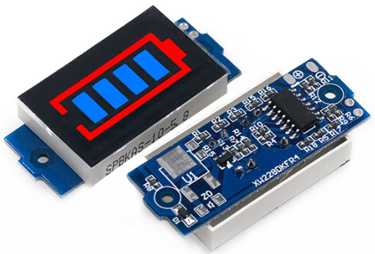
Figure 14.23 – A battery capacity indicator
A battery that is rated at 1 Ah discharges 1 amp for 1 hour, or 0.5 amps for 2 hours, and so on. You might see some batteries with a C rating; this is for describing a maximum discharge rate. If a battery has a 1C rating, it will charge at a maximum of 1 amp over an hour, or a rating of 10C tells us that the battery will charge at a maximum of 10 amps over 0.1 hours, or 6 minutes. Most of the batteries we use will have a 1C charge rate, meaning that the current will charge the whole battery in one hour. Pulling a large current often makes a battery get hot and this can also shorten the life span of a battery.
LiPo Safety
If your battery gets puffy, stop using it immediately. This is from gas escaping and building up inside the battery. They can be prone to self-ignite, so dispose of these batteries very carefully. If it does catch fire, you must wait for the fire to burn out, as water is ineffective and may react with it. Alternatively, you can use a fire extinguisher for electrical fires (a Class D L2 powder fire extinguisher).
You can buy safe bags for storage of LiPo batteries that are explosion-proof. Although even with these bags, don’t overpack them. We should handle batteries carefully to avoid them being crushed or penetrated. Always use the correct charger made for a LiPo battery. Shown in Figure 14.24 are some of the LiPo battery chargers that are good sizes for wearables:
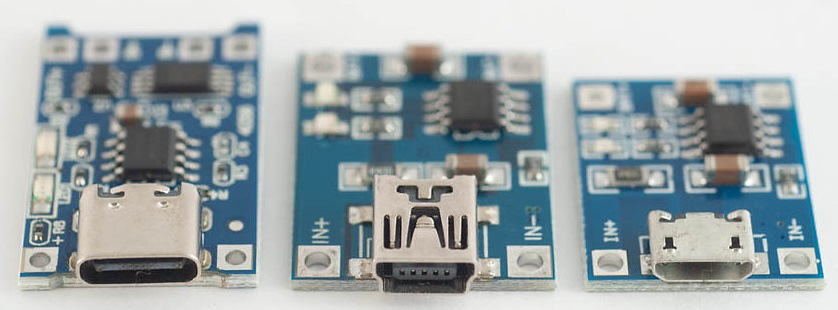
Figure 14.24 – A sample of LiPo battery chargers
These chargers can be soldered into your circuits and then charge your battery using USB-C, mini, or micro cables. Some of the circuit boards we have been using have a built-in charger too and we used a special charge board, the Adafruit LiPoly Charger BFF Add-On, for QT Py. The batteries from the wearable websites recommended in this book all have circuit protection and it is highly unlikely you will come across any of the issues mentioned. I have only had a few batteries go puffy over the course of many years, but I just disposed of them safely at a purpose-specific dump site. The temperature can also affect your battery – if it is cold, the battery may not last as long.
A Note on Alternative Power Sources
Another way to power your wearables is to use small power banks, which are easier to handle and are useful beyond building the wearable. I have seen a lot of people making the shift from unpacked LiPos to power banks in recent years. You can get these power banks with solar cells on the top, so they recharge in an environmentally friendly way too. These banks can often fit into pockets or other areas of your wearable.
You can also use alkaline batteries, which are not rechargeable. These are usually AA or AAA for wearables because of their size. Using these batteries can be a cheap way to add power and you can buy battery holders (see Figure 14.25) that have switches:
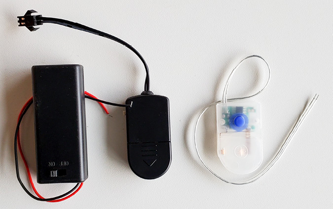
Figure 14.25 – Switched battery holders
If you use these, you’ll also have to plan for replacing the batteries. Because they need replacing, they are less friendly to the environment and will end up costing you more. You should also build an easy way to access where you have put the batteries into your wearable.
There are also many more options for solar panels to be integrated into wearables. For these, it’s good to make a battery charger circuit that will consist of your batteries, a solar panel, and a power diode. This is the 1N4001 diode we used in Chapter 6, Exploring Reactions Through Outputs, that has polarity. Electricity will only flow in one direction – toward the silver line. Think of this line as the exit line. This is placed so that the power never goes back to the solar panel.
Choose a solar panel based on the voltage and output – if it has a maximum of 100 mAh, this tells us that in good lighting conditions, the panel will output 100 mAh per hour at 6 V. If we have a battery connected to the solar panel that has a 1,100 mAh capacity, it will take 11 hours for this solar panel to charge up our battery. There are a variety of solar panels (see Figure 14.26) to choose from and here are some examples:

Figure 14.26 – Various solar panels (flexible)
Some of these are very rigid, so would suit a wearable that has a stable, large flat surface. There are flexible panels see (Figure 14.26) that would suit curved areas of the body.
To hook up a solar panel, we would connect the ground wire from the solar panel to the ground of our battery. Then, we would connect (or solder) the power side to one side of the diode. Ensure that the diode with the silver end is facing toward your battery. Solder the end of the diode to the positive wire on your battery, as shown in Figure 14.27:
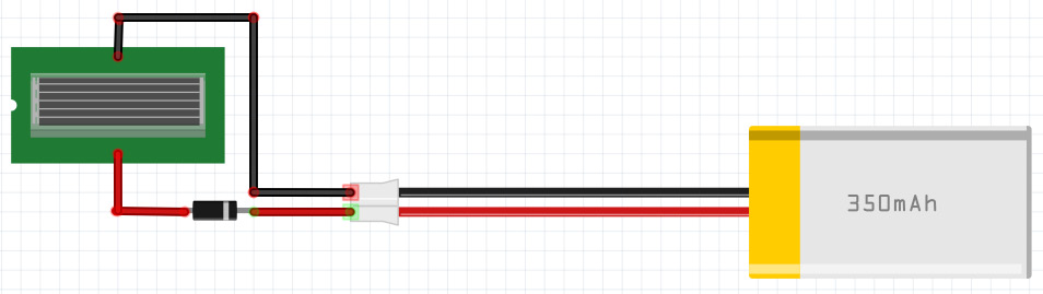
Figure 14.27 – Soldering the battery and solar panel circuit
I usually like to run mine through a charge board first (as shown earlier in Figure 14.23) to handle the charge current, as well as allow me to charge my battery with a cable during less sunny months.
Some of the solar panels come with a thin film on top to protect them, so be sure to remove this first or it won’t work. If your panel isn’t marked with + and –, then use your multimeter to check which connection is correct before you solder wires. Using a solar-powered circuit is a great way to be more ecological in your practice. Lastly, for small wearables and interesting solutions, you can find these ultra-mini solar panels (see Figure 14.28):

Figure 14.28 – A mini solar cell
The single solar can be purchased at https://www.mouser.co.uk/ProductDetail/SparkFun/PRT-09541?qs=WyAARYrbSnbrhplj7dcHPA%3D%3D. You could plan an interesting wearable where these mini solar panels become a feature of the design.
There is interesting work in the field of power and Jianliang Xiao (2021) et al. at CU Boulder have developed a low-cost wearable biological battery device. Pictured in Figure 14.29 is a thermoelectric ring:

Figure 14.29 – A thermoelectric ring (Credit: Xiao Lab)
It is stretchy, so it could be worn as a ring or a bracelet that touches the skin, using a person’s natural heat to convert that heat into electricity. It is also fully recyclable.
Lastly, you could look to add wireless induction charging capabilities to your wearable. You can buy the compatible Qi charge coils (see Figure 14.30) that you add to your power circuit to charge your battery:
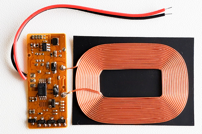
Figure 14.30 – A wireless induction coil to charge your battery
They can be expensive, so make sure it has a purpose in your project. You’ll need to plan exactly how the wearable would fit onto the base unit to charge, which the wearer would need as well. With many mobile phones now charging wirelessly, many people do prefer this way to charge their electronics, so it could be an interesting upgrade to a wearable.
After seeing some of the ways we can add power to our wearables, learning about some of the ways to troubleshoot can help you to solve some issues when making wearables.
How to troubleshoot
Sometimes, things go wrong when we are connecting our circuit hardware or programming it. As we’ve worked through the exercises, I’ve noted some things you can try to help with issues. I usually turn to forums to see whether someone has had a similar problem or issue to what I am experiencing. You’ll find that this is one of the really positive things about using the boards we’ve chosen throughout the book – they are all very well-supported. You’ll find many help documents, tutorials, resources, and support from the community.
Issues with the QT Py ESP32-S2 board
One of the ways to help solve issues with the QT Py ESP32-S2 board that I came across was that you can factory reset this board. I also didn’t realize that you can use this board as a drive, and when you press the reset button on it twice, if it’s plugged into your computer, it will appear as a drive. Figure 14.31 shows the drive when it is opened on my computer:

Figure 14.31 – Bootloader files on the QT Py ESP32-S2
If your board isn’t working how you are expecting it to, then you can upload a new bootloader. The short tutorial is available on the Adafruit site: https://learn.adafruit.com/adafruit-qt-py-esp32-s2/factory-reset#factory-reset-and-bootloader-repair-3107941-7.
The Arduino IDE
Another way we can make programming a little easier is to take advantage of some of the features in the Arduino software. Sometimes, we need to make a change in the code – maybe change a variable name or pin number:

Figure 14.32 – Selecting the x variable to change it
In this example, I needed to rename the x variable. There is a built-in feature to make this quick and accurate. If I were to miss one of the x variables in my code, then I would get an error message and the code wouldn’t work. Highlight x (see Figure 14.32) or whatever variable you want to change.
Right-click your mouse to bring up the menu (see Figure 14.33) and choose Rename Symbol from the pop-up menu:
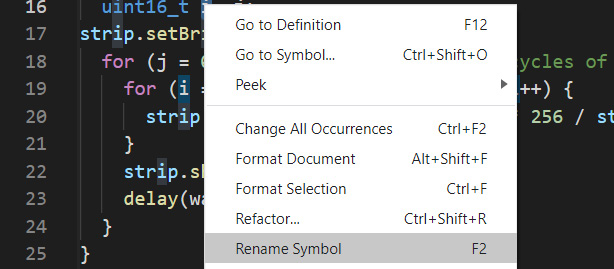
Figure 14.33 – Renaming all the variables at once with Rename Symbol
When you’ve selected Rename Symbol, it will open a little popup where you enter what you want to change it to. I’ve entered i for the new variable name, as in Figure 14.34:

Figure 14.34 – Renaming the symbol by typing in the new symbol name
Then, hit Enter on your keyboard, and it will change the occurrence of your x variable to i throughout the code.
Recognizing errors is also important so that you know how to search for help. In Figure 14.35, it shows an error message in the console:

Figure 14.35 – The Output window showing an error
The code won’t compile and it tells us in the Output message that there is an error:
expected ; before the } token
This tells us where to look in our code. So, I will look through the code for the line:
pixels.setBrightness(20)
I can see that there is a ; symbol missing from the end of the code line, so this is the problem. In Figure 14.36, when we hover over the code line with the error, it also has a popup for how we can fix this line:

Figure 14.36 – Finding the errors in our code
Make the fix and then upload the code again. Always look to Output and check what the errors are. It’s important to be able to interpret the error messages and over time, you will become familiar with certain errors and how to fix them. A lot of this will come with experience.
Sometimes with Arduino, I also open previous versions of Arduino. Trying it in another version sometimes fixes errors I may have had with libraries or installs. There are also other platforms to program Arduino, including Platform.io, which is an IDE that has a lot of extra tools such as code snippets and debugging (https://platformio.org/) and which is built on top of Visual Studio Code (https://marketplace.visualstudio.com/items?itemName=platformio.platformio-ide). This will take a little time to read through in order to get it up and running, so I wouldn’t recommend it for beginners. Once you have Arduino IDE under your belt though, it’s a platform to which many people migrate. There is also Codebender (https://codebender.cc/), which is an online editor that allows you to share code online. This does require a monthly subscription though, so you will need to evaluate the pros and cons for yourself. Lastly, Arduino itself has an online editor that you might want to try: https://create.arduino.cc/editor. You can save sketches online and you won’t need to update libraries because they will be maintained for you.
Documentation
Having good troubleshooting skills is very important. Sometimes, I’ll make a project and then I find myself saying, “that shouldn’t happen,” “why is that doing it this way?”, or “darn, it’s not working.” Sometimes, the wearable might work differently from what you intended, and sometimes, you’ll need to figure out whether it is the hardware connections or the code that has gone wrong. For all these issues, try to follow a step-by-step process.
If you can document what you did to fix the error or document what you are trying so you don’t repeat yourself, that can be a good process to do. Record your error, describe exactly what is happening and what is affected, record the results, record the data or what the output is from the code, and record what steps you’ve taken to try to solve the issue. This is also important when you are asking for help. You’ll be able to describe the issue or problem and its outputs.
Take this to a formal level – you could get a Lab Notebook, or create a page in Notion for each project you are working on. Be formal with it and write the story. For example, you might write, “this morning, the sensor still wasn’t putting out values that made sense, so I tried changing the baud rate from 9,600 to 115,200, and this didn’t fix the error. I checked that I had the correct library installed, which was DHT11, and I tried a new library, DHT11_Test. I’ve since loaded a new example file that was included with the library, test_sketch_temp.ino, and after changing the pin number to A3, I uploaded the code. This has worked. So, I need to figure out what the differences are between the code and libraries so the error won’t happen again.” It’s so easy to go in circles if you haven’t written it down. If you’re lucky enough to have a friend who also makes things, they might read it and ask you, “Why didn’t you try the DHT12 library?”, which may help you solve the issue. Lastly, if you are away from your computer or project for a few days, it is incredibly easy to forget what you tried and what failed. The notebook is a great reminder.
There are usually a few things that can fix some problems – following this list may help:
- Check your power is on.
- Check the battery is charged.
- Are there any wires touching that shouldn’t be?
- Have wires become disconnected? Check for any open circuits.
- Check that the wires are hooked up correctly. Double-check.
- The pull test – if it’s a soldered circuit, tug at the wires to be sure they aren’t only barely connected but that they have a strong connection.
- Check the polarity of components – don’t forget the diodes we’ve used need to be the correct way around.
- Does the board need a driver, library, or a board installed to work?
- Have you chosen the board and port from the Tools menu?
- Check if your USB cable is a data/sync cable and not just a charge cable.
- Is anything on the board hot?
- Check your resistor values and whether they need replacing with different values.
- Try this: upload a basic blink sketch to check your board and connections all work.
- Try resetting the board.
- Check your component datasheets, particularly the power requirements, and the pin connections.
- Check the pinout diagram of the board you are using – what are the SPI connection pin numbers?
- Start by removing one of the sensors – check whether it works with fewer components to try to eliminate the part that could be causing the issue. Add the parts back together one by one.
- Try to focus on the hardware or software individually.
- Try one then the other. If you do both at the same time (which I have done in a panic before), it is extremely difficult to find problems, and you generally make more.
- Have you tried swapping out one component for a similar one or the same one? For example, swap out an OLED for another OLED to see whether it was the one you were using.
- Is it just the environment that is making your circuit appear that it isn’t working? For example, I’ve programmed UV sensors, and they won’t work indoors where there isn’t UV, or perhaps your temperature sensor has been set for temperatures that don’t exist where you are testing your circuit.
- Lastly, take a break and come back to it with fresh eyes. You’d be surprised how often this works. Also, try telling a duck. So, I have a little toy duck, but you can use anything – when you say the problem out loud and what you’ve tried to do to fix it, it can sometimes trigger you to think of another solution or something else to try.
I used to keep a similar list printed in the front of my notebook as a process to go through in case I’ve not been able to solve a problem I’m experiencing. Over time, checking these issues will become second nature to you.
After looking through a lot of the ways we can troubleshoot our circuits, let’s change gear a little and think about the future!
What’s in the future?
You are now part of the future of wearables too! With your new making skills, you’ll join the wearable field and be able to contribute informed wearables, wearables with a purpose, to the wearable community. Hopefully, you’ll also explore alternative ways of making or using and mixing up components from other fields – for example, I’ve mashed together one of my QT Py circuit boards with these little ring terminals to create a version of the board (see Figure 14.37) that I can quickly get connected with croc clips:
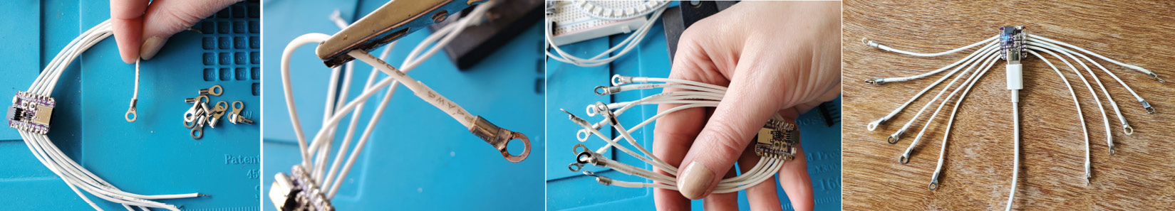
Figure 14.37 – Adding your own inventive connections to the circuit boards you use
I started by soldering wires to the circuit board. Then, I stripped the wire ends and folded them over to create good connections. I pushed heat shrink onto the wire before pushing the wire end inside the ring terminal. There, I applied a small amount of flux to help the solder flow through, and I soldered the wires to the ring terminal. I gave it a little tug to be sure there was a good connection. Then, when it has cooled (if you don’t wait for the ring end to cool, your heat shrink shrinks), slide the heat shrink over the end. Shrink into place and enjoy!
Get inventive and explore – there is no right or wrong way to do things.
We’ve seen many projects and research outputs throughout this book, as examples of how sensors are used, what creations people are making, or topics that are being explored to create a wider dialog – but where is the field of wearables headed? Some of the key themes I’ve been seeing in the wearable field include work on sourcing power for wearables and a continued effort in medical wearables, but what else is there?
Current literature discusses the benefits of wearable technology. We see themes of social benefits, medical purposes, increased self-awareness, and sometimes behavior change. These positive aspects I see continuing, and hopefully, future materials and techniques will reinforce the current good practice being done. One final note – you might find a fair in your area where you can try and sample new materials. Here’s one example of an event that showcases new and exciting materials: https://techtextil.messefrankfurt.com/frankfurt/en.html.
Materials
I find stretchy electronics very fascinating. New and unusual materials are becoming available to produce sensors such as this wireless tag (see Figure 14.38) with a stretchable sensor and antenna:
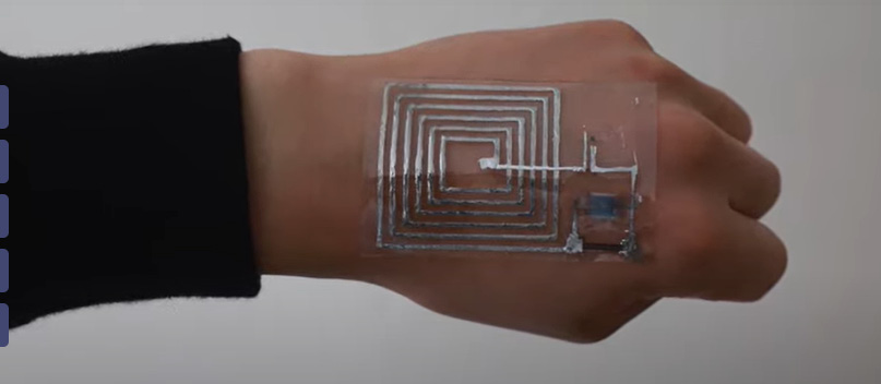
Figure 14.38 – A stretchy tag on skin
This is a collaboration of a team of engineers from Stanford University and Keio University in Tokyo and their research is presented in their paper: https://www.nature.com/articles/nature25494. Because it is soft, it behaves similarly to skin. These types of wearables will likely become more common as their usefulness increases. There are possible applications in the fields of medicine or caring for the elderly, but I could see an application for any place where scanning was needed, for work or safety scenarios. There is also research for clothing for personal thermoregulation, which involves bendable smart clothes that adapt how they use thermal insulation functionality. It mimics pores in human skin – see Zhong, Y., Zhang, et al. (2017). Would this technology become widely used and applied for other wearables?
Along with new materials, there are possibilities with coatings. Purdue engineers have developed a new spray-coating or sewing method that can alter conventional fabric items into battery-free wearables that can be washed in a washing machine. “By spray-coating smart clothes with highly hydrophobic molecules, we are able to render them repellent to water, oil and mud”, said Ramses Martinez. “These smart clothes are almost impossible to stain and can be used underwater and washed in conventional washing machines without damaging the electronic components sewn on their surface.” You can see and hear more at https://youtu.be/gQ0TCLXZ6Q8.
The material aspects could also move us toward researching and working with protective gear and body enhancements. Do these wearables become a second skin, and if so, what would the requirements be for this? There could be medical applications and uses for this, as well as support for certain occupations. Room for a hybrid design of spray and thin material that can be applied directly to the skin could be an interesting direction – provided the context and purpose are clearly defined.
Lastly, materials could also involve the way we make materials. Experimenting with reuse, recycling, and repurposing should play an essential role in the fashion and electronics industries moving forward. How do we incorporate these principles into our own prototypes? Harvesting components should also be a skill we try to learn as e-waste becomes prolific in our landscapes. Does reusing components and elements of other circuits play an essential role in developing innovative wearables?
The body
I hope we see new takes on body-centered wearable technologies, particularly ones that aim to improve the wearers’ quality of life. We are starting to see themes of Fashion takes Care, and I hope this theme continues through to the wearable community. This could include more research and experimentation with e-tattoos – electronic ink being printed on someone’s skin or embedded within it. This could be to create integrated circuits. How would this be a seamless embedding with their skin? What purpose could this have? Creating e-tattoos could offer a low-maintenance solution to wearables too. Could these solutions coordinate with the research on generating power through movement, so these wearables would require no external power sources? Creating a device that was printed on the skin would also allow for immediate responses through the electronics – could it be implemented for safety features?
Is the body-centered theme carried to injectable devices? These are devices that are inserted into a person’s body, usually for an extended amount of time. They usually remain at the skin surface level. If we continue to make technology smaller, we might see more implant technology being used. These miniature devices are currently used particularly as RFID devices, but can we continue to push this further? Possible issues could be the comfort in terms of placement and size and also security issues – would this be used to track wearers and would we feel comfortable with technology on us all day and night? Similar to the injectable are digestible wearables. These include pills with electronics that are used to diagnose issues internally. This could help with medical diagnosis, as they are currently being used, but what could the future hold for these types of devices? They need to be made from biocompatible materials so there is no harm to the person.
This leads me to think about natural interfaces and ways of communicating. Combining e-tattoos with ways of sensing our gestures could be a way forward with wearables. Using less obtrusive designs could mean that exploring implicit interaction, or passive interfaces, becomes a natural progression within wearable technology.
Environments
A leap into interesting technology could be bio-culture – do we grow wearables? Do we see organic materials, renewable sources, or wearables growing with us as a step to more environmentally conscious designs of systems? Research on mycelium has been conducted into the uses of this incredible root communication structure. Mycelium, with its massive branching underground structures, has been used to create furniture prototypes, hats, and packaging from this same structure. Can we combine electronics with it to create new and exciting materials and purposes?
A mix of real and virtual environments is likely to be a direction that wearables take us in. I had an email from a company describing a new suit they had developed. It was a full-body suit that they were testing for gamers. It responded to the virtual environment through sensors and motors. After reading this, it was revealed that it was an April Fool’s Day joke – however, these are not such futuristic or far-off technologies. The only surprising thing is that this is not already a current product. Some interesting artistic projects pushing these boundaries include Janne Kummer working on https://www.jannenorakummer.de/projects-8 and https://www.jannenorakummer.de/leakingbody; a current research project at HAW Hamburg, https://www.haw-hamburg.de/en/research/research-projects/project/project/show/klima-act/; and lastly, the student Anastasia Almosova who has built impressive 3D virtual journeys that are guided by wearables – https://anastasiaalmosova.com/Interface.
Even taking one step removed from this, the prospect of creating a wearable that allows the wearer to interact in a meaningful way with their environment is an interesting direction. Are there sensors, monitors, or technology in an environment, inside or out, that respond and interact with an item we are wearing? Is the garment controlling our environment – for example, is it monitoring the air quality in our offices and adjusting it if our clothing monitors that pollution levels are too high? It’s worth noting how artificial intelligence (AI) might also have a role in the future of wearables. We are already seeing shops that track us when we simply take what we want from the shelves and leave – how would certain wearables be used in the context of AI? Does a relationship with technology alter our perception of wearables? Is it a luxury or does it become more ubiquitous and necessary in daily life? Does it all just become about consumer habits and what happens with our data? Who will own it? Do the wearables revolt and become beacons that break technology nearby, stopping or scrambling cameras, circuits, and signals? Do we use the wearables to notify us of these surveillance activities?
We’ve touched on the essence of culture-driven wearables and hyper-body systems and these are areas that warrant further exploration. Integrating our culture, innovation, and ethos into the wearables we make to support and enhance society or societal living should be a focus for wearable designers. Through learning about society, we can use this to inform the designs, creating far more useful and valuable wearable technologies. Alongside this, creating wearables that focus on and use more than one part of the body could give us a better understanding of the value that wearables can have for the wearer. We can create a sensual, meaningful, involved experience for wearers.
Lastly, I want to end on a fun note! Often people use wearables, for example, as step counters, because they consider it fun to meet challenges, even if they are set by themselves. Fun, enjoyment, and pleasure are important parts of the human spirit. There is a lot of research in the field of Funology, (Monk, A., Hassenzahl, M., Blythe, M., & Reed, D., 2002), and the enjoyment of designing should never be discounted.
Even when designing serious wearables, it is important to give the wearer moments of delight and little sparks of magic and make their experiences enjoyable. Not only that but innovative wearables should also be fun, creative, and exploratory to make. Ideas, exploring, creativity, and imagination are all important parts of the development phase.
Summary
Congratulations! You have now finished the book.
I hope you have found it an inspiring and, at times, challenging journey. You will be equipped to design sewable circuits using conductive fabrics and threads, as well as create circuits with sensors and outputs. You also worked to create a smart wearable using IoT for connecting to an online service with an ESP32-based board. Hopefully, you’ll be carrying around a small multimeter with you as you hunt for metallic fabrics.
You have followed a Design Innovation process and now have the tools to design your projects. There are templates and guides, along with questions to ask yourself when creating in this field.
This final chapter has links and references to other programs and applications you might want to try. It could be that you start to create your schematics in Fritzing or that you look at circuit design in Eagle. Whatever direction you decide to head in, remember that there are many support forums, tutorials, and guides online. The wearable community is welcoming and helpful, so hopefully, you will become someone who can help and guide those new to the field too. Thanks for following along on this journey and I hope you’ve had as much fun as I have.
References
The following references were referred to in this chapter or are suggested for further knowledge about the topics presented:
Ren, W., Sun, Y., Zhao, D., Aili, A., Zhang, S., Shi, C., ... & Yang, R. (2021). High-performance wearable thermoelectric generator with self-healing, recycling, and Lego-like reconfiguring capabilities. In Science advances, 7(7), eabe0586. https://www.science.org/doi/10.1126/sciadv.abe0586
Matsuhisa, N., Niu, S., O’Neill, S. J., Kang, J., Ochiai, Y., Katsumata, T., ... & Bao, Z. (2021). High-frequency and intrinsically stretchable polymer diodes. In Nature, 600(7888), 246-252.
de Medeiros, M. S., Goswami, D., Chanci, D., Moreno, C., & Martinez, R. V. (2021). Washable, breathable, and stretchable e-textiles wirelessly powered by omniphobic silk-based coils. In Nano Energy, 87, 106155. https://www.researchgate.net/profile/Debkalpa-Goswami/publication/351824432_Supporting_Information_Washable_Breathable_and_Stretchable_e-Textiles_Wirelessly_Powered_by_Omniphobic_Silk-based_Coils/data/60ac00f592851ca9dce1d6a2/2021-OSC-Supporting-Information.pdf
Zhong, Y., Zhang, F., Wang, M., Gardner, C. J., Kim, G., Liu, Y., ... & Chen, R. (2017). Reversible Humidity Sensitive Clothing for Personal Thermoregulation. In Scientific reports, 7(1), 1-8. https://www.nature.com/articles/srep44208
Monk, A., Hassenzahl, M., Blythe, M., & Reed, D. (2002, April). Funology: designing enjoyment. In CHI’02 extended abstracts on human factors in computing systems, (pp. 924-925).
Blythe, M. A., Overbeeke, K., Monk, A. F., & Wright, P. C. (Eds.). (2004). Funology: from usability to enjoyment. Dordrecht: Springer Netherlands.
Wright, P., McCarthy, J., & Meekison, L. (2003). Making sense of experience. In Funology (pp. 43-53). Springer, Dordrecht.
McCarthy, J., & Wright, P. (2004). Technology as experience. interactions, 11(5), 42-43.
McCarthy, J., & Wright, P. (2018). The enchantments of technology. In Funology 2 (pp. 359-373). Springer, Cham.
Dodgson, M., Gann, D., & Salter, A. (2005). Think, play, do: Technology, innovation, and organization. OUP Oxford.
Review questions
- What are the benefits of documenting our projects?
- Name three possible good ways you can troubleshoot your circuits.
- What are some of the techniques we can use to bring other dimensions into our wearable designs?
- Reflect on your learning throughout the book. What activities did you find the most helpful or useful for your wearable designs?
- What next steps will you take to create wearable technology?
- What does the future of wearables look like to you?