
13
Implementing the Best Solutions for Creating Your Own Wearable
The skills that you’ve been practicing throughout the book feel like pieces of knowledge you’ve earned and this chapter is a little like the final piece in the puzzle. You’ve worked through a journey of activities (over 50) to get to this point and as you work through the iterations of Message Bag, it will provide you with a complete skill set to create your own wearables. Although you are continuing your wearable journey using Message Bag, you should start to think about parallels in how you will implement these techniques into your own future wearable designs.
In this chapter, you will look at making decisions for iterations in an early prototype version of a wearable, and we will upcycle and complete the Message Bag prototype we started in the previous chapter. We’ll also take a sneak peek at even more potential upgrades, which we don’t necessarily have to implement, but it’s important to learn to push and iterate your designs. I feel like I’m always pushing to learn more in this exciting field and you will see how the wearables we create can be improved, revised, and upgraded over time.
By the end of this chapter, you will have come full circle on your journey and created a wearable near-body system with iterations, soldered and sewn it into place, and started planning for your own wearable design.
In this chapter, we’re going to cover the following topics:
- A template for design
- Upcycling your own Message Bag
- Upgrades for the ambitious using IoT
- Use it or do something else
Technical requirements
In this chapter, we will create an iterated prototype of Message Bag – therefore, we need the prototype created from the previous chapter. We will also look at activities that use the following:
- Arduino software as the IDE and access to https://io.adafruit.com/
- The Adafruit QT Py ESP32-S2 or the Adafruit QT Py ESP32-C3
You will need your prototype from the previous chapter, which was made with the following:
- Adafruit QT Py - SAMD21 Dev Board with STEMMA QT
- An RFID reader: Mifare RC522 with five corresponding tags
- Sewable Flora NeoPixels and a Flora Sewable 3-Pin JST Wiring Adapter
- Adafruit LiPoly Charger BFF Add-On for QT Py and a rechargeable battery, with 3.7V and a 2-pin JST-PH connector
A template for design
Working through this chapter, we will create iterations to improve on our Message Bag design from the previous chapter. To be able to do this, we’ll look at what observations we made and how those affect the use of the system. This is an essential step in the process of creating a wearable. Before we do that, let’s create our template for design based on some of what we have learned throughout the book. You will be able to use this template to help form the ideas for the wearable you want to create and the purpose behind it.
Activity 13.1 – Creating the road map for your wearable Project
Making wearables is fun! There are often many approaches to creating a wearable and through the activities in the book, we’ve taken a very hands-on, learning-through-doing style, and learned about a Design Innovation way of making a wearable. We can create a road map for the wearable we want to make for our different goals. If you’re looking to continue your learning and exploring, then you might want to do your project planning based on the components you have.
A component-based project plan
Your planning may look similar to the following:
- What components or microcontroller do I want to use in my wearable?
I have a Gemma M0, an OLED screen, NeoPixels, and a motor. I’ll decide on a sensor to buy to have input for the system.
- What part of the body do I want to prototype for?
The ankle and foot area (choose a new body part to learn different skill sets to be able to make a wearable comfortable to fit that body part, jewelry style, or off-body shape.)
- What features make this wearable a useful item and who is it useful for?
I’ll research topics related to mobility and health. There could be an application in relation to gait and walking.
You can refer to Chapter 1, Introduction to the World of Wearables, for an illustration (see Figure 1.17) of possible body placement locations. Additionally, Chapter 8, Learning How to Prototype and Make Electronics Wearable, has the information you should refer to for planning out your wearable. In particular, we talked about comfort, usability, and style universe. These questions can help you form a starting position for your wearable. Planning is an exciting process. Put these ideas in a notebook – or a page on Notion, for example, (https://www.notion.so/) – so you can add links to resources that you find or even sample code to help you get started.
A topic-based project plan
Your planning may look similar to the following:
- What topics interest me?
I’m interested in exploring nature as a theme. Maybe more about awareness of our environment. This might have sensors or communicate about environmental issues.
- What goals would I like the wearable to have?
I’d like the wearable to let people experience nature in alternative ways – to highlight what they might not have noticed before, or the unseen. This might be information about our air quality, for example. How can I make it visible?
This could use light as the output and maybe an air quality sensor for the input to get data from the air around us. I’d need a circuit board with I2C connection and at least 1 pin for NeoPixels.
For either of these two starting project positions, you’ll need to read about the domain – what the context for your wearable is. With research and information about that area, you’ll be able to create a more effective and interesting item. Additionally, find people to speak with about this topic to discover how they are affected, and what their stories or usage are. Often, learning useful information can be carried out by making observations. After collecting this information, think about what this data and information tells us. What are the insights from speaking with people?
Looking into what solutions have been tried or made previously, what worked what was successful, or what is missing in this area is an important step for consideration. Now that we’ve had a brief look at setting our road maps, let’s return to our previous case study of Message Bag.
Upcycling your own Message Bag
When we ended the previous chapter, you may have collected some information for improvements to the use of Message Bag. What it currently does is follow a process with four stages, including an initial sequence of lights to communicate that it is on, a scan-in or scan-out of a tag, checking the state of the tag and whether it is scanned or not, and then a response based on the state of the tag.
When using this prototype, although it functions well, there are a few issues you may have noticed. These iterations are related to the function or role of the prototype, not the aesthetics or look and feel. We can implement these iterations while it is still breadboarded.
For example, in the instances when there is a slight delay in the tag scanning process, I’m left confused. Is the tag recognized? Is it still scanning? Secondly, when the system is powered off and back on again, the tags I scanned are not recorded.
Did you also make these observations? Feedback to communicate when an item is being scanned would be a good improvement, as would using non-volatile memory to store the state of the tags. Non-volatile memory is retained even if the system is powered down.
A new plan for the functionality of Message Bag could be described in the following steps:
- Turn on the system.
- There should be an initial sequence of lights to inform the wearer it is working. This is positive feedback from the system to communicate to the person that the system is functioning.
- The lights will illuminate according to the last use scenario. The circuit reads the stored tags from the last time it was used.
- Depending on the tag information stored in memory, it will light the corresponding lights.
- Scan in or scan out. Hold the item tag to the RFID reader.
- Lights confirm that it is scanning.
- The tag state is encoded to memory to scan in or out. If the item is not yet scanned, this means the item is being put in a bag. So, it will scan it in. If the item has been scanned, it means they are removing the item.
- The on/off light responds to the tag being scanned in or out of the system.
Now that we have a plan of what we would like to implement to make this a more effective prototype, let’s implement the first change.
Activity 13.2 – Iterations on Message Bag for communication
This activity involves implementing a light sequence that will happen when the tag is scanned, to allow for positive feedback from the system. This way, the wearer knows that their tag is being scanned. I’ve posted the code for this exercise here: https://github.com/cmoz/Ultimate/tree/main/C13/Activity13_2Iterations.
Open and look at the code. In loop(), as it waits for tags to be scanned, the while (getID()) function runs. We’ll add the following:
rainbowEffect(1, 1);
This will run the rainbowEffect() function once. This will improve our circuit because the rainbow sequence displays when a tag is scanned in or out. Look a little further into the code. In the function definition that sets the color for our scanned NeoPixels, void setNeoColor(), at the end of this function, we call checkAllOn(). Let’s look through this function’s declaration.
The purpose of this is so that if all the tags were scanned in, this indicates to the wearer that all the corresponding items have been packed. We want to reward this with a positive light sequence. The rainbow sequence plays several times after the last tag is scanned and this happens because of the rainbowEffect(3,5) code.
Continue to look at void checkAllOn() – we use && as a Boolean operator to evaluate conditions. This logical AND decides that only if this condition is true (&&) and this condition is true, then we play the rainbow effect.
The Boolean operator, &&, returns true if all the conditions are true. In this code, that is possible with this line of code – if ((redTag == true) && (purpleTag == true) && ( yellowTag == true):
void checkAllOn() {
  if ((redTag == true) && (purpleTag == true) && (
        yellowTag == true) && (greenTag == true) && (blueTag == true)) {
    rainbowEffect(3, 5);
  }
  if ((redTag == false) && (purpleTag == false) && (
        yellowTag == false) && (greenTag == false) && (blueTag == false)) {
    theaterChase(strip.Color(  0,   110, 127), 100);
  }
}
We’ve also added another if statement, so that if all the tags have not been scanned in, there is a pale blue light sequence to communicate to the person that there are no scanned tags, or all tags are out of the bag. This plays a sequence that is called theaterChase() and we added a strip.fill((0, 110, 255), 0) line of code at the end of the function because we want the lights to stay on, as pale blue, so the wearer knows that the bag is working and it’s waiting for a tag to be scanned.
Our aim as makers of wearables is to help the wearer as much as possible. We want them to achieve their goals in as easy a way as possible. These changes should help us with that! Now that we’ve amended the code for the light responses, we should look at storing the tag state in memory so that they keep the same state as when they last scanned it. This is the next activity.
Activity 13.3 – Storing variables in non-volatile memory
The QT Py SAMD21 board has 256 KB of flash for storage. If your sketches need more, there is an additional chip you can buy to solder more memory – it’s similar to adding a 2MB SSD drive. After soldering this memory, it is accessible through SPI flash using Arduino on SPI1 and a chip select pin (CS) 17 – there is sample code as part of the Adafruit SPIFlash library. However, 256 KB flash is enough for us.
Storing data on the microcontrollers that we’ve been using is done through a version of EEPROM memory. EEPROM is electrically erasable, programmable, read-only memory. Flash is an offshoot of EEPROM and the differences are in the way they access and erase the memory – byte-wise for EEPROM or block-wise for Flash. We can erase the bytes and reprogram them. It’s used for small amounts of data. We don’t need to go into too much detail here about memory, but we do need to use a library to help us to write to it. Because the board we are using isn’t compatible with the Arduino ATMEL-based library to store using EEPROM, we can use a different library to store data into flash memory on the ATSAMD21 and ATSAMD51 processor families that our QT Py SAMD21 uses. There is a FlashAsEEPROM.h library that can be used if you are familiar with the EEPROM library and have used it for Arduino boards. This is also an EEPROM emulation library for these processors.
We will be using the FlashStorage library. It provides us with the implementation to store and retrieve data, and in this case, it’s the tag state we want to record. We will write to the non-volatile flash memory on the QT Py SAMD21. Using the Library Manager in Arduino, search for FlashStorage by Arduino. It might already be installed, but if it isn’t – install it.
Using Flash Memory
One note about flash memory is that it has a limited number of cycles on the same flash block for writing, which is around 10,000 write calls. After that, it may start to degrade.
Let’s look through how to implement the code after we have added the FlashStorage library. The code is here: https://github.com/cmoz/Ultimate/tree/main/C13/Activity13_3FlashStorage.
First, as you’ll have seen in several examples already, we include the library in a declaration at the start of our code – this is done with #include <FlashStorage.h>. Then, we declare a global object, called FlashStorage, for each data item we want to store in memory. Because we’ve used versions of variables for the color tags already, I opted for naming the variable my_flash_store with an appending initial – R for red, P for purple, and so on – for the color of the tag and NeoPixel.
A global object or global variable is declared before setup(), which allows it to be used throughout our program. The FlashStorage(my_flash_storeR, bool); code snippet is telling the program to create FlashStorage with a bool variable called my_flash_storeR. We create one of these storage areas for each of our RFID tags:
FlashStorage(my_flash_storeR, bool);
FlashStorage(my_flash_storeP, bool);
FlashStorage(my_flash_storeY, bool);
FlashStorage(my_flash_storeG, bool);
FlashStorage(my_flash_storeB, bool);
Once the program loads and runs void setup(), we want the program to retrieve the values stored in the memory. We can read and retrieve the tag state using the redTag = my_flash_storeR.read() code. This allocates the values held in that memory space to each bool variable – for example, bool redTag is created. I’ve then added Serial.println(redTag) for each tag so I can see the values in the serial monitor to troubleshoot if these aren’t correct. The setNeoColor() function will then run and depending on the bool values from the flash storage, the corresponding light for that tag will be on or off:
  redTag = my_flash_storeR.read();
  purpleTag = my_flash_storeP.read();
  yellowTag = my_flash_storeY.read();
  greenTag = my_flash_storeG.read();
  blueTag = my_flash_storeB.read();
This all happens as we start our program. The setup is complete and the system is ready for use. We need to write the tag state as we scan the tags. The tagActions() function is called when the tag has been scanned and the UID of the tag is known. After, we flip the bool for the tag to true or false depending on whether it has been scanned already. That’s when we write the value or state of the tag to memory using my_flash_storeR.write(redTag):
void tagActions(char tag) {
  switch (tag) {
    case ('0'):
      Serial.println("red tag");
      redTag ^= true;
      my_flash_storeR.write(redTag);
      Serial.println(redTag);
      break;
    case ('1'):
      Serial.println("yellow tag");
      yellowTag ^= true;
      my_flash_storeY.write(yellowTag);
      Serial.println(yellowTag);
      break;
The code snippet is a portion of our switch case control structure and we have included the code to write the tag value for all five of our tags. Now that we have had a look through the code, upload it to your QT Py SAMD and try it for yourself.
You’ll see that when you turn off the power for your board, when you turn it back on again, the lights will light up the same way you left them. This is now a useful circuit for the wearer. With the code explained and uploaded, we should fully integrate it into our bag. Before integrating it (and committing it to solder and sewing), do a final check that your connections work (see Figure 13.1):
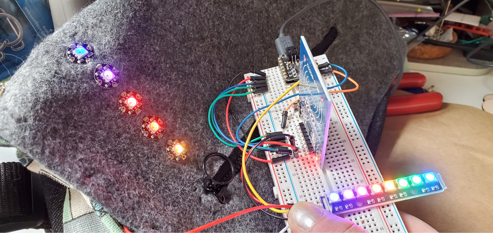
Figure 13.1 – The final test of our connections
All the lights should be working and although we can edit the code after we’ve soldered it, it’s better to check that we are correct now to avoid a mistake.
Activity 13.4 – Integrating your circuit
Earlier, we created a prototype on a breadboard, essentially making an implementation with some aspects of a role prototype. This activity will transform that prototype into an integration prototype because it will involve the role, implementation, and look-and-feel aspects. Let’s start by soldering the circuit to make it more permanent.
Soldering the components for placement
Now that we know our code and components are tested and working, we will make it permanent, durable, and wearable! We’re going to start by soldering the wires to our RFID reader. We’re starting here because it will be the easiest step:
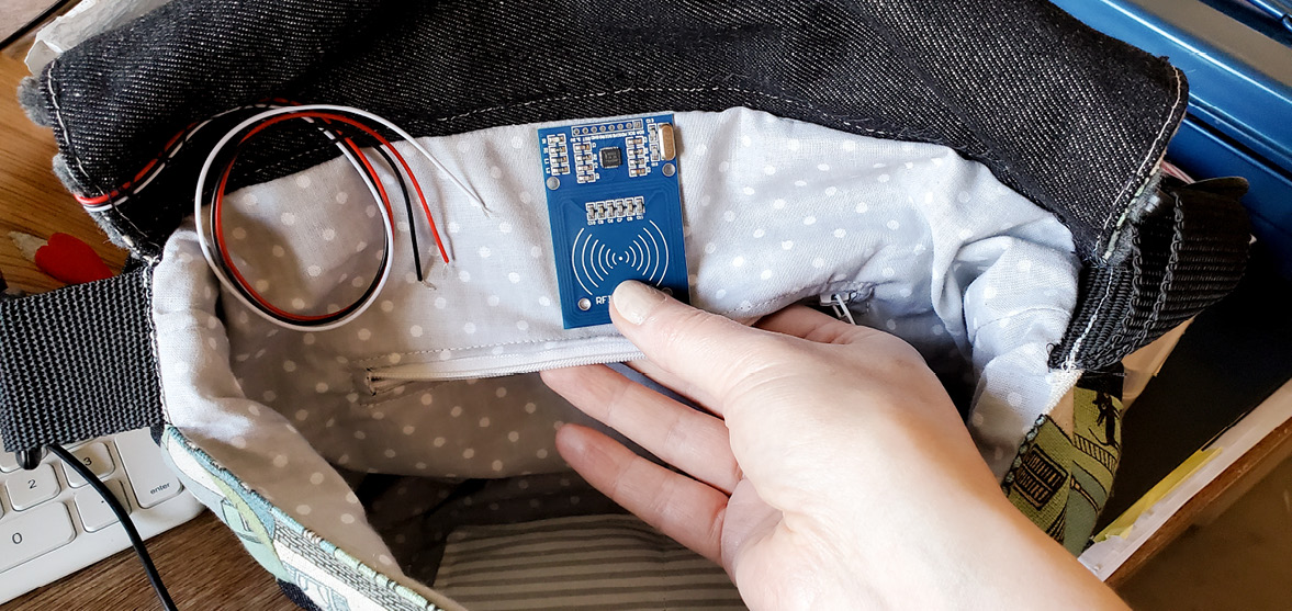
Figure 13.2 – Planning the RFID reader placement
To start with, hold your RFID board in place – mine is going inside the bag (see Figure 13.2) – and measure wire lengths to reach your circuit board. I’m taking advantage of the pocket inside the bag and I’ll cut through it carefully so I can put the RFID reader behind the fabric. Do you have a feature such as a seam or pocket that you can use to modify the bag?
After you’ve planned where the RFID board will go, we need one wire for each of the following connections:
- Ground and power
- The SPI interface: SDA, SCK, MOSI, and MISO (and reset)
That makes seven connections. Add a little more wire to your measurements just in case. Cut seven wires. Sometimes, with folds of fabric, it can make our measurements slightly off when we come to sew or solder the connection:
- I’ll start by soldering the RFID board wires. I always solder with the easiest-to-identify connections, so in this case, I’m soldering the ground and then the power wires. Strip the end of one side of your wires and make sure the wire won’t fray by giving them a little twist. Push them through the circuit board, one wire into the GND and one wire into the 3.3V hole. Solder in place (see Figure 13.3):
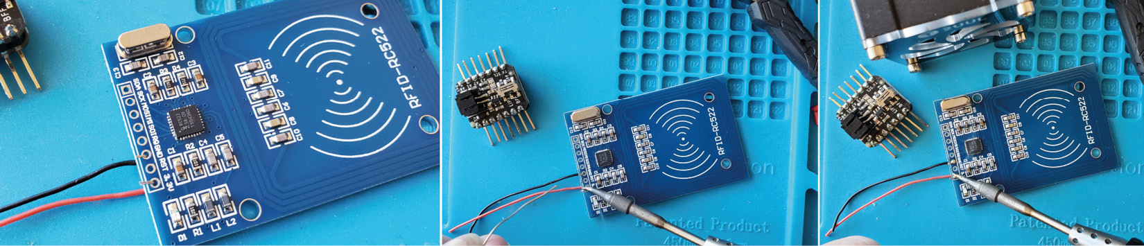
Figure 13.3 – Soldering the ground and power connections on the RFID reader
- Continue soldering the other wires (for the SPI connections) to your RFID board. If you look at Figure 13.4, at the top of the photo is a small USB-powered fan. This is helpful for soldering, as it pulls the fumes away from you. This can be a really good idea if you’re soldering at your desk!
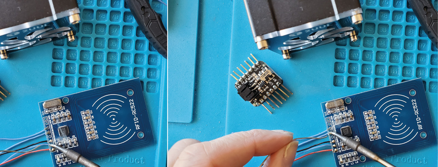
Figure 13.4 – Soldering the other wires (SPI) to the RFID board
- After all the wires are soldered to the RFID board, strip the ends off them in preparation for soldering our connections to the QT Py SAMD board.
- Straighten the pin legs as we’ve done previously (see Figure 13.5). Once straightened out, we will solder the wires to them. To do that, we need to prepare the wires and board:
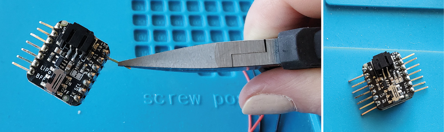
Figure 13.5 – Straightening the pin legs
- To start, let’s tin the wire ends that we stripped. To tin them means that we are going to add a little solder to the wires to coat them (see Figure 13.6). This will make it easier to solder to the pin legs on the QT Py SAMD. Also, add solder (tin) to the legs on your circuit board. Only apply a thin amount. By applying a thin layer of solder to both surfaces we want to join, it helps the solder to flow more easily between them, creating a good connection:

Figure 13.6 – Tinning the wires and circuit board pin legs
- Don’t solder power and ground just yet, as these pins need more than one wire! We have power and ground going to the RFID reader and to the NeoPixels, so we’ll do them a little later.
With the wires and circuit board tinned and ready for soldering, solder one wire at a time and double-check the connection is correct. After you solder, do the pull test to check whether it is a solid connection. I’ve also added heat shrink on the wire that I’ll slide over the top of the leg once it is soldered. See Figure 13.7, which details this process:

Figure 13.7 – Soldering to the circuit board and using shrink wrap on the connections
- Because ground and power will have two connections, it can be easier to solder a wire to the board first, then connect the other two wires to that connection. Let’s start by soldering a wire to the circuit board, one for ground and one for power.
Start by stripping the two wires, then tin them. Solder each (power and then ground) to the circuit board legs (3.3 V and ground) and put shrink wrap over the connections. Then, we need to solder the wires for the NeoPixels that we’ve sewn on the bag.
- Make a hole in your bag – if it has a pocket, that works well for hiding the circuit (see Figure 13.8). Using seam rippers, gently push them between where there is a seam edge. Break a few of the threads with seam rippers to create a hole large enough to push your RFID reader into:

Figure 13.8 – Using seam rippers to create an opening for the RFID reader
- With the components in place, slide the heat shrink over the ground and power wire. Then, take the three power wires (one from the circuit board, one from the NeoPixels, and one from the RFID reader) and twist them together. Solder these together. Figure 13.9 shows the crocodile clip part of my helping-hand solder station holding the three wires together for me so I can solder them. It is a lot easier if you can clamp the three wires together and then twist them. Make sure the solder gets through all three wires so that you make a solid connection. It will help a lot if you use flux for this join. Pull the heat shrink over the soldered joint. Be sure to let it cool first or it will start shrinking:
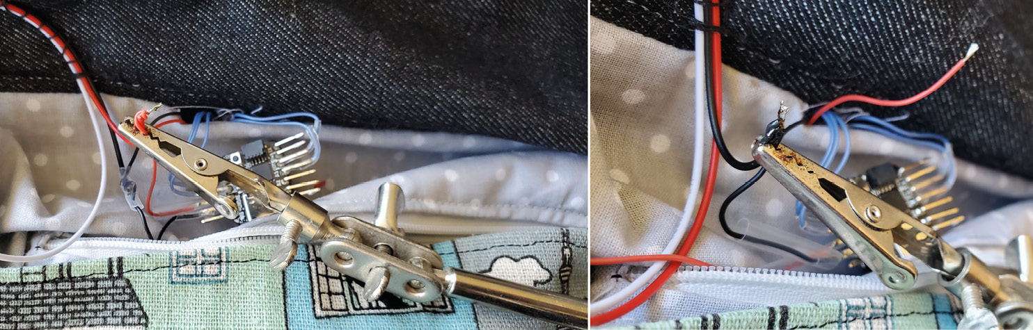
Figure 13.9 – Clamping the three wires for the power together to solder them and doing the same for the ground
- Now, do the same for the ground wires – slide the heat shrink over the ground wire coming from the circuit board and twist all three ground wires together. Solder the three ground wires together. Then, slide the heat shrink up over the solder joint. Heat it to shrink in place.
- Lastly, solder the NeoPixel data wire to pin A1.
You should now have a soldered circuit board, NeoPixels, and the RFID reader. Plug it in and test it before we sew it in place and close the hole we made. If it works, we can start to sew it in place. Put the RFID board into the hole you made earlier and place the QT Py SAMD outside of this.
We need access to our charge board – it has an on/off switch. A future improvement could be that you add a switch outside the bag somewhere and hide all the technology (see Figure 13.10):
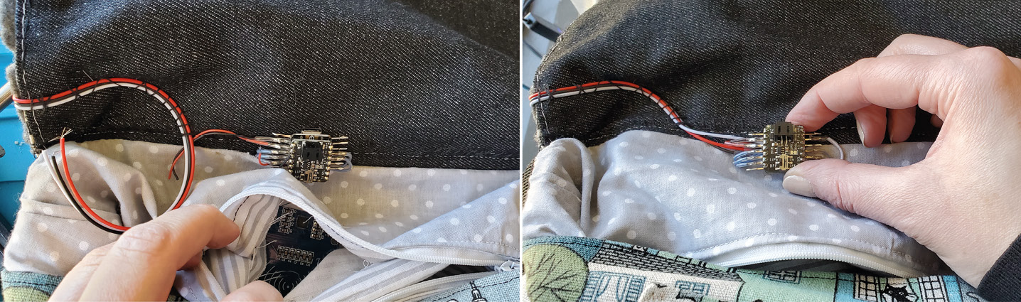
Figure 13.10 – Placing your soldered circuit in the bag
If it isn’t working, see the following:
- Check each connection that you soldered. Wires might have come loose or maybe it doesn’t have a solid connection. You can resolder it.
- Make sure you don’t have any frayed wires touching the wire next to it – that can cause a short.
- Check your pins and wires are going to the correct circuit parts. For example, the MISO pin on the RFID board connects to the MISO pin on your circuit board.
- You can also check for loose threads on your sewable NeoPixels.
- Have you powered your circuit and does your battery have enough power for it?
Once it’s working, thread a needle, and with your board in position, sew the legs to the bag to secure it in place. I’ve added some neoprene fabric to hide the legs that are showing. I cut a square and then cut a + shape in the center of the neoprene, folding the + part back to push the circuit board through the gap this made. Then, I stitched around the board (see Figure 13.11):
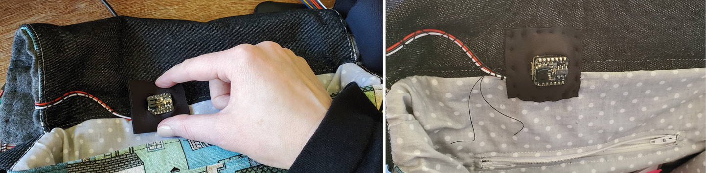
Figure 13.11 – Stitching neoprene (or fabric) around the board to hide the legs and our soldering
- Finished (see Figure 13.12)! You should plug your battery in and make a small pocket for it. Plug it in and try your new wearable! If it’s all working, you just need to close the holes we created when we were putting the components in place. So, I’ll sew up the pocket and you might have a seam or pocket to sew back together:

Figure 13.12 – A completed Message Bag with NeoPixels, an RFID reader, and the QT Py SAMD21
Well done, you’ve completed the process from Design Innovation to the creation of a wearable with a purpose! Hopefully, this meets the wearer’s goals and needs. Through testing is when you would be able to find out more information about iterating our design. I have a few ideas on ways this could become even more interesting – you might want to look at upgrades using the Internet of Things (IoT).
Upgrades for the ambitious using IoT
Now that we’ve implemented the best solutions for creating this wearable and iterated to a prototype that has more features, including giving the wearer better information on the system state, we can look at features we may want to bring to future devices.
Often when I make a project that I really like, there are ways to improve or future-proof it, and this can involve switching to a different circuit board. Some of my earliest projects started on an Arduino Uno board, which is a lot larger than the boards we’ve been using. This meant that the wearable projects I made had a more cumbersome implementation or used more space than I would want for a prototype. When creating a proof-of-concept prototype, a larger board such as the Arduino Uno is perfectly acceptable, and we’ve seen in Chapter 8, Learning How to Prototype and Make Electronic Wearable, that using this board alongside 3D printer pens and TPU is a fun, inexpensive, and quick way to prototype initial ideas. Keep in mind that you can’t solder to an Uno and it is a prototyping board, not a final implementation one. When I want to start to refine and iterate a prototype, it often involves choosing a more appropriate microcontroller board for the purpose. This is part of implementing the best solutions.
Modifying the prototype with the QT Py ESP32-S2
There may be instances of using Message Bag when we want a record of all the scanning in and out that we’ve done. This is where involving IoT integration can help us out. We did some activities with ESP32 development boards in Chapter 7, Moving Forward With Circuit Design Using ESP32, where we learned about its Wi-Fi capabilities. We also looked at a tiny-sized board, the QT Py ESP32-S2, in Chapter 9, Designing and Prototyping Your Own Hyper-Body System, which is the board we will use for the next activity. Before we can add the IoT capabilities, we should upload our current code – with modifications. So, let’s grab our QT Py ESP32 and dive in.
Activity 13.5 – Using EEPROM.h for memory access
Time to experiment with extending implementations with a board that has more capabilities than the one we were using. Open Arduino, plug in the QT Py ESP32-S2, and select your board and port. When we compile our code using the verify button, you’ll see that there is an error message:
WARNING: library FlashStorage claims to run on samd architecture(s) and may be incompatible with your current board which runs on esp32 architecture(s).
Reading this message tells us that it won’t compile for the ESP32, so we need to change our FlashStorage library, because that library is made for the SAMD architecture. If we look up this error online, you’ll see that the ESP32 can use the EEPROM library, so we can implement code that performs the same functionality after making a few modifications.
EEPROM Limits
EEPROM memory has a life of around 100,000 to 1,000,000 write and erase cycles before it degrades. This is higher than the flash memory.
The QT Py ESP32-S2 has 4 MB of flash that we can use, which is also a lot more than we saw in the QT Py SAMD board. Having said that, the board was still suitable for the purpose at the time.
Wiring up and pin name changes
Before adding the library code, we need to alter a few pin numbers so that our RFID reader works with this board. When we look at our pinout diagram, my SDA on the RFID reader goes to the SDA on the QT Py ESP32-S2, this is the SS pin in the code, and we will define it as follows:
#define SS_PIN 7
#define RST_PIN 17
Also, the reset pin, on A1 on my board, is defined as GPIO 17 for Arduino, so change that pin number. The A3 pin on the QT Py ESP32-S2 is defined as Arduino GPIO 8, so I’ve modified that too for the NeoPixels:
Int neoPin = 8;
You can use a different pin but be sure to change it in the code too. All the other pins are the same.
Using the EEPROM library
With the EEPROM library, we can use 512 bytes of flash memory, which means 512 different addresses. We can save a value between 0 and 255 in each of those addresses.
We need to change the library we are currently using to the EEPROM library, which is a preinstalled library in Arduino, so we don’t need to install it. If you open the code that we’ve been using, we want to change the library. We can do this by changing the current #include <FlashStorage.h> library that we have been using to the following:
#include <EEPROM.h>
We need to allocate an address for each piece of information we want to store. Because we have five tags that we want to keep track of, we will allocate five places in memory. For the EEPROM library, we use define to allocate the number of memory places we need:
#define EEPROM_SIZE 5
Lastly, we need to establish that we are using the EEPROM, so we add the begin() initializer with the size of memory we want to allocate:
EEPROM.begin(EEPROM_SIZE);
I put it at the beginning of my setup()function because we will be accessing EEPROM in setup(), so we need to initialize it. My code looks as follows:
void setup() {
  Serial.begin(9600);
  EEPROM.begin(EEPROM_SIZE);
  SPI.begin();
  Serial.setTimeout(20000);
We can remove FlashStorage(my_flash_storeR, bool) declarations for memory space because they are from our previous library. Delete all five of those.
The functions we’ll use to access memory are similar to our previous implementation. We use read() and write() and the implementation for both is as follows:
  EEPROM.read(address)
  EEPROM.write(address, value)
You can always find the implementation information for libraries by reading the documentation that comes with the library. Usually, a library has a link that will take you to a GitHub page where all the information is defined, along with sample code.
Lastly, to save it to memory, the EEPROM library uses a commit call, this is written with the following:
EEPROM.commit();
The commit() code needs to be written after every write() function.
Using these functions, we can now look through the code and modify where we have the read() and write() functions for our previous library.
Challenge!
Take a moment now and search through the code. Alter the read() and write() functions in the correct places and then come back here to check whether we have the same results.
Currently, the read function is written in setup() as follows:
  redTag = my_flash_storeR.read();
  purpleTag = my_flash_storeP.read();
  yellowTag = my_flash_storeY.read();
  greenTag = my_flash_storeG.read();
  blueTag = my_flash_storeB.read();
This should be altered for the EEPROM library as follows:
  redTag = EEPROM.read(0);
  purpleTag = EEPROM.read(1);
  yellowTag = EEPROM.read(2);
  greenTag = EEPROM.read(3);
  blueTag = EEPROM.read(4);
Did you have this change in your code?
If we look at the function definition of read(), it tells us that we need to send the address location, EEPROM.read(address), when we call the function. Let‘s look at where else in our code we need to alter it. Currently, the write() function for FlashMemory is in the switch case part of our code:
void tagActions(char tag) {
  switch (tag) {
    case ('0'):
      Serial.println("red tag");
      redTag ^= true;
      my_flash_storeR.write(redTag);
      Serial.println(redTag);
      break;
    case ('1'):
If we modify it to use the EEPROM library, our code should look as follows:
void tagActions(char tag) {
  switch (tag) {
    case ('0'):
      Serial.println("red tag");
      redTag ^= true;
      EEPROM.write(0, redTag);
      EEPROM.commit();
      break;
    case ('1'):
      Serial.println("yellow tag");
      yellowTag ^= true;
      EEPROM.write(1, yellowTag);
      EEPROM.commit();
      break;
When we write to EEPROM, we needed to define the address and the value that we are sending. Again, that was defined when we looked at the syntax, EEPROM.write(address, value). For more information and other implementations of the EEPROM library, you can visit the official Arduino documentation: https://docs.arduino.cc/learn/built-in-libraries/eeprom.
Upload your code and test out your new implementation with our improvements! Now, when you scan a tag, remember what tags were scanned and unplug your device. You’ll see that when you plug it back in, the same tags will stay lit. This means these values have been stored in memory. The full code that you’ve followed along can be downloaded from here: https://github.com/cmoz/Ultimate/blob/main/C13/Activity13_5ESP32/Activity13_5ESP32.ino. This is now a more valuable device for everyone using it and we’ve modified the code for the QT Py ESP 32-S2 board. With that finished, we can now look at connecting it to an IoT service.
Activity 13.6 – Connecting with Wi-Fi to an IoT service
You may want to revisit some of the work we did in Chapter 9, Designing and Prototyping Your Own Hyper-Body System, because we connected to a service at https://io.adafruit.com/ and we are going to connect to it again:
- Open the io service to access your feeds. We’ll need to create a new feed that we can connect to for Message Bag. As a reminder, Figure 13.13 shows where we create a feed by clicking on New Feed:

Figure 13.13 – The Feeds window
I’m calling my feed tags, as this will store the tag information that we scan. After you’ve created the feed, it will appear in your Feeds list.
- To use the service, you’ll need to connect to both your Wi-Fi and the io service online. We do this using a config.h file. We can use the contents of that file again for this activity, so if you have saved the code previously, open the example from Activity 9.3, which is the code we will use. The config.h file contents is here if you need a copy of it: https://github.com/cmoz/Ultimate/blob/main/C9/9.3HeatNeoIoT/config.h. Copy the contents of the file.
- In Arduino, there down arrowhead in the top-right-hand corner of the interface (see Figure 13.14). Click on that and you’ll have some options. We want to create a New Tab:

Figure 13.14 – Creating a new tab
There will be a popup asking for you to name this new tab, which is a file. Call it config.h and then click OK (see Figure 13.15). Make sure to save it once you’ve done that:
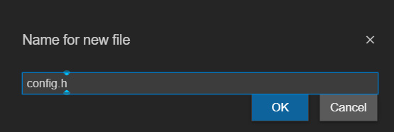
Figure 13.15 – Naming the file
Now, there is a tab called config.h and when you click it, you can paste in the code from the config.h file we looked at earlier. If you copied it from the file that you made previously, your details may already be stored in it – however, if you copied it from the online version, you’ll need to enter in your credentials again.
- In the code, you need to define your username and IO key details, as well as your Wi-Fi ID and Wi-Fi password details. Fill in the information for the following:
#define IO_USERNAME "change"
#define IO_KEY "change"
#define WIFI_SSID "change"
#define WIFI_PASS "change"
That’s all we’ll have to do with this file. Now, we need to modify the main code file that we completed in the previous activity, Activity 13.5 – Using EEPROM.h for memory access.
- Check you are in the correct tab for the main program file (not the config.h file). To start, include the file we just created and added in a tab:
#include "config.h"
This should be added with the other include files at the top of the code. We then need to set up the feed that we created on the io site.
- We set up the feed by declaring it before setup():
AdafruitIO_Feed *scannedTags = io.feed("tags");
Make sure this matches with what you have called your feed if it is different from mine.
- In setup(), we want to connect to the Adafruit io service, so I’m going to add this after I’ve initialized the Serial Monitor. I’m also adding a message to print to the serial monitor so I know that it is connecting:
Serial.print("Connecting to Adafruit IO");
io.connect();
I’ll wait for everything else to initialize and for the lights to come on so the wearer knows something is happening. Then, we wait for a connection to io:
while(io.status() < AIO_CONNECTED) {
Serial.print(".");
delay(500);
}
Serial.println();
Serial.println(io.statusText());
Once it has made a connection, we want the status of our connection printed to the serial monitor. Printing it to the serial monitor when we are writing code and checking it is a great way to see what is going on in our program. I use it a lot as I’m writing code.
- Lastly, we add the code to keep the connection open – this goes at the top of the loop() function and should look as follows:
void loop() {
io.run();
while (getID()) {
- Now that we have all the groundwork done for the connection, we want the tag to be saved and uploaded to the io service every time we scan it. So, we will add the code:
scannedTags ->save(redTag);
This code will go after the memory save has been done and you’ll add one of these for each tag. The completed tagActions() code will now look as follows:
void tagActions(char tag) {
switch (tag) {
case ('0'):
Serial.println("red tag");
redTag ^= true;
EEPROM.write(0, redTag);
EEPROM.commit();
scannedTags->save(redTag);
break;
Now that we have modified the code, we will create a new Dashboard. We’ve created a Dashboard before and it is the same process. Click on the Dashboard link in the top navigation area, and then click the New Dashboard button. This opens a window where you will type in the name of your Dashboard. I’m calling mine Message Bag (see Figure 13.16). Once you’ve typed in the name, click Create:
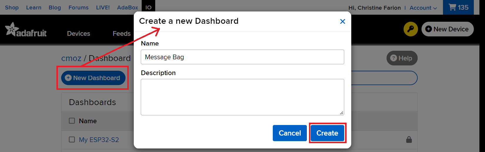
Figure 13.16 – Creating a new Dashboard
After your Message Bag Dashboard is made, we go to Create New Block – click on the settings icon on the right-hand side and choose Create New Block, which opens the window with all the blocks for the dashboard. We want an indicator so we can see whether the tag is scanned or not scanned. Choose the Indicator block (see Figure 13.17):
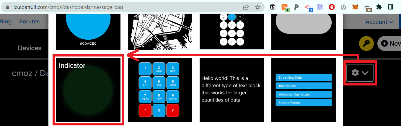
Figure 13.17 – Click the settings symbol on the right-hand side and choosing the Indicator block
There are options we can configure for this block. First, you will need to choose the feed, so check the tags checkbox, and then click Next step (see Figure 13.18):
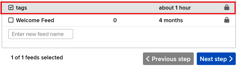
Figure 13.18 – Selecting your feed
Then, you can alter the settings. See the image in Figure 13.19, which shows how you can edit it, including changing the condition. We want it to display the following:
- One color when the value is equal to one, meaning the tag is scanned or the value is true.
- Display a different color when the value is zero, meaning no tag scanned and the value is false.
You can edit these settings and try out sample data to see the change:

Figure 13.19 – Settings for the Status Indicator Block
I’ve chosen red as the primary color and white as the off color. Once you have finished modifying, I have altered the speed of the serial monitor because this board can handle a fast connection and it’s typical for the ESP32 to use a 115200 baud rate. When you open the serial monitor, don’t forget to alter the baud rate there too.
Now, upload your code. The complete code is here if you want to check it against yours: https://github.com/cmoz/Ultimate/tree/main/C13/Activity13_6_IoT. When you scan a tag, watch what happens on your Message Bag Dashboard.
What are your observations?
You’ll notice it kind of works. It does what we asked it to – when there is a tag present, it is one for true and the Status Indicator changes, but it changes our one indicator for all the tags, so it is getting confused. This could be implemented in a better way – we want to know which tag is scanned.
How would you implement it? Think about the problem and when you think you’ve got a solution, jump to the next activity!
Activity 13.7 – Iterations to the IoT connection
After looking at the behavior of the tags when scanned, I want to have one status indicator for each tag that I have. We need to add more feeds for this information. Click on your Feed tab back in io.adafruit.com, and let’s add a feed for each tag (see Figure 13.20):

Figure 13.20 – The feeds for all the tags
I added my feeds to a group called Message Bag to organize them, so my key for these has changed slightly. Instead of referring to them as blueTag, it would be messagebag.bluetag.
Let’s edit our Dashboard now.
Open the Settings tab and choose Create New Block on the Message Bag Dashboard. I’ll create a Status Indicator for each tag. This time, I’m also going to name the Status Indicator to whatever the red tag will represent. For example, I’ll have the red tag in my wallet – so I’ll call it wallet packed. I’ll do this for all five items. I’ll change the scanned color to match the color of the NeoPixel and I’ll choose white for the color when the item isn’t scanned in.
After you have finished creating and you’ve saved your dashboard, we need to modify the code.
At the very start of our code, we have a declaration for the feed we are using:
AdafruitIO_Feed *scannedTags = io.feed("tags");We need to modify this and add the other tags too for the new feeds we’ve created. My code looks as follows:
AdafruitIO_Feed *scannedRedTag = io.feed("messagebag.redtag");
AdafruitIO_Feed *scannedBlueTag = io.feed("messagebag.bluetag");
AdafruitIO_Feed *scannedGreenTag = io.feed("messagebag.greentag");
AdafruitIO_Feed *scannedYellowTag = io.feed("messagebag.yellowtag");
AdafruitIO_Feed *scannedPurpleTag = io.feed("messagebag.purpletag");
The portions that have messagebag in them are there because I put them in a MessageBag group. Delete that part of the tag identifier if you didn’t make a group.
We also need to update where we are sending the tag state, which is reflected in this line:
scannedTags->save(redTag);
This will need to be amended to the following:
scannedRedTag->save(redTag);
Change all the code instances where this code appears in the tagActions() function. After you have finished, upload the code and try out your Message Bag Dashboard now. My completed code for this activity is here for you to check your code against: https://github.com/cmoz/Ultimate/tree/main/C13/Activity13_7_IoTImproved. Figure 13.21 shows three views of my dashboard, with the first showing all tags are not scanned. The middle view shows that some of the tags have been scanned – the red, blue, and yellow and the objects they represent – and lastly, all tags are scanned in the final part of the diagram:
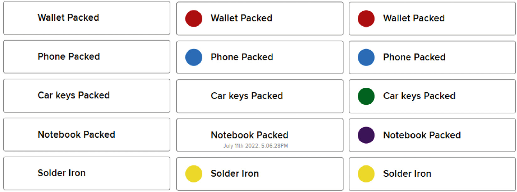
Figure 13.21 – Message Bag Dashboard online reflecting the scanning of tags in real time
Hopefully, you’ll notice that it’s surprisingly fast! We can see the changes in real time, with a slight delay but it’s very accurate. If you make the Dashboard public and send yourself the link, you’ll be able to see the tag scanning on your phone (see Figure 13.22):

Figure 13.22 – The IoT service on my mobile phone as I scan tags
I hope you’ve enjoyed adding IoT capabilities to this circuit. You might look at adding other functionality too. You could connect a screen or other peripherals through the STEMMA connection. The STEMMA I2C connection is broken out and separated from the pins on the board so you can chain other devices. A screen could display the Wi-Fi connection information or similar. There is also a sewable Flora GPS component that you could add. You could perhaps track where the items were scanned and this location could be displayed on an IoT service privately. How about sound or vibration as another confirmation for the wearer? Adding other ways that wearers can interact with your system, or including ways to make it more accessible, should always be a goal or part of the subtext in a system we design for people. Additionally, although our circuit board is tiny, there are smaller RFID readers that you can try too.
Always remember to think about the purpose, use, and how it affects someone’s goals before adding it. Let’s finish up by adding a reminder to use what we make as the first round of important testing for our wearables.
Use it or do something else
This concept is one that is so important when designing with people for people. When we create our prototypes, it’s essential that we take the important step of trying them ourselves. It doesn’t matter if it is larger than what you’d like or if your soldering is wonky – it’s about using it to discover how we can make it more seamless with our goals.
Activity 13.8 – The importance of using your wearable and observing what’s around you
When you’ve completed a prototype, regardless of the implementation, test it. Wear it. Bring it with you. Everywhere.
Now that we’ve created Message Bag, we should be using it over the course of several days in the first instance. Bring a notebook with you and write down observations of it in use. I’ve done this for extended periods of time and used a similar version in many situations. Try to use your device in the shops, when traveling, visiting friends, and at work. Take it with you in as many situations as you can to test the use. One example of valuable feedback was when I’d made a version with a tone that confirmed every scan. I quickly realized it was too loud or that it should have a volume control when I visited a quiet café!
This activity is about making notes and drawings to document how you can make your wearable more suited for your purpose. After you’ve made your observations over many days, iterate the prototype. Then, repeat this cycle. You should use what you make if you want others to use it.
Summary
This chapter focused on iterations of Message Bag, alongside putting into practice several of the skills that we’ve been working on throughout the book. We looked at a template for designs, how to start our projects, and whether we want to focus primarily on the technology we have to skill up or whether we want to focus on a certain context. We discussed our observations when using the proof-of-concept prototype that we created on a breadboard and the ways that this could be improved. This gave us the content to make iterations and finish off the wearable design to create an integration prototype. We soldered and sewed it into place too, completing the project nicely.
After completing Message Bag, we learned that all prototypes have opportunities for improvement. Often, we can swap out a component for a smaller one, or something with more functionality. In this chapter, we looked at adding memory, used to store our tag scanning, and adding IoT capabilities so we could even see on our phones what tag we had scanned. We finished with a reminder to always use what we make so we can improve our wearables and make them more suited for our purpose.
I’m sad to say that the next chapter is the last chapter, but we have some exciting concepts to look forward to. We take a sneak peek at what the future of wearables might look like. We’ll learn some top tips and tricks for creating durable and interesting wearables, as well as pushing your prototyping further using new and unusual techniques!
References
As a final note, I wanted to highlight some research and projects where RFID technology has been used. This could provide a springboard for your own wearables and possible applications for this type of interesting and useful technology. These research papers are a good start with differing applications for RFID technologies:
Sedighi, P., Norouzi, M. H., & Delrobaei, M. (2021). An RFID-Based Assistive Glove to Help the Visually Impaired. IEEE Transactions on Instrumentation and Measurement, 70, 1-9. https://wp.kntu.ac.ir/delrobaei/files/TIM_2021_Delrobaei.pdf.
Dang, Q. H., Chen, S. J., Ranasinghe, D. C., & Fumeaux, C. (2020). Modular integration of a passive RFID sensor with wearable textile antennas for patient monitoring. IEEE Transactions on Components, Packaging and Manufacturing Technology, 10(12), 1979-1988. https://ieeexplore.ieee.org/abstract/document/9249015.
Zhong, T., Jin, N., Yuan, W., Zhou, C., Gu, W., & Cui, Z. (2019). Printable stretchable silver ink and application to printed RFID tags for wearable electronics. Materials, 12(18), 3036. https://www.mdpi.com/1996-1944/12/18/3036.
Wang, C., Liu, J., Chen, Y., Xie, L., Liu, H. B., & Lu, S. (2018). RF-kinect: A wearable RFID-based approach towards 3D body movement tracking. Proceedings of the ACM on Interactive, Mobile, Wearable and Ubiquitous Technologies, 2(1), 1-28. https://dl.acm.org/doi/abs/10.1145/3191773.
Jiang, Y., Xu, L., Pan, K., Leng, T., Li, Y., Danoon, L., & Hu, Z. (2019). e‐Textile embroidered wearable near-field communication RFID antennas. IET Microwaves, Antennas & Propagation, 13(1), 99-104. https://ietresearch.onlinelibrary.wiley.com/doi/full/10.1049/iet-map.2018.5435.
Tajin, M. A. S., Amanatides, C. E., Dion, G., & Dandekar, K. R. (2021). Passive UHF RFID-based knitted wearable compression sensor. IEEE internet of things journal, 8(17), 13763-13773. https://ieeexplore.ieee.org/abstract/document/9383785.
Chen, Y. L., Liu, D., Wang, S., Li, Y. F., & Zhang, X. S. (2019). Self-powered smart active RFID tag integrated with wearable hybrid nanogenerator. Nano Energy, 64, 103911. https://www.sciencedirect.com/science/article/abs/pii/S2211285519306184.
Luo, C., Gil, I., & Fernández-García, R. (2020). Wearable textile UHF-RFID sensors: A systematic review. Materials, 13(15), 3292. https://www.mdpi.com/1996-1944/13/15/3292.
Review questions
- What does setting our road map involve? How might you plan your wearable project?
- Why is it important to iterate our designs?
- What is non-volatile memory?
- Describe positive feedback and give one example of it.
- What is EEPROM?
- What do we always need to be aware of when using flash memory?
- What is a global object or global variable?
- What is an integration prototype?
- Why do we tin our wire?