9
Creating a Realistic Flag
There are many tutorials out there for creating flags using the cloth simulation. However, that raises the question, what makes this tutorial unique and different?
Well, let me tell you! If you look at real flagpoles, there are many different parts to them. For example, the hoist is the part of the flag that attaches to the halyard. The halyard is the rope that raises and lowers the flag from the ground. There are also snap hooks that attach the flag to the halyard. In this step-by-step tutorial, we will be adding all those different parts to our flag to create the most realistic result!
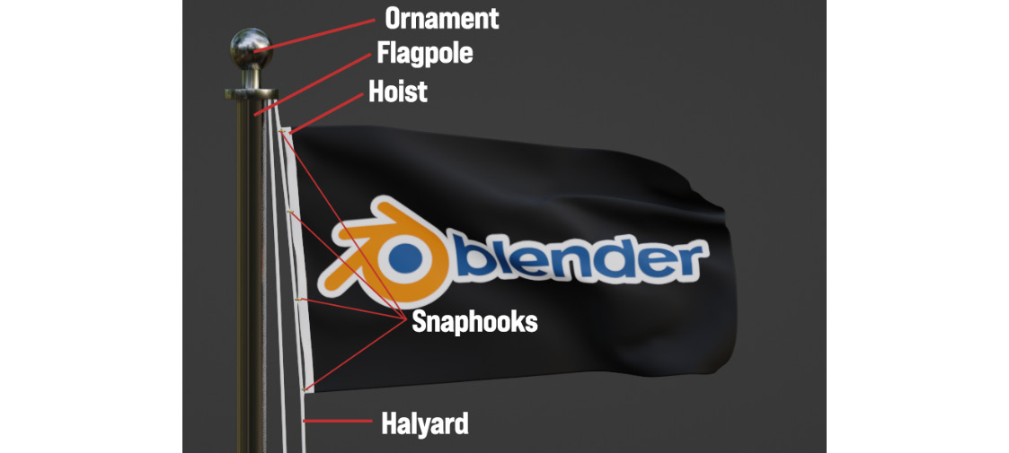
Figure 9.1 – A flag diagram
We will start by adding all the objects we need for the scene, such as the flag, the flagpole, the rope, and the hooks. Then, we will move on to creating the simulation and attaching the flag to the rope. Finally, we will create the materials and render them out.
Here are the topics we will cover in the chapter:
- Adding the objects
- Creating the simulation
- Making the materials
- Rendering the animation
Technical requirements
This chapter requires you to have Blender version 3.0 or above installed.
To download Blender, visit www.blender.org.
There is also a texture that we will be using later in this chapter. To get the texture, visit https://github.com/PacktPublishing/Learn-Blender-Simulations-the-Right-Way/tree/main/Chapter09.
Adding the objects
The first thing we need to decide is how big we want the flag to be. The size of the flag also depends on the height of the flagpole. For example, a pole that is 6 meters or 20 feet would have a flag that is about 91 x 152 centimeters or 3 x 5 feet. The taller the flagpole, the bigger the flag should be. With that in mind, let’s go ahead and get started with this tutorial.
Creating the flag
For this tutorial, we are going to be creating a flag that is 91 cm x 152 cm. So, to create it, follow these steps:
- Open a new scene in Blender. You can also go ahead and delete the default cube; we won’t need that for this scene.
- Press Shift + A and add in a plane object. Next, set the dimensions by opening the Properties panel by pressing N and then setting Dimensions to 1.52 m for the X axis and 0.91 m for the Y axis.

Figure 9.2 – Flag dimensions
- Let’s also rotate this plane by 90 degrees so that it’s standing upright. And make sure to apply the scale and rotation by pressing Ctrl/Cmd + A to select both Scale and Rotation. This way, all the values are correct, and the simulation will work properly!
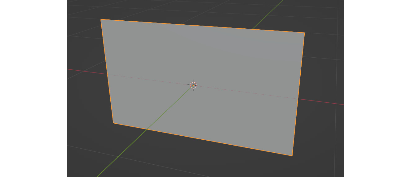
Figure 9.3 – Flag example
- The next step is to add more geometry to our plane. Since our plane is a rectangle, if we subdivide the whole thing, we will also get rectangle faces. However, we want square faces instead. To get square faces, you need to manually add two vertical loop cuts and one horizontal one. You can do this by going into Edit Mode, pressing Ctrl/Cmd + R, and hovering your mouse over one side of the plane. Then, use the scroll wheel to add multiple loop cuts.
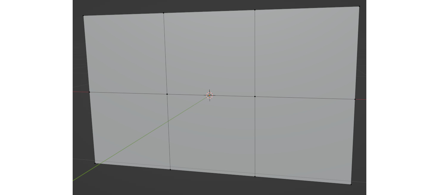
Figure 9.4 – Loop cuts
- Now, we can subdivide the whole thing, and we will get square faces. Press A to select everything, right-click, and select Subdivide. Then, open the panel at the bottom and set Number of Cuts to 15.
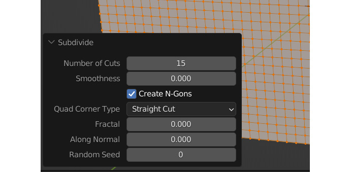
Figure 9.5 – Number of Cuts
And that is it for the flag! Next up, let’s create the flagpole!
Creating the flagpole
At this point, it’s a good idea to look at some reference images of real-life flagpoles so that you can get an idea of what yours should look like. The main part of the flagpole is the cylindrical shape, and normally at the very top sits a brass or silver ball. One of the main purposes of the ball at the top is to give the flagpole a more aesthetically pleasing design, and it prevents the flag from sliding off the top of the pole.
With that in mind, let’s start modeling:
- To start, press Shift + A, go to Mesh, and add a Cylinder object to the scene. Open the Add Cylinder menu at the bottom left of the viewport, and let’s change a couple of settings. The radius of the cylinder should be around 0.05 m and the Depth (which is the height) should be set to 6 m.

Figure 9.6 – Flagpole dimensions
- Next, we are going to extrude and scale the top face to add a bit more interest to the look of the flagpole. Select the top face and press E to extrude, and then you can press S to scale out that face. Keep extruding and scaling until you get something that looks like the following figure!
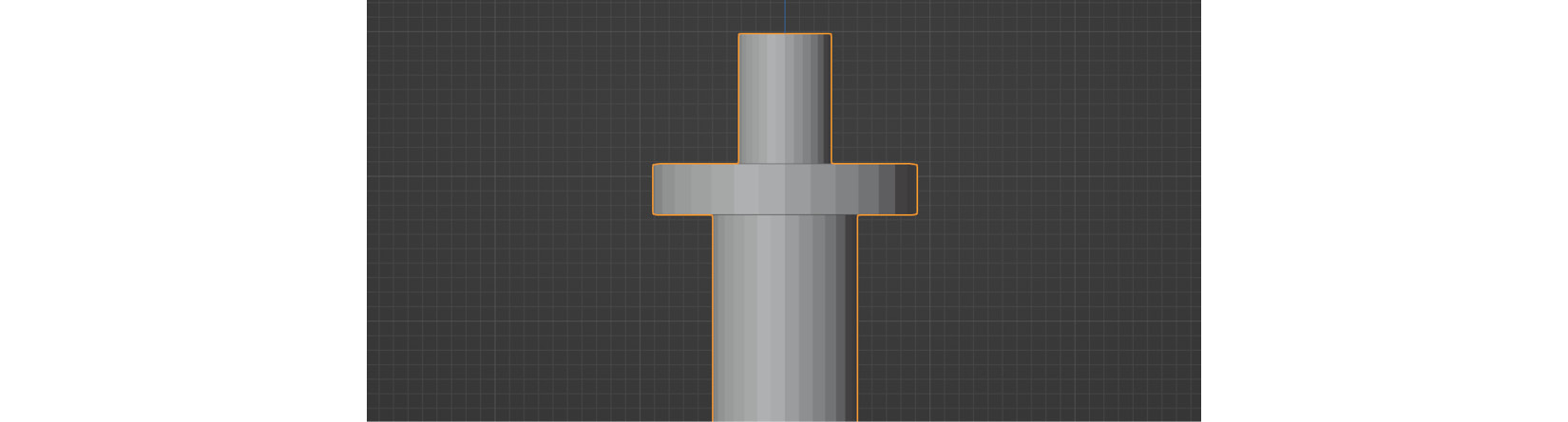
Figure 9.7 – Extruded face
- Let’s also add a UV sphere to the top of the flagpole. This is going to represent the ornament that sits at the very top!

Figure 9.8 – UV sphere added
- To round the edges of the pole so that they don’t look as sharp, you can add a Bevel modifier. Looking at the Bevel settings, Amount controls how round the edges will be; let’s set this value to something very low, such as 0.002 m. Then, set the Segments option to 3.
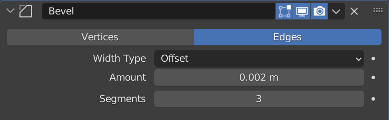
Figure 9.9 – The Bevel modifier
- And, of course, right-click and select Shade Smooth for both objects to make sure everything looks good. Here is what the pole should look like so far:

Figure 9.10 – The finished flagpole

Figure 9.11 – The flag position
Great! Now, we can work on creating the rope to hold the flag to the pole!
Creating the rope
The next thing that we will be creating is the rope that attaches the flag to the pole:
- Add in a new Cylinder object. Then, set its vertices to 4, the radius to 0.008 m, and the depth to 6 m to match the height of the flagpole.

Figure 9.12 – Rope values
- This rope object is also going to have the cloth simulation applied to it. This way, it will swing and move around with the flag. For this to work, we need more geometry, so let’s go into Edit Mode and add some loop cuts.
Press Ctrl/Cmd + R and then type 200 to add 200 horizontal loop cuts.
- Normally, the rope goes through a pully system. This allows the flag to be raised and lowered. To simulate this, let’s duplicate the rope so that now there are two ropes.
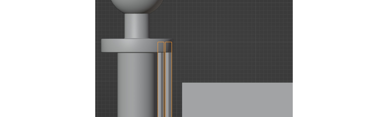
Figure 9.13 – Rope position
Place the ropes in between the pole and the flag, as you can see in Figure 9.13, and then we can move on to creating the hooks!
Creating the hooks
With real-life flags, depending on the size, there are usually two to four hooks that attach the flag to the rope. For this tutorial, we will be adding four hooks:
- Press Shift + A and add a Torus object.
- Scale it down and place it at the top-left corner of the flag.
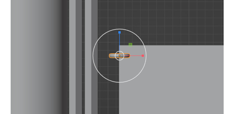
Figure 9.14 – The hook position
- Now, we need to make sure this object moves with the flag as it’s simulating. To do this, we are going to parent the torus to the top-corner vertex of the flag. So, go into Edit Mode with both objects selected.
- Now, select the entire torus first, and then hold Shift and select the top-corner vertex.
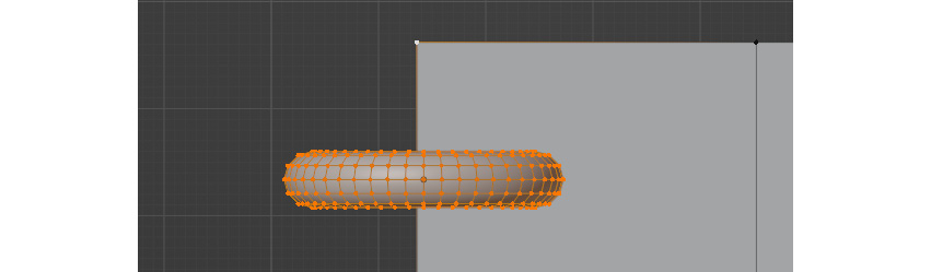
Figure 9.15 – Vertex selection
- Press Ctrl/Cmd + P and select Make Vertex Parent. Now, the torus will be parented to that vertex, and wherever it goes, the torus will follow!
- Repeat steps 1 through 5 for the remaining hooks you want to add!

Figure 9.16 – Rings added
After you have added the rest, we can move on to the cloth simulation!
Creating the simulation
Now that all the objects in the scene are here, we can create the simulation. But before we do that though, there are a couple of things to do first:
- Select the rope and the flag. Then, press Ctrl/Cmd + J or go to Object | Join; this will join those two objects together as one so that our simulation will work properly.
- Next, let’s add a Wind force field to the scene. To do this, press Shift + A | Force Field | Wind.
- Head over to the Physics panel and set Strength to 5000. We need quite a high strength for the cloth to move around. Next, set Flow to 0 and Noise Amount to 5, which will give us more variation in the wind!
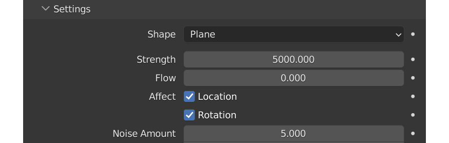
Figure 9.17 – Wind wettings
- Place the wind force field on the left side of the flag.
Now, let’s create the cloth simulation!
- Select your flag and head over to the Physics panel.
- Now, select Cloth. We are going to start at the top and work our way down the settings, changing them as needed. The first thing we’ll change is Quality. This will increase the accuracy of the simulation and help prevent any errors. Since the ropes and the flag will be interacting with each other, we need to set Quality to a high value so that we get a nice simulation. Let’s go with a value of 30.
- Our cloth currently weighs way too much, and the wind is hardly going to affect it. To fix this, let’s set Vertex Mass to 0.03.
- Since the wind strength is so high, let’s set Tension in the Stiffness tab to 25 to make sure that the cloth doesn’t stretch.
- As for Bending in the Stiffness tab, set this value to 0.4 so that we get slightly smaller wrinkles and bends.
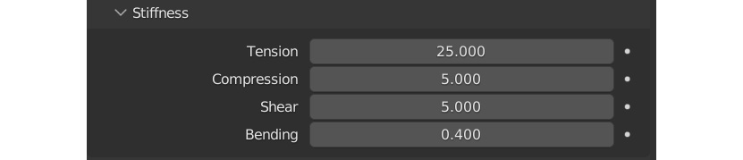
Figure 9.18 – Stiffness values
Now, let’s create the pin group so that the flag stays in place and doesn’t just fall straight down. For this, we need to create a vertex group and assign some of the vertices to it.
- Head over to the Object Data panel and create a new vertex group by hitting + on the right side.
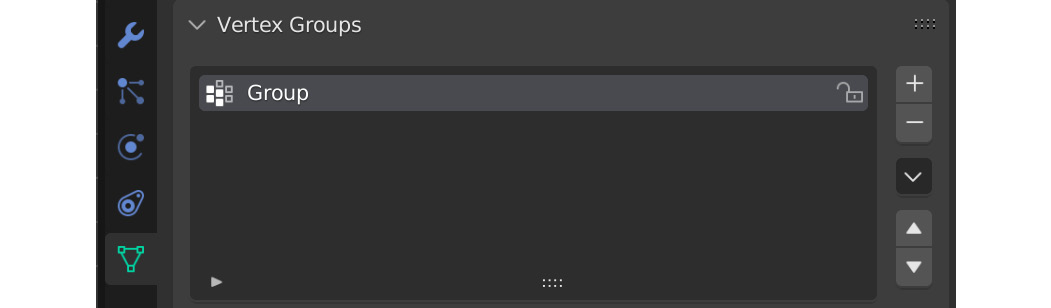
Figure 9.19 – Vertex Groups
- Now, go into Edit Mode with the flag selected and assign the top row of faces of the ropes to that vertex group. View the following figure to see which row of faces to select!
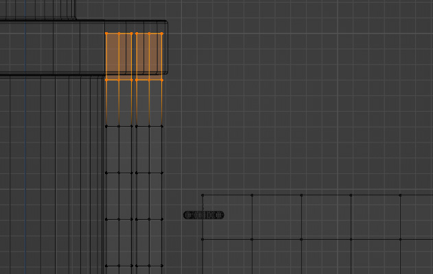
Figure 9.20 – Top faces on the rope
- Select the bottom row of faces of the rope and assign those vertices as well.
- The other thing we are going to be doing is tightening up this rope. If we play the simulation right now, the rope is going to arch far away from the flagpole because the wind is pushing it. We want it to be a little tighter and closer to the flagpole.
We will be using the Sewing feature in the cloth simulation to achieve this:
- First, delete six rows of faces at the bottom of the rope.
- Next, we need to fill in those faces. Select the parts of the mesh that need to be filled and then press F to create a face.
- Finally, we need to create an edge to connect the parts of the rope. Select a vertex on each side and press F again to create an edge. View the following figure to see the progression.
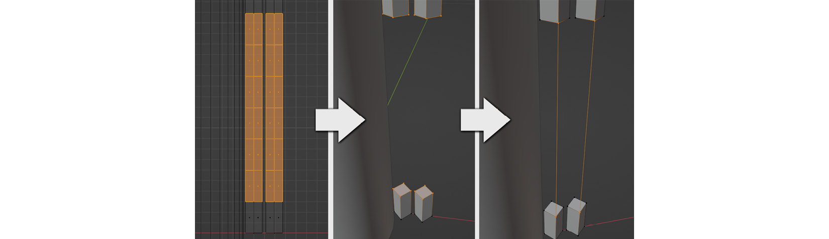
Figure 9.21 – A rope tightening example
Now, when we enable the sewing, that edge is going to be pulled together and the rope will be tightened!
- The Sewing feature is also how we will be hooking the flag to the rope! Find the vertices you want to attach between the rope and the flag, and press F to fill in an edge:
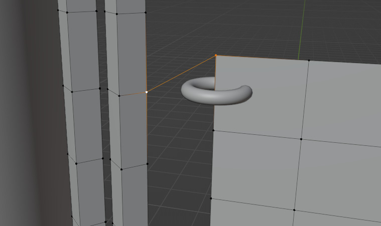
Figure 9.22 – The flag attachment
Do the same thing for the remaining hooks on the flag. Don’t worry if the edge is not straight; this will actually give the flag some randomness and make it look better!
- Back over in the cloth simulation settings, jump down to the Shape tab, select that vertex group for the pin group, and enable Sewing. Then, look at Max Sewing Force, which sets how strong those edges will be pulled together; we’ll set it to 15!
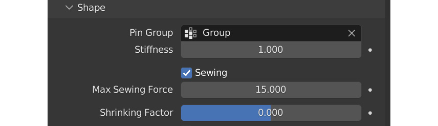
Figure 9.23 – Shape settings
Now, when we play the simulation, the rope should tighten, and the flag should be hooked to the rope at the top!
- Finally, the last step before we bake the simulation – let’s set up the collisions! Open the Collision tab and set Quality to 4. This will give us more accurate results. Turn on Self Collision and lower the distance to 0.005.
- With that done, we can bake in the simulation! Head up to the Cache tab and set End Frame to 200 or however long you want your animation to be, and then click Bake!
All the settings we just talked about are just a baseline to create a nice-looking flag. Feel free to change and customize anything to your liking. For now, we are ready to move on to creating the materials!
Making the materials
For this next section, we will be creating all the materials for our scene! Starting out with the flag, we will be learning how to UV unwrap an object and assign a texture to it. After that, we will also create the materials for both the flagpole and the hooks! Let’s get started!
Creating the flag material
Follow these steps to create the flag material:
- The first thing we need to do is decide what texture we will be using for our flag. You could use your country’s flag or the Blender flag that I have created for this chapter. Here is the link to download that texture: https://github.com/PacktPublishing/Learn-Blender-Simulations-the-Right-Way/tree/main/Chapter09.
- Once you have a texture ready to go, add it to the material. To do so, head over to the Material panel and create a new one.
- Next, click on that yellow dot next to the base color of the Principled BSDF shader, choose Image Texture, and open the flag texture you have downloaded.
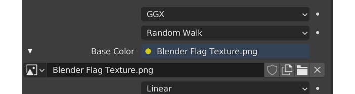
Figure 9.24 – The flag texture
- Now that the texture is added, we need to UV unwrap our flag so that the texture can be applied correctly. Skip to Frame 1 and go into Edit Mode on the flag. Select the entire flag, press U, and select Unwrap.
- If you press Z and go into Material Preview, you might notice that the texture is not in the correct spot. To fix it, let’s split the window and open the UV/Image Editor. You can do this by moving your mouse to the right side of the viewport until it turns into a double arrow.
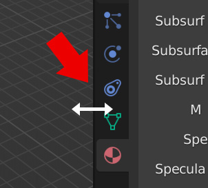
Figure 9.25 – Double arrow
Then, right-click, select Vertical Split, and place that split in the middle of the screen.
- Then, go up to the top-left corner and switch Editor Type to UV Image Editor. Now, you should see the UV map and how it’s rotated the wrong way.
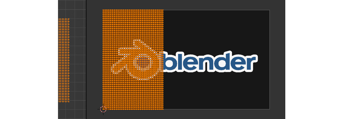
Figure 9.26 – The UV map rotated
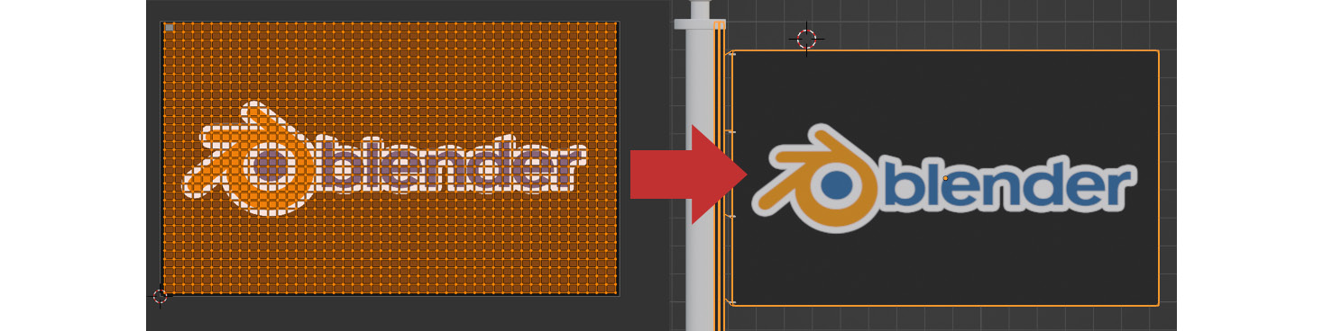
Figure 9.27 – The UV corrected
- Back in the Principled Shader, let’s set Roughness to 0.9 so that it’s not as glossy!
- The other thing that we need to do is create a new material for the rope. Right now, since the rope and flag are one object, they are sharing the same material. To fix this, hit the + button on the right side to add a slot material. Then, click New.
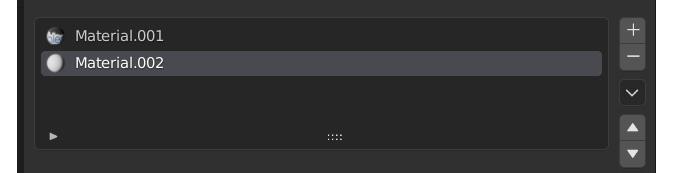
Figure 9.28 – A slot material
- We can leave this new material with the default Principled BSDF shader. We don’t need to change anything else. Then, all you have to do is go into Edit Mode, select the rope, and click Assign with that new material selected.
- At the beginning of the chapter, we talked about the hoist of the flag, which is the part that attaches to the rope. To create this, select the column of faces on the left side of the flag. Then, assign that same white material to those faces. You can see an example of this in the following figure:
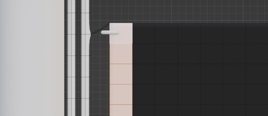
Figure 9.29 – Creating the hoist
With that done, let’s work on the hooks and create a nice gold metallic material!
Creating the hook material
The hooks for flags are usually a silver or gold color, which are pretty simple to do:
- Select one of the hooks and click New to create a new material.
- Set Metallic to 1 and Roughness to 0.1. This will give the material a nice glossy look.
- Then, set Base Color to an orange-yellow color, which will give it a gold look.
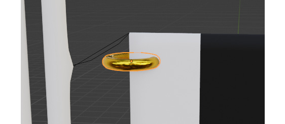
Figure 9.30 – A gold material
And that material is done! Then, just assign the rest of the hooks to share that material and we can move on!
Creating the flagpole material
The flagpole material is also going to be a nice metallic material, except this time, we are going to give it a silver look:
- Select the flagpole and create a new material.
- Set Metallic to 1 and Roughness to 0.2.
- As for Base Color, let’s set this to a light gray color.
And there is it! All the materials are done, and now we can move on to the final touchups before we render the animation!
Rendering the animation
Our scene is coming along great, but for this last section of the chapter, we will be going over some final tweaks and touchups to make our render look good:
- Let’s start by working on the flag. To smooth out the wrinkles and give it an overall better look, let’s add a Subdivision Surface modifier. Head over to the Modifier panel, click Add Modifier, and select Subdivision Surface. Set both the Viewport and Render levels to 2.
- Right now, our flag is completely thin, which isn’t very realistic, so let’s add a Solidify modifier to give it just a little bit of thickness. Set Thickness to something much lower, such as 0.002.
- As for the lighting, I recommend using an HDR (High Dynamic Range) for the most realistic results. You can get very high-quality HDRs for free at polyhaven.com. Once you have found an HDR that you like, head over to the World panel, click the yellow dot next to Color, select Environment Texture, and open the HDR in the scene!
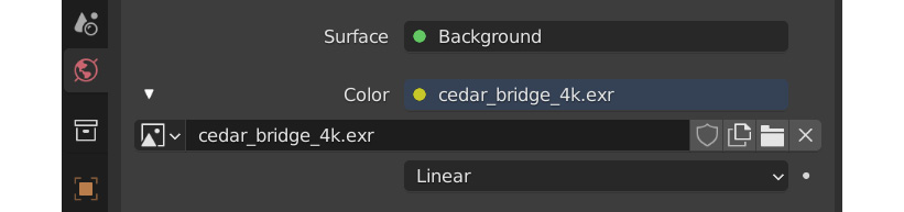
Figure 9.31 – HDR
- Next, head over to the Eevee settings and turn on Ambient Occlusion to add shadows to the corners, and turn on Screen Space Reflections to add nice reflections to the materials.
- In Color Management, set Look to High Contrast to make the colors pop a bit more.
- After that, you can set up the camera to wherever you like. A good position would be looking up at the flag. This would give a nice perspective and height to the flagpole.
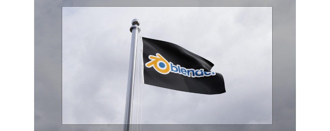
Figure 9.32 – The camera position
- Finally, the last step is to set the end frame in the timeline to match the length of your simulation.
At this point, we are ready to render. Make sure to set your output and the file type that you want. From there, head up to Render and select Render Animation!
Summary
We have now created a nice realistic flag using the cloth simulation in Blender! Hopefully, you learned a thing or two and created something cool in the process! And, as always, let’s recap what we covered in this chapter.
First, we discussed the different things that make up a flag and the sizes and heights. After that, we added and modeled all the objects we needed. We created the simulation and used the Sewing feature in the cloth simulation to tighten and attach the flag to the rope. We also created the materials and learned how to add the texture to the flag. And finally, we did some final touchups and rendered the animation!
It’s always good to practice as well following a tutorial! This way, the steps and things you learned really sink in! I encourage you to create another project using the cloth simulation – maybe a huge medieval banner or a cape flowing in the wind from a character!
Not only is this the end of the chapter but also the end of Part 2 of this book! In the next couple of chapters, we will be diving deep into the rigid body simulation and learning all about what it is and how it works in Blender!