11
Creating a Rigid Body Physics Course
Now that we have a good understanding of how the rigid body simulation works in Blender, let’s take everything we learned in the last chapter and apply it to a real project!
In this chapter, we will be learning how to use the rigid body simulation to create a full physics-based animation.
We will start by learning how to create a wrecking ball and a domino effect. Then, we will move on to animating materials, creating an elevator using constraints, using animated rigid bodies, adding hinge constraints, and finally, we will be destroying a tower of cubes to finish off the animation.
The goal of this chapter is to understand how to use the rigid body simulation in a practical way to create a nice satisfying animation! Here are the topics we will cover:
- Creating the simulation
- Adding the camera animation
- Setting up the render
Technical requirements
This chapter requires you to have Blender version 3.0 or above installed.
To download Blender, visit www.blender.org.
Also make sure to download the setup file for this tutorial here: https://github.com/PacktPublishing/Learn-Blender-Simulations-the-Right-Way/tree/main/Chapter11.
Creating the simulation
Before we get started, make sure to download the Rigid Body Course Setup.blend file. This will include a basic scene, with some models and materials already in place and HDR for lighting. Each object is named accordingly, so it’s easy to navigate.
Once you are familiar with the scene, we can go ahead and start creating the simulation. If you would like to download the finished scene, Rigid Body Project File.blend, for reference, you can do that as well!
Working with Complex Rigid Bodies
When working with complex rigid body simulations, Blender tends to crash and be unresponsive. Remember to constantly save your Blender file throughout this tutorial so that you don’t lose progress if and when the program crashes.
Creating the wrecking ball
Let’s get started by simulating the wrecking ball crashing into one of the blue cubes! To do this, we’ll use the rigid body Object menu to add physics to all the chains at once:
- Select all the objects and head up to Object | Rigid Body | Add Active.
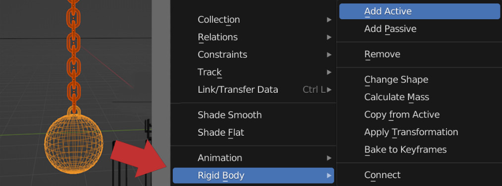
Figure 11.1 – Wrecking ball physics
- There are a couple of settings we need to change for these chains. With all of them still selected, head over to the Physics panel:
- Set Mass to 4 kg. This will prevent the chains from breaking from the weight.
- Next, let’s change the shape of the collision. Because these chains are interlocking, Convex Hull will not work. Instead, we need to use Mesh; this way, the collision works properly, and the chains don’t break.
- And finally, let’s set Margin in Sensitivity to 0 m. This will make sure the chains touch each other and don’t jitter around!
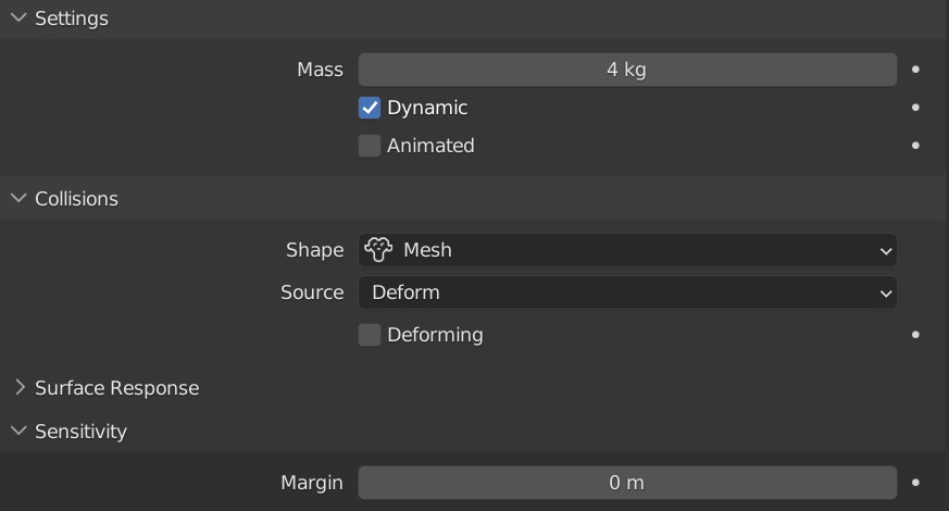
Figure 11.2 – Wrecking ball settings
- Now, let’s copy those changes to the rest of the chains. You can do this by making sure that they are all still selected and the one with those changes is the active object, and then head to Object | Rigid Body | Copy From Active.
- Select the wrecking ball object. In real life, this would weigh a lot more, so let’s set Mass to 20 kg in the Settings tab. Also, change Damping Translation and Rotation to 0.400 in the Dynamics tab. This will make the wrecking ball stop swinging as the animation plays.
Figure 11.3 – Damping values
- Then, select the Chain Top object and turn off Dynamic. This will make sure it stays floating and doesn’t fall.
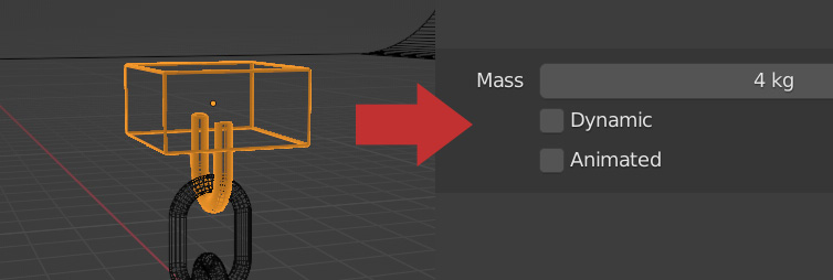
Figure 11.4 – Chain top settings
Normally, the Passive type is used for platforms or bigger surface areas; however, Active with Dynamic turned off is better for more complicated meshes.
From here, you will be able to play the animation and the wrecking ball should swing! Next up, let’s create the domino effect!
Creating the domino effect
Creating this domino effect is actually very easy! All we have to do is select each of the cubes in the circle and click Add Active in the rigid body Object menu.

Figure 11.5 – Selected cubes
We don’t need to change any settings in the Physics panel; the default values will work perfectly fine for these objects. Also, another important step is to select the Floor object and select Add Passive in the rigid body Object menu. This way, the cubes stay where they are and don’t fall through the floor!
Feel free to change the shape of the domino line to how you like. You could have it go all the way around the scene or split off into two directions! Just make sure that it eventually comes around and hits the Button Cube object because this is what triggers the elevator to go up, which we will talk about now!
Before moving on, this is a good time to save the Blender file (you should do this regularly as you move through the chapter).
Simulating the elevator
Next up is the elevator that carries the sphere to the top of the course. To create this, we will be using a motor constraint! Let’s first start by animating the button on the Button Cube object to turn green when the last domino hits it:
- Select the Button Cube object and set it to a Passive rigid body. This way, it will interact with the scene.
- Now, to make it turn green, find the frame when the cube hits the button. You can find the frame by playing the animation from the beginning of the timeline (unfortunately, simply scrubbing through the timeline will not work). For my scene, it was at Frame 120, but yours may be slightly different.
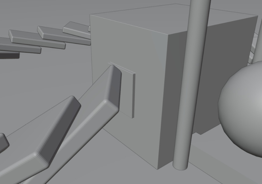
Figure 11.6 – Frame 120
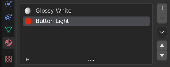
Figure 11.7 – The Material panel
- Let’s go to the previous frame (119) and add a keyframe to the Color value in the Emission shader. You can do this by hovering your mouse over the color and pressing I, or by clicking the little dot next to the color.
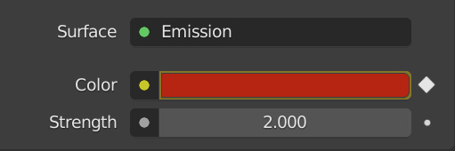
Figure 11.8 – The Emission Color keyframe
- Jump to the next frame (120) and change the color to a nice green, and add another keyframe. Now, when the cube hits the button, it will turn green!
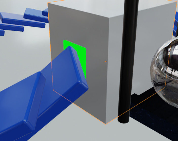
Figure 11.9 – The button turning green
- To create the motor constraint, let’s set the Elevator Platform object to be an Active rigid body, set the collision shape to Mesh, and the Sensitivity margin to 0 m.
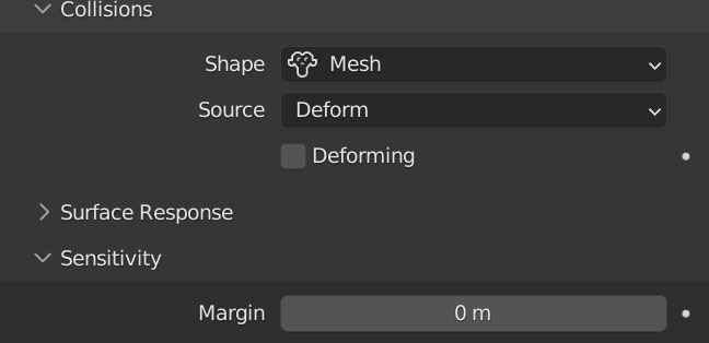
Figure 11.10 – Elevator settings
- With the Elevator Platform object still selected, press N to open the Properties panel. Let’s lock all the Rotation and Location axes except for the Z location; this way, when we add the motor constraint, it will only move up along the Z axis.
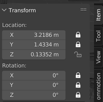
Figure 11.11 – Locked properties
- Select both the Button Cube and Elevator Platform objects and head to Object | Rigid Body | Connect. This will create a constraint between these two objects.
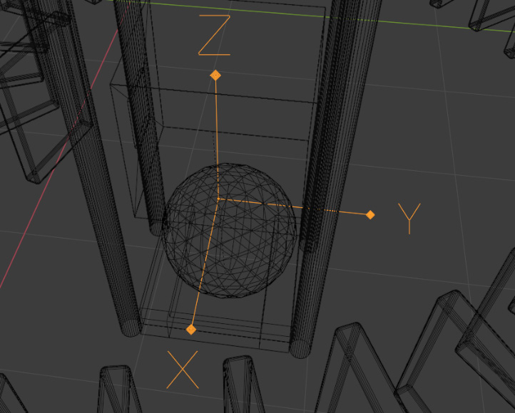
Figure 11.12 – An empty constraint
This constraint will have X, Y, and Z directions. Keep the rotation of these directions in mind when working with constraints!
- Select the Constraint object that has been added and change a couple of settings in the Physics panel:
- Change Type to Motor.
- Enable Linear.
- Set Target Velocity (which controls the speed) to 2 m/s.
- Set Max Impulse (which controls the strength of the motor) to 250, a strong enough value to carry the sphere up.
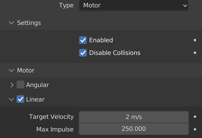
Figure 11.13 – The Motor settings
- When working with motor constraints, the -X direction is the way the motor will go. With this in mind, let’s rotate the motor constraint so that the X direction is pointed downward. This will cause the elevator to move up!
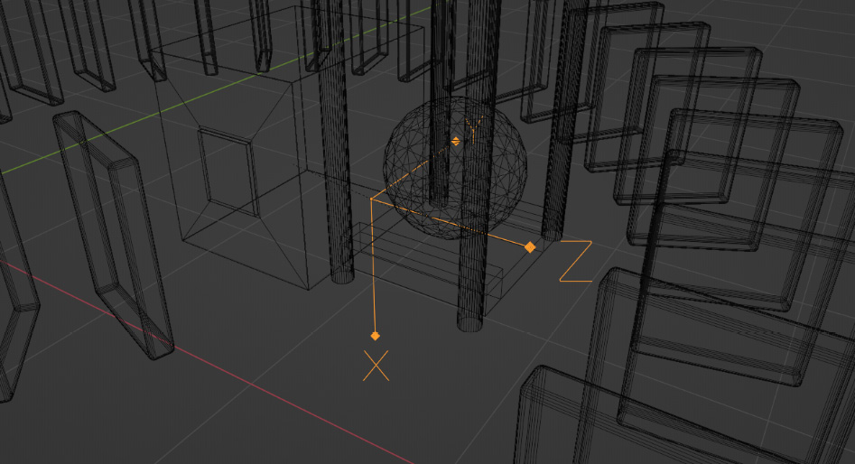
Figure 11.14 – Motor constraint rotation
Make sure to play the animation to see whether everything is working properly and the platform is rising.
- We don’t want the elevator platform to move until the button turns green, so let’s jump to the frame right before the button turns green (119), uncheck Enabled in the Constraints settings, and add a keyframe.
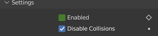
Figure 11.15 – Animating Enabled
On the next frame (120), turn on Enabled and add another keyframe. And there we go – the motor constraint won’t turn on until Frame 120 when the last domino hits the button!
- The other thing we want is for the elevator to stop at a certain point, which we can do by adding a Generic constraint:
- Select Elevator Platform and Button Cube, and connect them again by going to Object | Rigid Body | Connect.
- Select the new constraint object that has been added and change Type to Generic.
- In the Linear tab, turn on Z Axis and set Upper to 6 m. This will cause the elevator to stop when it reaches 6 meters in the air, and this is the exact height we need to reach the platforms at the top!
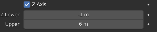
Figure 11.16 – Generic constraint settings
- Finally, select the Sphere, and set it to be an Active rigid body with a mass of 4 kg.
Before you play the animation, make sure to save your Blender file again. After that, play the animation, and make sure that everything works properly and the elevator rises into the air!
Upper and Lower Values
If the elevator stops too early, you may want to change Z Lower to a value of -6 m in the generic constraint settings. This is because the upper and lower values are determined by which object is active when they are connected.

Figure 11.17 – The elevator rising
Next up, we will animate a cube smacking into the sphere and shooting it along the platform!
Animated rigid bodies
When the sphere reaches the top of the elevator, we are going to have a cube slide out and hit it, sending it around the half circle! To do this, follow these instructions:
- Firstly, we need to extend the rigid body simulation because currently it only lasts for 250 frames. So, open the Scene Properties panel, and in Rigid Body World tab underneath Cache, set End to 500.
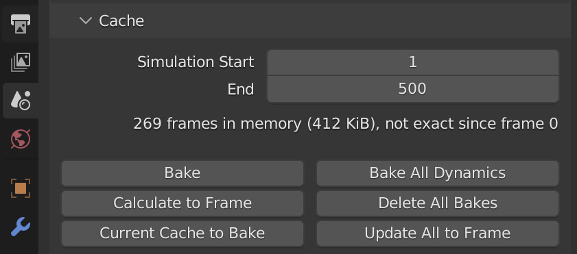
Figure 11.18 – The Cache panel
Now, the simulation will last for 500 frames rather than only 250.
- Now, let’s add physics to the Cube Hit object. Select it and give it an Active rigid body, with the Animated checkbox ticked.
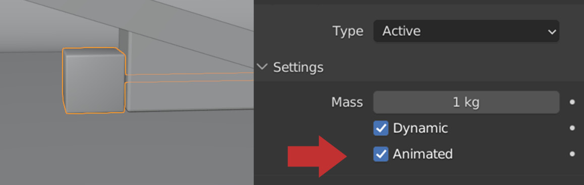
Figure 11.19 – Cube Hit physics
- Play the animation until the elevator reaches the top and stops bouncing. For my scene, it was at Frame 220. If your scene is taking a long time to calculate, you can set the simulation start to the frame right before the motor constraint activates (around 120). This way, you don’t have to wait; just remember to set it back to 1 when you do a final bake!
With the Cube Hit object selected, let’s press I and add a Location keyframe on Frame 230.
- Five frames later, let’s move the Cube Hit object inside the Sphere and add another Location keyframe.
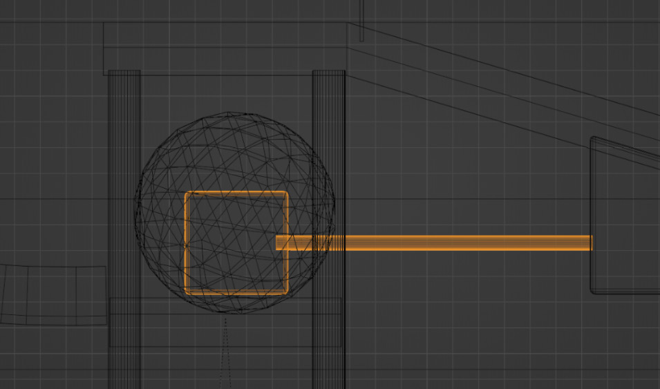
Figure 11.20 – Hitting the sphere
Over the course of five frames, the cube will extend outward and smack the sphere, sending it around the half circle.
- Now, let’s add physics to the rest of the objects! Select Platform 1 and Platform 2. Give them both a Passive rigid body type, with Shape set to Mesh and Margin to 0 m.
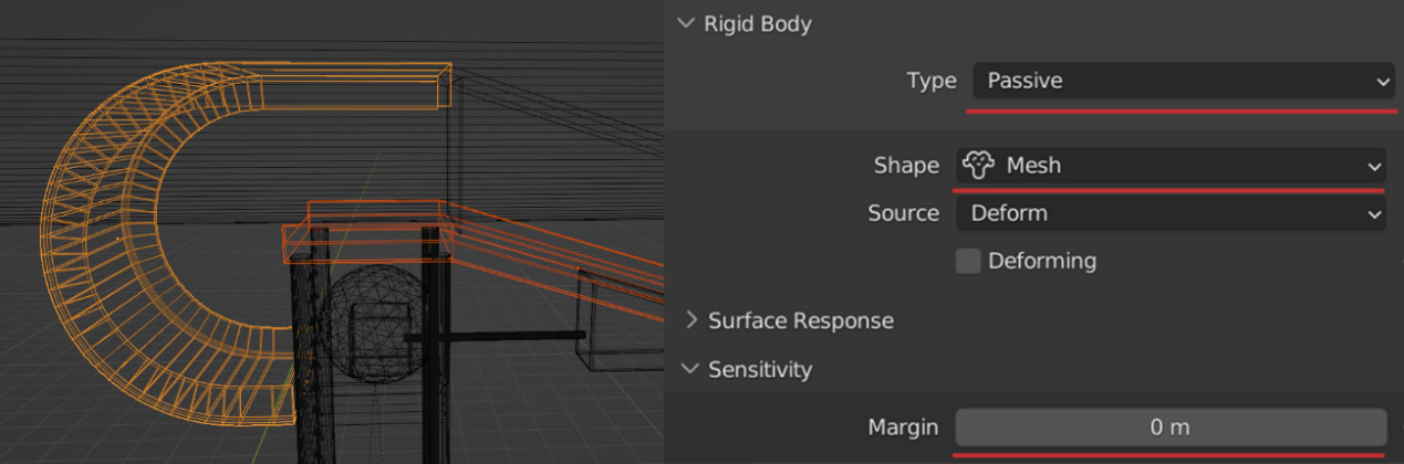
Figure 11.21 – The platform settings
- If the Sphere object does not make it all the way around the circle, you can set Friction in the surface responses of Platform 1 to around 0.1. This will make the sphere slide a bit more.
With that done, let’s move on to creating the Hinge constraints!
Creating the hinges
The last obstacle for the sphere to go through, before it crashes into the tower of cubes, is a series of walls that rotate using the Hinge constraint. To add this, do the following:
- Select the Wall 1 object and give it an Active rigid body.
- We want the Sphere to easily push the wall up, so let’s set Mass of Wall 1 to 0.001 kg.
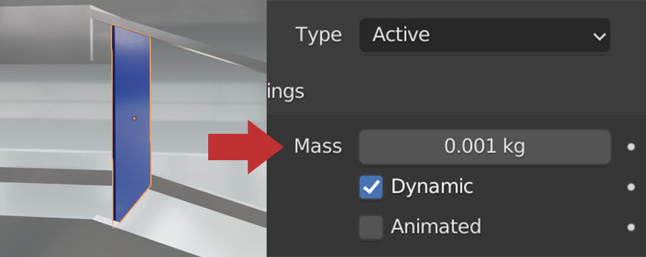
Figure 11.22 – The wall settings
- To create the constraint, select both Wall 1 and Platform 2. Just as before, let’s head up to the rigid body Object menu and select Connect. This will create an empty object that is used for the rotation point of the hinge! Then, change the constraint type to Hinge.
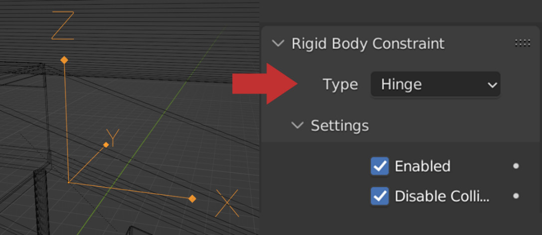
Figure 11.23 – The Hinge constraint
- The Hinge rotation is based on the Z angle of the constraint. So, if you want it to behave like a door, have Z (as shown in Figure 11.23) pointed up, and place it on the side of the wall. If you want the hinge point to be at the top, rotate the constraint so that the Z angle is pointed sideways, and then place it on the top of the wall (like in Figure 11.24).
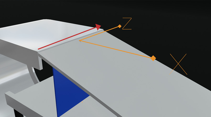
Figure 11.24 – Z angled down
For this tutorial, I will be rotating the constraint and placing it at the top of the wall. Feel free to change it however you like!
- At this point, you can duplicate both the wall and the Hinge constraint by pressing Shift + D and moving along the platform. This way, the sphere will go through multiple walls before falling out! Make sure that the walls aren’t hitting the lower platform, as this will cause issues in the simulation.
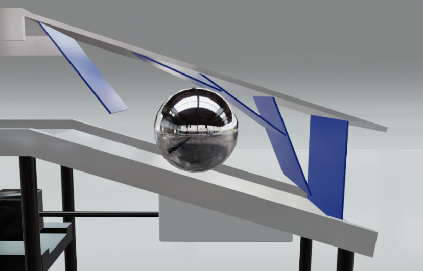
Figure 11.25 – Adding walls
And now, we get to the fun part of this project – collapsing the tower of cubes!
Collapsing the cubes
Adding physics to the 2,880 cubes that are piled up on the right side is very simple to do, so let’s go ahead and get started:
- First, go into Wireframe view by pressing Z. Make sure no other objects are selected, then drag a box about around all the cubes to select them.
- Go to the rigid body Object menu and select Add Active. This will give each cube an Active rigid body.
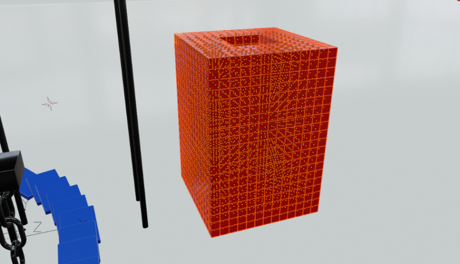
Figure 11.26 – Cubes selected
- Make sure to hold Shift and select one of the cubes so that it becomes the active object. Then, change the mass of the selected cube to 0.001 kg. This way, the sphere can crash through all of them very easily.
- The other important step is to turn on Deactivation in the Dynamics tab and check Start Deactivated.
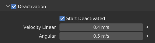
Figure 11.27 – Deactivation
Since the cubes have a slight gap between each of them, they will fall down just slightly at the start of the animation. This could cause some of the cubes to move around or fall. Turning Start Deactivated on will ensure that they don’t simulate until the sphere crashes into them.
- Now, we need to apply those changes to the rest of the objects. Head back up to the rigid body Object menu and select Copy From Active. This will copy all those changes we just made to the rest of the cubes instantly!
- Next, select each of the Column objects holding up the platforms and add a Passive rigid body to each! Now, the cubes will collide with them as well.
- Now, we can bake in the simulation! Remember to save your file again, then head back to the Scene Properties panel, and go down to the Rigid Body World tab. Inside the Cache tab make sure that the start frame is at 1 and the end frame is set at 500, and click Bake!
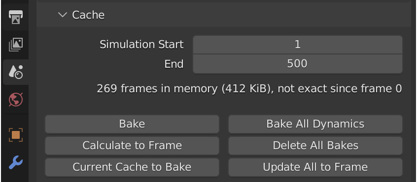
Figure 11.28 – The Cache panel
Once the bake is finished, you will be able to play the animation and see your simulation in real time! Play through it and make any changes you like. Maybe add some of your own obstacles to the scene!
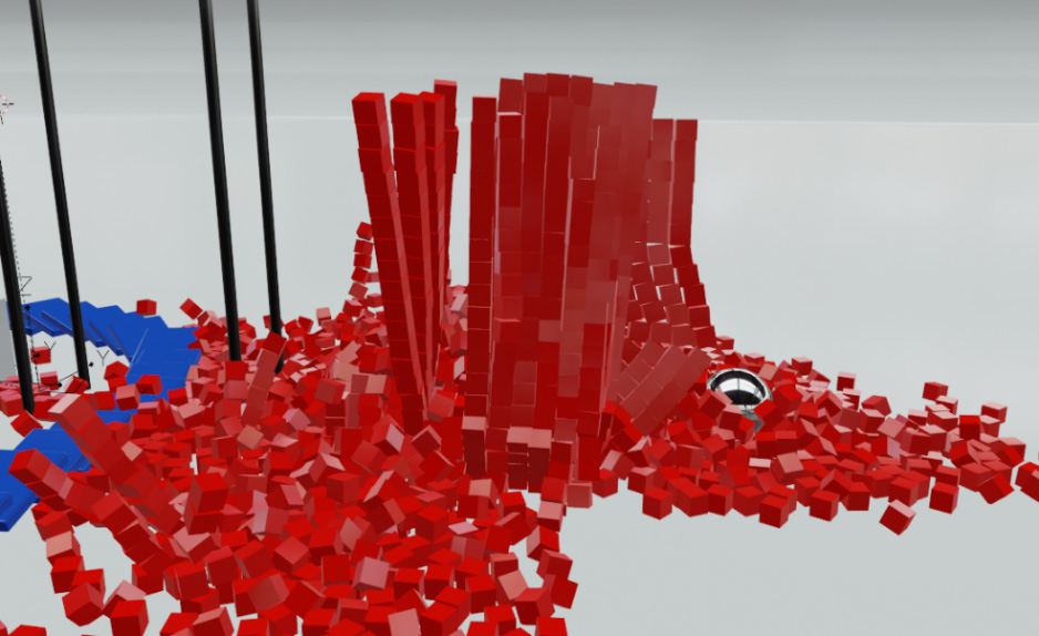
Figure 11.29 – Frame 384
You could have the sphere hit another button, releasing multiple spheres that crash into the cubes, or maybe add in some force fields to totally mess with the rigid bodies. Use your imagination and have fun with it! Once you are happy with the simulation, we can move on to the Camera animation!
Adding the Camera animation
For the Camera animation, we basically want to follow the progress of the simulation: starting out with the wrecking ball, moving up the elevator, following the Sphere around the half circle, and finally zooming out to see all the cubes collapse.
There are two main ways to move the camera around:
- You can select it and press G to move the camera manually.
- You can open the Properties panel by pressing N, and in the View tab, check Camera to View. This will allow you to move the camera around just as you would move around the viewport.
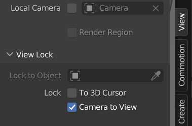
Figure 11.30 – Camera to View
You can use whatever method you prefer!
Now, let’s start animating the camera:
- Let’s start by going into the camera view by pressing 0 on the numpad or by going to View | Cameras | Active Camera.
- Next, select the camera and head over to the Object Data panel. Here, we can set Focal Length and what object to focus on. Check Depth of Field, and in Focus on Object, select Sphere.
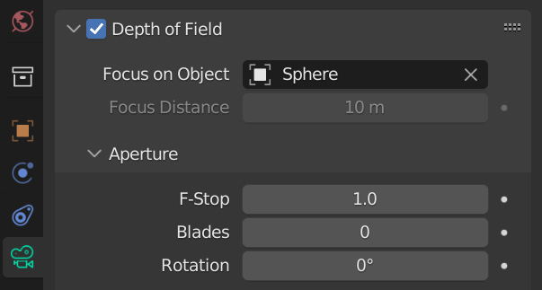
Figure 11.31 – Depth of Field
F-Stop controls how strong the depth of field will be. Lower values will make the background blurrier. Let’s set this to 1.0.
- From here, skip to Frame 1 and position the camera looking at the scene, press I, and select Location & Rotation to add a new keyframe.
- The next step is to play the animation for about 100–200 frames and position the camera where you like to add a new keyframe. Repeat this step until you complete the animation. Remember that you can always fine-tune the location of keyframes in the timeline if you don’t like how the animation looks.
If this part is a little tricky for you, you can download Rigid Body Course Project File.blend for reference here: https://github.com/PacktPublishing/Learn-Blender-Simulations-the-Right-Way/tree/main/Chapter11.
Now that the camera animation is done, let’s finish this scene by changing a couple of render settings in Eevee!
Setting up the render
In the last part of this tutorial, we will set up some Eevee settings and really make our animation stand out and look good:
- Head over to the Render panel and turn on Ambient Occlusion. This will add shadows to the corners of your objects and make them look much better. Factor controls the strength; let’s set this value to 2.00 so that we get darker shadows.
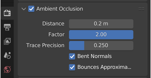
Figure 11.32 – Ambient Occlusion
The difference that Ambient Occlusion makes to the render is significant and can really help improve the look!
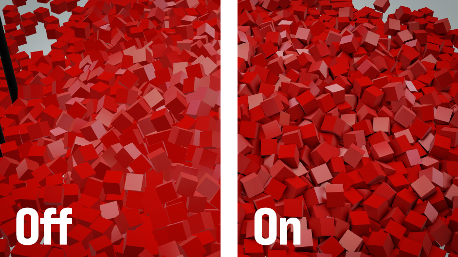
Figure 11.33 – Ambient Occlusion
- Enable Screen Space Reflections to get nice reflections in the glossy objects.
- Check Motion Blur as well. If you think the motion blur is a bit too strong, set the Shutter value lower.
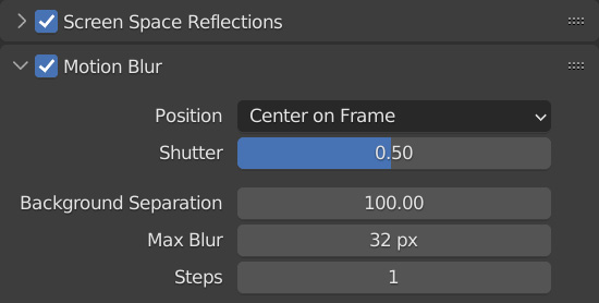
Figure 11.34 – The Motion Blur settings
And that is it! From here, we can render the animation! Head over to the Output panel and set a directory for where you want your animation to render. I recommend rendering this animation as an image sequence just in case of any crashes. If you don’t remember how this is done, refer to Chapter 4, Creating a Waterfall Using Mantaflow.
But there it is! We have now created an entire rigid body obstacle course! This doesn’t have to end here. You can add more obstacles or other things to the simulation. For example, you could add a Wind force field at the end to push all the red cubes off screen, or have the sphere object trigger something that causes multiple spheres to crash into the tower!
Another cool idea would be to animate the speed of the simulation when the sphere crashes into the tower. This could give a cool slow-motion effect! It’s all up to you and your imagination!
Summary
Hopefully, at this point, you have a good understanding of the rigid body simulation in Blender and feel confident about creating your own scenes and animations! You can always come back to this chapter or the previous one if you need a refresher.
Let’s do a quick recap to establish everything we learned today. First, we discussed how to create a wrecking ball using rigid bodies. From there, we added in a domino effect and animated a material. We learned about motor and hinge constraints and how to use them practically in a simulation. After that, we applied the rigid body to thousands of cubes and simulated them all at once. Finally, we set up the camera animation and render settings and exported the animation.
The rigid body simulation in Blender is very powerful and can be used to create many different scenes and animations. So, go play around with it and create your own simulations! This is also the end of part three of this book. In part four, we will discuss a topic that not a lot of people know about – dynamic paint!