In the previous chapter, we learned how to find the shortest path with obstacles in the virtual world. In this chapter, we will discuss the techniques for creating buildings and environments. We will discuss different common problems when putting buildings in the isometric world and the solutions to resolve them. We will also learn how large virtual worlds are divided into small parts and also extend our previous map editor to support buildings.
We will learn the following in this chapter:
- Adding buildings to world
- Sorting the buildings in isometric view
- Techniques of breaking down a large virtual world
- Connecting different parts of the world
- Some tips and tricks when creating the environments
- Implementing a more powerful map editor to design the virtual world
Similar to drawing the avatars, there are several ways to draw the isometric buildings. We can draw them in any graphical editing tool such as Photoshop or Flash. We can also model them in any 3D software.
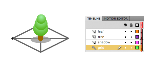
When drawing in Flash, we often put some isometric tiles as a guide to keep the correct orthographic projection. The size of the building is based on the side length of the tile. A building can occupy a group of contiguous tiles. For example, a tree occupies a 1x1 tile of the map, a fountain occupies 3x3 tiles, and a building may occupy 2x5 tiles. The following graph shows a hand-drawn isometric tree in Flash with a tile as guide:
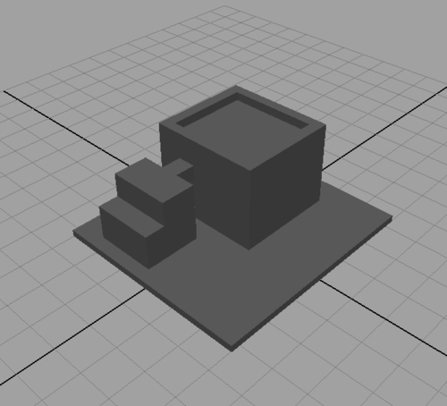
Another common method of drawing buildings is by using 3D modeling tools. Similar to creating the avatar graphics by 3D modeling tools, we can set up an orthographic camera in front of the buildings with the viewing angle matching the Flash virtual world. The advantage of using 3D modeling tools is that we can put texture on the building easily without considering the transformation of the isometric projection.
We will show an example on how to output an isometric building in different directions from 3D software. Although every 3D software comes with different interface and commands, the general steps of outputting the building from 3D software to isometric project are almost the same.
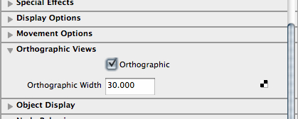
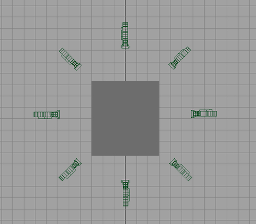

After the eight cameras are set up, we can also write scripts to generate the render of all eight cameras instead of clicking the "render" button eight times per frame. The degree of the downward rotation of the cameras can also be adjusted to fit the isometric view of the map in Flash.
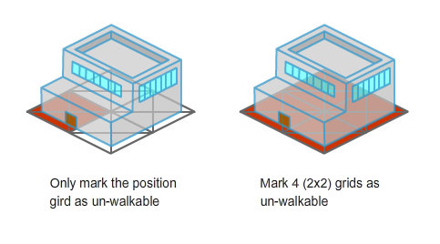
We cannot walk on a building in the real world. In virtual world, we need to prevent the avatars from walking on the buildings by using walkable map.
Walkable map is a two-dimensional array with the same size of the terrain map. Each tile of the walkable map declares if avatars can walk on those tiles or not. When we put buildings on the virtual world, we need to mark the tiles that the building has occupied as unwalkable in the walkable map.
The virtual world needs to know all types of buildings in order to draw them and show relative information. The information is basically the ID, name, the length of the side it occupies, and the graphical reference of the class name.
In this example, we will load the data of the buildings externally from an XML file. The buildingData.xml is in the following XML structure:
<buildingData>
<building id='1'>
<size>1</size>
<name>tree</name>
<classname>Tree1</classname>
</building>
<building id='2'>
<size>4</size>
<name>Hotel</name>
<classname>BuildingHotel</classname>
</building>
</buildingData>
We use URLLoader to load this external buildingData.xml.
_xmlLoader = new URLLoader();
_xmlLoader.addEventListener(Event.COMPLETE, init);
_xmlLoader.load(new URLRequest('data/buildingData.xml'));
After the building data is loaded, we put them inside an array with the building ID as key for quick access later.
private function init(e:Event):void {
_xml = new XML(e.target.data);
for (var i:int = 0; i < _xml.building.length(); i++) {
var buildingID:int = _xml.building[i].attribute('id'),
_buildings[buildingID] = new BuildingData();
_buildings[buildingID].buildingID = buildingID;
_buildings[buildingID].size = _xml.building[i].size;
_buildings[buildingID].name = _xml.building[i].name;
_buildings[buildingID].classname = _xml.building[i].classname;
}
}
Note
The document and example of using the XML class in ActionScript 3 can be found in the following link: http://www.adobe.com/livedocs/flash/9.0/ ActionScriptLangRefV3/XML.html.
We need to be careful of the security problem when putting all building data into an external file. Raw data such as map and buildings should not be accessible directly by users. Players can easily find cheats, tricks, shortcuts, and even hack the virtual world with the access of the raw data. We can deny the public access by putting the XML files outside the web server public folder or adding .htaccess limitation on the file. One advanced way is to load this kind of external raw data via socket connection instead of the traditional URLLoader class. We should also validate each player's movement requests in server-side before putting the virtual world in production.
We need to specify where and which building to show in a map. The following XML shows the building information structure inside the mapdata.xml. There are three fields in every building entry. They are building type and the X/Y in position in map. The building type refers to the ID in our building definition XML file.
<map>
<name>Sample Map</name>
<width>30</width>
<height>30</height>
<terrain><![CDATA[...]]></terrain>
<buildings>
<building>
<type>2</type>
<x>25</x>
<y>18</y>
</building>
<building>
<type>1</type>
<x>16</x>
<y>17</y>
</building>
...
</buildings>
</map>
In order to display the buildings, we loop through these building nodes when drawing the map. A notable code is the use of getDefinitionByName. This method is used to get the class reference from string of building's name in runtime. Then we can create a movie clip instance of the building from this class reference. Also, we need to set the tiles that are occupied to unwalkable.
for(i=0; i<_xml.buildings.building.length(); i++) {
var buildingXML:XML = _xml.buildings.building[i];
var ClassReference:Class = getDefinitionByName (_buildings[buildingXML.type].classname) as Class;
var newMC:MovieClip = (new ClassReference as MovieClip);
_mapHolder.addChild(newMC);
newMC.id = Number(buildingXML.type);
var ix:int = int(buildingXML.x);
var iy:int = int(buildingXML.y);
var screenBuildingCoord:Point = i2sLocal(ix,iy);
newMC.x = screenBuildingCoord.x-_gridWidth/2;
newMC.y = screenBuildingCoord.y;
var size:int = _buildings[newMC.id].size;
for(var ii:int = iy-size+1; ii<=iy; ii++){
for(var jj:int = ix; jj<ix+size; jj++){
_astarMap.setCell(ii,jj,_astarMap.CELL_FILLED);
_walkableMap[ii][jj] = 0;
}
}
}
It not only marks the position of the building as unwalkable but also needs to mark those surrounding tiles as unwalkable by the building size.