
The first thing we will tackle is the functionality of the ESP8266. We will look at the features and functions of the ESP8266, and learn about all the available GPIO pins and how we can use them to read and write digital signals.
The ESP8266 chip provides a self-contained, standalone Wi-Fi networking solution that allows you to host applications and to provide a Wi-Fi network that you can use to transfer data and instructions in your projects.
In normal use, the ESP8266 boots up directly from an external flash memory. It also has a cache that improves the performance of the system and reduces the amount of memory needed during operation.
The ESP8266 can also be used as a Wi-Fi adapter. In this case, the chip provides wireless Internet access to a microcontroller-based project through either the CPU AHB bridge or UART interface.
The on-board processing and storage capabilities of the ESP8266 enable easy integration with sensors and other devices via the GPIO pins. Moreover, the ESP8266 requires little to no external circuitry because of its on-chip integration, which includes power management converters and antenna switch balun. This makes it small and ideal for compact projects.
In addition to all those features, the ESP8266 has some sophisticated system-level features that include adaptive radio biasing for low-power operation, energy-efficient VoIP due to rapid sleep/wake switching, advanced signal processing and radio co-existence, and spur cancellation features that prevent cellular and Bluetooth interference.
The main features of the ESP8266 can be listed as:
- 802.11 b/g/n protocol
- Integrated TCP/IP protocol stack
- Soft-AP, Wi-Fi direct (P2P)
- Integrated power amplifier an management units, PLL, TR switch, regulators, LNA, switch, matching network, and balun
- Integrated 32-bit low-power CPU used as the application processor
- Supports antenna diversity
- Supports UART, SPI, and SDIO 2.0 interfaces
- 2 ms wake up and transmit interval
- Power down leakage current of less than 10 µA
- Standby power of less than 1.0 mW
- Output power of +19.5 dBm when using 802.11 mode
- STBC, 2x1 MIMO, 1x1 MIMO
- A-MSDU and A-MPDU aggregation
To understand the ESP8266 pin configuration, we are going to look at the ESP-12 module. This is because it is the same module that is used on the Adafruit feather HUZZAH ESP8266 Wi-Fi board that we are using for our exercises, as explained in Chapter 1, Configuring the ESP8266. The following diagram shows the ESP-12 pin configuration:

The ESP-12 module pins are connected to a more breadboard-friendly pin configuration on the Adafruit ESP8266 board. The pin configuration of the Adafruit board is shown in the following diagram:
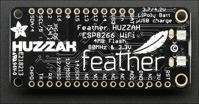
The pins on the Adafruit ESP8266 module can be grouped into several categories.
- BAT: Positive voltage from the Li-Po battery that is connected to the JST jack
- GND: Common ground for the power and logic
- USB: Positive voltage from the micro USB port on the board
- 3V: Output voltage from the on-board 3.3V regulator, which supplies a maximum of 500 mA
- EN: 3.3V voltage regulator enable pin; to disable the 3.3V voltage regulator, connect this pin to GND
The serial pins are labelled RX (receive) and TX (transmit). Note that those pins can also be used for I2S communications. They are used for serial communication and boot loading. The RX pin is the input pin and is 5V compliant, since it has a level shifter. The TX pin is the output from the module and has a 3.3V logic. The two pins are connected to the CP2104 USB to serial converter and should be left disconnected unless you really want to use them.
The ESP8266 module comes with both I2C and SPI interfaces, which enable you to communicate with sensors, outputs, and devices that use these interfaces. Though this is done through bitbanging, it works just as well as it does on the Arduino.
Hypothetically, any GPIO pin on the ESP8266 can be used for I2C and SPI, but the current library for the Adafruit ESP8266 uses the following pins:
- For I2C:
- I2C SCL – GPIO 5
- I2C SDA – GPIO 4
- For SPI:
- SPI SCK – GPIO 14
- SPI MISO – GPIO 2
- SPI MOSI – GPIO 13
The Adafruit HUZZAH ESP8266 has nine GPIO pins that you can use. They are: 0, 2, 4, 5, 12, 13, 14, 15, and 16.
They all have a 3.3V logic level and are not 5V compatible. The maximum current that can be drawn from one pin is 12 mA. The pins are general purpose and can be used for input as well as output. Additional functions of the pins are explained following:
- GPIO 0 does not have an internal pullup resistor and is connected to a red LED which it controls. In addition to this, the pin is used to set the ESP8266 into bootloader mode. This is achieved by pulling the pin low during power-up.
- GPIO 2 has a pullup resistor and is connected to the blue LED, that is close to the Wi-Fi antenna. It is used to detect boot mode and as an output to control the blue LED.
- GPIO 15, the same as pin 2, is used to detect boot mode. There is a pulldown resistor connected to it. Always ensure this pin isn't pulled high during power-up. It can only be used as an output.
- GPIO 16 is used to wake up the module from deep sleep mode. It is advisable to connect it to the reset pin.
There is only one analog pin on the ESP8266 board. It is labelled ADC. The pin can read a maximum voltage of approximately 1.0V. If the voltage you want to read is higher than 1.0V, you have to use a voltage divider to convert it to a 0-1.0V range.
The ESP8266 module reads digital signals from inputs and writes digital signals to outputs via the GPIO pins. Since all the GPIO pins have a logic voltage of 3.3V, it is important to ensure that any input signal to the pins is between 0V and 3.3V.
The GPIO pins usually read or write two kinds of digital signal: 0s and 1s. 0s represents voltages between -0.3V and 0.825V, while 1s represents voltages between 2.475V and 3.3V. Therefore, whenever you read a digital pin that is connected to a voltage above 2.475V, you get a 1 (high signal), and when you read a pin that is connected to a voltage less than 0.875V, you get a 0 (low signal), and the same applies to outputs.