
In this recipe, we will look at automated light control using M2M. We will work on a project that will turn a light source on or off, depending on the light intensity of the surrounding environment. Two ESP8266 boards will be used to accomplish this. One of them will have a light dependent resistor, and the other will have a relay connected to it.
You will need the following hardware components:
- ESP8266 board
- USB cable
- Light dependent resistor (LDR) (https://www.sparkfun.com/products/9088)
- 10 kΩ resistor
- Relay module (http://www.dx.com/p/arduino-5v-relay-module-blue-black-121354)
- Breadboard
- Jumper wires
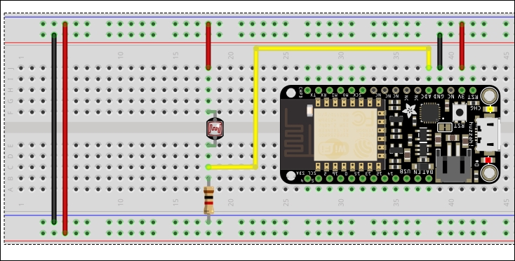
Connect the analog input of the ESP8266 board to an LDR connected to a 10 kΩ resistor in a voltage divider circuit, as shown in the following image. This setup is going to act as the input for the system:
As for the output of the system, connect a relay to GPIO2 of the other ESP8266 board. The connection will be via an NPN transistor such as the 2N222, and a diode such as 1N4001 will be placed across the relay coil pins to protect the board from back EMF. The relay circuit should look like this:
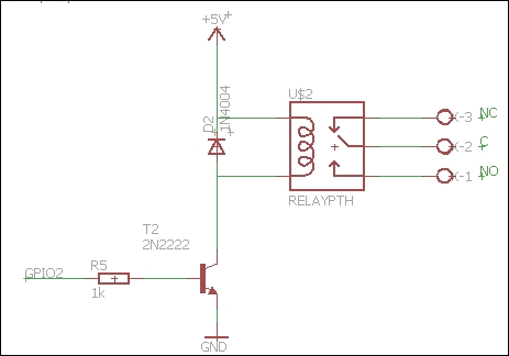
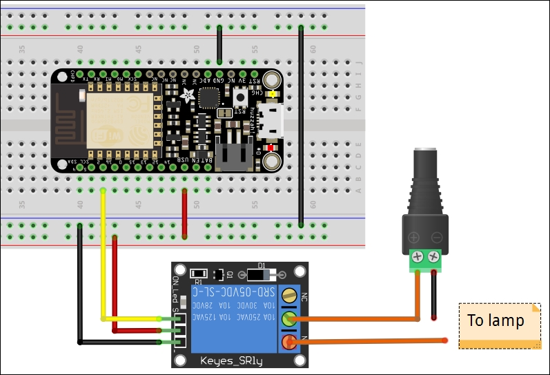
However, in this recipe, you won't have to connect an NPN transistor and the diode in your setup, as they are already provided on the relay module that you are going to use. You will connect three wires from your ESP8266 board to the relay module. The wires will be GPIO2, GND, and USB power (5V). This will simplify the hardware connection, as shown in the following figure:
Configure the input setup, which comprises the LDR sensor and an ESP8266 board, to monitor the light intensity in the surroundings. If the reading on the analog pin goes below 512, the ESP8266 should send the value 1 to the MQTT broker under a topic called lightControl. If the value goes above 512, the ESP8266 board should send the value 0 to the MQTT broker under the same topic.
In addition to that, set up the ESP8266 to subscribe to a topic called relayState that will return the state of the relay switch from the output setup.
The code for the sensor setup is as follows:
- Include the libraries:
#include <ESP8266WiFi.h>
#include <PubSubClient.h>
- Provide the SSID and
passwordof your Wi-Fi network:// Update these with values suitable for your network. const char* ssid = "your_ssid"; const char* password = "your_password";
- Provide the MQTT server and the topic that your device will be publishing to, and the topic that your device is subscribed to:
const char* mqtt_server = "broker.mqtt-dashboard.com";
const char* topicPub = "lightControl";
const char* topicSub = "relayState";
- Create the
Wi-Fi clientandMQTT clientobjects:WiFiClient espClient; PubSubClient client(espClient);
- Variables to be used in the program:
char msg[50];
boolean triggerState = false; // type of trigger 0 or 1
boolean sent = false; // controls when to publish
- Initialize serial port, connect to the Wi-Fi hotspot and then set up the MQTT server and
callback:void setup() { Serial.begin(115200); setup_wifi(); client.setServer(mqtt_server, 1883); client.setCallback(callback); } - Function that connects the ESP8266 board to the Wi-Fi hotspot:
void setup_wifi() { delay(10); // We start by connecting to a WiFi network Serial.println(); Serial.print("Connecting to "); Serial.println(ssid); WiFi.begin(ssid, password); while (WiFi.status() != WL_CONNECTED) { delay(500); Serial.print("."); } Serial.println(""); Serial.println("WiFi connected"); Serial.println("IP address: "); Serial.println(WiFi.localIP()); } - This is the
Callbackfunction that handles the incoming data from the topic the device has subscribed to:void callback(char* topic, byte* payload, unsigned int length) { Serial.print("Message arrived ["); Serial.print(topic); Serial.print("] "); for (int i = 0; i < length; i++) { Serial.print((char)payload[i]); } Serial.println(); } - Function that connects the ESP8266 client to the MQTT server and sets up the topic to
publishto, and the topic to subscribe to:void reconnect() { // Loop until we're reconnected while (!client.connected()) { Serial.print("Attempting MQTT connection..."); // Attempt to connect if (client.connect("ESP8266Client")) { Serial.println("connected"); // Once connected, publish an announcement... client.publish(topicPub, "0"); // ... and resubscribe client.subscribe(topicSub); } else { Serial.print("failed, rc="); Serial.print(client.state()); Serial.println(" try again in 5 seconds"); // Wait 5 seconds before retrying delay(5000); } } } - Check sensor input and set
triggerto the correct state:void loop() { // toggle the state if push button is pressed if(analogRead(A0) < 512 && !triggerState){ triggerState = true; // set trigger high sent = false; // allow publishing } else if(analogRead(A0) >= 512 && triggerState){ triggerState = false; // set trigger low sent = false; // allow publishing } - Connect to the MQTT broker if
connectionhas been lost:if (!client.connected()) { reconnect(); //establish connection to MQTT } client.loop(); - Publish
triggerif its state has changed:if (!sent) { snprintf (msg, 50, "%ld", triggerState); // generate message Serial.print("Publish message: "); Serial.println(msg); client.publish(topicPub, msg); // publish sent = true; } }
Configure the output setup to subscribe to the lightControl topic on the MQTT server. It will be listening for any incoming data from the input setup. The incoming data will either be a 1 or a 0. If it is a 1, the ESP8266 board in the output setup will set the GPIO2 pin high to close the relay. If the incoming data is 0, the ESP8266 will set the GPIO2 pin low, opening the relay. Configure the output setup to publish the current state of the relay to a topic called relayState. The input setup will be subscribed to this topic for updates on the current state of the relay. The code will look like this:
- Include the libraries:
#include <ESP8266WiFi.h>
#include <PubSubClient.h>
- Provide the SSID and
passwordof your Wi-Fi network:// Update these with values suitable for your network. const char* ssid = "your_ssid"; const char* password = "your_password";
- Provide the MQTT server and the topic that your device will be publishing to, and the topic that your device is subscribed to:
const char* mqtt_server = "broker.mqtt-dashboard.com";
const char* topicPub = " relayState";
const char* topicSub = " lightControl";
- Create the
Wi-Fi clientandMQTT clientobjects:WiFiClient espClient; PubSubClient client(espClient);
- Variables to be used in the program:
char msg[50];
char incoming = '0'; // holds incoming character
boolean sent = false; // controls publishing
- Configure the built-in LED pin as an output, initialize serial port, connect to the Wi-Fi hotspot, and then set up the MQTT server and
callback:void setup() { pinMode(2, OUTPUT); // Initialize GPIO2 pin as an output digitalWrite(2, LOW); // set pin low Serial.begin(115200); setup_wifi(); client.setServer(mqtt_server, 1883); client.setCallback(callback); } - Function that connects the ESP8266 board to the Wi-Fi hotspot:
void setup_wifi() { delay(10); // We start by connecting to a WiFi network Serial.println(); Serial.print("Connecting to "); Serial.println(ssid); WiFi.begin(ssid, password); while (WiFi.status() != WL_CONNECTED) { delay(500); Serial.print("."); } Serial.println(""); Serial.println("WiFi connected"); Serial.println("IP address: "); Serial.println(WiFi.localIP()); } Callbackfunction that handles the incoming data from the topic the device has subscribed to:void callback(char* topic, byte* payload, unsigned int length) { Serial.print("Message arrived ["); Serial.print(topic); Serial.print("] "); for (int i = 0; i < length; i++) { Serial.print((char)payload[i]); } Serial.println(); // Switch on the LED if an 1 was received as first character if ((char)payload[0] == '0'&& incoming != (char)payload[0]) { digitalWrite(2, LOW); // open relay incoming = (char)payload[0]; sent = false; // allow publishing } else if ((char)payload[0] == '1'&& incoming != (char)payload[0]) { digitalWrite(2, HIGH); // close relay incoming = (char)payload[0]; sent = false; // allow publishing } }- Function that connects the ESP8266
clientto the MQTT server and sets up the topic topublishto, and the topic to subscribe to:void reconnect() { // Loop until we're reconnected while (!client.connected()) { Serial.print("Attempting MQTT connection..."); // Attempt to connect if (client.connect("ESP8266Client")) { Serial.println("connected"); // Once connected, publish an announcement... client.publish(topicPub, "low"); // ... and resubscribe client.subscribe(topicSub); } else { Serial.print("failed, rc="); Serial.print(client.state()); Serial.println(" try again in 5 seconds"); // Wait 5 seconds before retrying delay(5000); } } } - The
voidloopsection will run the previous functions. It will reconnect the ESP8266 to the MQTT when it disconnects andpublisha message to the topic every time the incoming data changes:void loop() { if (!client.connected()) { reconnect(); //establish connection to MQTT } client.loop(); if (!sent) { snprintf (msg, 50, incoming == '0'?"OFF":"ON"); Serial.print("Publish message: "); Serial.println(msg); client.publish(topicPub, msg); sent = true; } }
Replace your_ssid and your_password in the code to match the credentials of your Wi-Fi network. Upload the sketches to their respective ESP8266 boards and power them.
The ESP8266 input setup monitors light intensity using an LDR sensor. When the light in the surrounding environment is dim, indicating that night is approaching, the input setup sends a trigger to a topic called lightControl in an MQTT broker. The output setup reads data from that topic and turns the light on or off, depending on the received trigger. When the trigger is 0, the bulb is turned off, and when it is 1, the bulb is turned on.
Change the sketch so that the lights go on when it is bright outside and go off when it is dim outside.