
Direct current
AC and DC signals
We often hear electrical signals classified as ‘AC’ or ‘DC’. These abbreviations stand for the terms ‘alternating current’ and ‘direct current’, but they are applied as much to voltages as to currents. In this chapter we will talk about DC. Given that we understand Ohm’s Law, stated in Chapter 2, we have actually covered most of what ground there is. We will also introduce the term ‘power’ and consider its implications, which are important.
Direct current
A DC current is one which flows in one direction only. If we were to connect a resistor between the two terminals of a battery a DC current would result. For conventional current, it would flow from the positive terminal to the negative and have a magnitude, determined by Ohm’s Law, of I = V/R. Similarly, we would refer to the voltage across that battery as a’DC voltage’.
One application of DC is supplying power to an electronic circuit. The output from a power supply is often called the ‘power rail’ or just ‘the rail’. The supply could be a separate circuit, operating from AC mains, or batteries. Virtually all circuits require one or more DC voltages to operate. A very common arrangement is to supply two rails with equal and opposite voltages, perhaps one of +15 V and one of −15 V. Then there will be three power rails; 0 V, used as a reference point for the whole circuit, and +/−15 V, used to supply power. Computer circuits often use a single rail of +5 V, perhaps with one or more other voltages used by the circuits which interface the computer to the outside world.
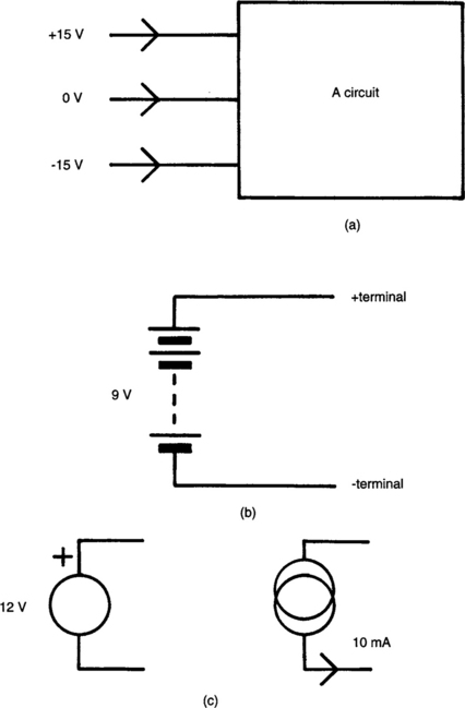
Circuit symbols for DC voltages and currents come in many flavours. Figure 3.1 shows some. You may just get lines, as in (a), with an indication of what the voltage or current is. (In a block diagram, like this example, the arrow may not follow the direction of current flow; it can just show that the supply is an ‘input’ to the circuit.) The symbol for a battery is shown at (b). The two general symbols for a voltage and current source are shown in (c). These would both indicate an unspecified device or circuit block; the intent is to indicate that a source exists at that point in the circuit, to help you see what is going on without actually telling you what physical devices to expect.
Calculations on DC quantities
Addition, subtraction, multiplication and division can be performed on DC voltages and currents simply by performing the relevant operation on the numbers, paying due regard to their signs.
Resistors in DC circuits
There is hardly anything to say about this; they obey Ohm’s Law, as already described. Also you should make sure that the rated power dissipation is not exceeded, as we discuss later.
Capacitors in DC circuits
If we put a DC voltage across a capacitor an instantaneous (‘transient’) current flows while it charges to the voltage. Thereafter no current flows as long as the voltage remains steady, with the exception of the leakage current that was discussed in Chapter 2. Capacitors are often used to isolate one part of a circuit from another to DC, while allowing AC signals to pass (as a ‘DC block’).
If we make a steady DC current flow into a capacitor (from a current source) the result is a ramp voltage across it. From Eqn (2.5), the ramp has a slope of:
![]() is the slope of the ramp in volts per second, I is the current in amps and C the capacitance in farads. This is a common method of making ramp generator circuits.
is the slope of the ramp in volts per second, I is the current in amps and C the capacitance in farads. This is a common method of making ramp generator circuits.
Inductors in DC circuits
An ideal inductor would be a short to DC. A real one appears to be a resistor with the value of the internal resistance of the inductor (hopefully very low). When DC current is passed through the inductor we get a transient voltage (the back EMF mentioned in Chapter 2). Thereafter the voltage will be small. Because of this, inductors are sometimes used to block AC but pass DC (as a ‘choke’).
Placing a steady DC voltage across an inductor causes the current waveform to be a ramp (in the same way that a DC current in a capacitor causes a ramp voltage). The slope of the current waveform is, from Eqn (2.8):
(Did you notice how capacitors and inductors tend to do similar but opposite things to AC and DC voltages and currents?)
Power in DC circuits
Why do we worry about power dissipation?
As we saw in Chapter 2, connecting a voltage across a resistor causes a current to flow. The amount of the current depends on the value of the resistor; the lower the more current. In physical terms, this means that the average electron speed through the resistor is higher. Thus an electron making its way through strikes atoms in its path harder, and creates more heat. (We never have to worry about the electron speed, just the value of current; this is just a reminder of the physical process taking place.) The heat will be lost to the air, hopefully. How quickly the heat can dissipate depends mostly on physical structure of the resistor. If it cannot get away more quickly than it is generated, then the temperature will rise until it reaches a point where it destroys the component. Resistors go brown at this point, start to smell, and eventually go open circuit (sometimes catching fire in the process). Then you change them. Watching miniature resistors (1/8 W or 1/4 W types) catch fire isn’t too bad, may even be mildly entertaining. (I have known heavy smoking engineers to use the trick to get a light in the middle of the night when the garage is shut, though I don’t recommend the chemical content for your health.) Anything larger than that should definitely be avoided.
So that we can avoid this situation, resistors always have a ‘maximum power rating’. Power is measured in watts(W). The power rating of a resistor might be anything from less than 0.1 W, for very small surface-mounted devices, to 100 W or more, for large, heavy devices intended to be bolted to ‘heatsinks’ (pieces of metal designed to radiate and make heat dissipate more quickly). On opening up pieces of electronic equipment we may sometimes see resistors which have obviously been overheating; the painted exterior may be brown and cracked. This may be the cause of the fault that we are investigating or an indication that some other fault is causing excessive current to flow. Sometimes it is an indication that the designer of the equipment wasn’t as meticulous as he might have been. A resistor run continually at its maximum power may show signs of burning without misfunctioning, but the long-term reliability is likely to be reduced.
I have tried to follow a ‘rule-of-thumb’ which I learnt from an experienced engineer early in my career; to try not to run components continually at more than about one-third to one-half of their rated power. Running them at maximum for a short duration is generally OK; the device has time to cool off. If in doubt, prototype and use common sense. If it goes brown, you are being a bit ambitious.
Power calculation in DC circuits
How do we calculate the power dissipation in a resistor? Power is defined as the rate of energy dissipation, or:
where P is the power in watts, J is the energy in joules and t is the time in seconds. From Eqn (1.2):
Substituting into Eqn(3.3), we get:
From Eqn (1.1):
Like Ohm’s Law, this gets used a lot, and you need to know it. (The derivation is just for interest’s sake.) The result is important enough to be restated, and learnt, in its two other forms:
and:
Example 3.1: A resistor of 10 Ω has a voltage of 3 V across it. How much power does it consume?
and using Eqn(3.4a):
Often we use two equations which we can get from Ohm’s Law and Eqn (3.4a) by a little algebraic substitution:
and
These enable us to answer questions like that posed in Example 3.1 in one step. Using Eqn (3.4d):
The business of using components within their maximum power rating quickly becomes fairly intuitive. For a circuit working from low voltages, say +/−15 V DC, the maximum available voltage is 30 V. Our workshop resistor kit may contain miniature resistors all rated at 1/8 W. This enables us to calculate a value of resistor above which we cannot, no matter how we try, exceed the rated power.
Example 3.2: For the circumstances which we just described, what is the ‘minimum’ value, following the ‘half-rated-power’ rule-of-thumb?
Our threshold value of resistance is:
-or say 15 kΩ.
This does not mean, of course, that we won’t use any components of less than this value; but that above this value we can dot them around without worrying about power rating. At values around 15 k Ω, we only need worry if they spend a lot of time strapped across the power rails, which very few will. Even for low values, we will tend only to get the calculator out when we know that the resistor has a large voltage across it.