ADVANCED DIGITAL SET-TOP BOXES
For cable, terrestrial, and satellite companies, home networking is another opportunity to increase the use and revenue streams of broadband interactive data and video services. The deployment of digital TV and interactive services is already under way in various locations around the globe. Central to this migration from analog to digital broadcasting is a small device called a set-top box. These set-top boxes will retail for about $250 and provide consumers with a much better video quality compared with today's existing analog systems. Other capabilities of these devices include:
Advanced programming information for 7 days
Embedded modems that will enable a television to be used as a display for Internet access
Compression so that 6 to 12 compressed digital TV signals can be carried in the same amount of frequency as one TV signal without digital compression
An Ethernet plug on the back of the set-top box so that computers or home routers can be connected to the set-top box
Video on demand, so users can order premium movies from their set-top boxes
The Federal Communications Commission (FCC) has mandated that set-top boxes be available for retail sale by July of 2000. Let's take a closer look at this gateway device.
Basic Concepts
When you think of a set-top box, picture a TV set and a black box connected to the set with lots of wires. The true picture of a digital set-top is one of a complex electronics device comprised of many hardware and software components.
It is usually connected to your TV and the cable connection on the wall. Your local cable, terrestrial, or satellite operator normally installs these devices. This may change next year when set-top boxes enter retail stores across the globe. Set-top boxes can also be described as types of computers that translate digital signals into a format that can be viewed on a television screen.
The main features of a set-top box may be classified as follows:
Decodes the incoming digital signal
Verifies access rights and security levels
Displays cinema-quality pictures on your TV
Outputs digital surround sound
Processes and renders Internet and interactive TV services
Under the Hood
At the moment, every network operator has unique set-top box requirements; therefore, manufacturers are forced to have a distinct design for each operator. The architecture we describe in this chapter is for a fairly advanced set-top box and is not specific to any network operator or set-top box manufacturer.
The physical components may be roughly divided into the following categories:
System board
Tuner(s)
Modulator and demodulator
Demultiplexer and decryptor
Decoders
Graphics processor
CPU and memory
Storage devices
Physical interfaces
Physical characteristics
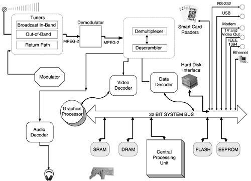
If we look more closely at the anatomy of a digital set-top in Figure 9.2, you will notice that the hardware architecture is very similar to a standard desktop multimedia computer. This figure shows an expanded and simplified view of a set-top box gateway device.
System Board
If you were to open up a digital set-top box and look inside, you would see a large printed circuit board—the system board. The system board is made of a fiber glass sheet that has miniature electronic circuitry embedded in it.
Tuners
The tuner module is available for accessing QAM-, OFDM-, and QPSK-based networks. Tuners can be divided into two broad categories:
Broadcast in-band (IB) tuner— Once the signal arrives from the physical transmission media, the IB tuner isolates a physical TV channel from a multiplex of channels and converts it to baseband.
Figure 9.2. Architecture of a digital set-top box

Out of band (OOB) tuner— This type of tuner facilitates the transfer of data between an in-home system and broadband network servers. Implementations of the OOB tuner tend to operate within the 100 to 350 MHz frequency band.
Modulator and Demodulator
The baseband output signal from the tuner is forwarded to a demodulator. The function of the demodulator is to sample the incoming signal and convert it to a digital bitstream. The bitstream contains video, audio, and possibly some data. Once the bitstream has been recovered, it is checked for errors and forwarded to the demultiplexer. The modulator reverses the actions of a demodulator and is used by the set-top box to deliver a signal to the return path tuner.
Demultiplexer and Decryptor
A standard MPEG-2 data stream will consist of a number of uniquely identified data packets. MPEG-2 uses an identifier called a Packet ID (PID) that identifies a packet as containing a particular format of data—audio, video, or interactive services. European and Japanese TV operators have agreed on 32 unique PIDs for identifying various data formats. The demultiplexer is an application-specific integrated circuit (ASIC) chipset that examines every PID and selects, decrypts, and forwards particular packets to a specific decoder. For example, all packets with the data PID will be forwarded to the data decoder.
The decryption unit is based on a complex algorithm that prevents unauthorized users from viewing programs or accessing Internet-based services. The exact details of the decryption process are operator-specific and are shrouded in secrecy.
Decoders
A digital set-top box will normally contain three separate decoders for converting the digital bitstream into a format that can be heard and viewed by the subscriber. A video decoder will transform the video packets into a sequence of pictures, which are displayed on the TV monitor. Video decoder chips are capable of formatting pictures for TV monitors with different screen resolutions and support for still pictures. The compressed audio bitstream is sent to an audio decoder for decompression. Once the MPEG-2 bitstream is decompressed, it is presented to a set of speakers on the network. Current digital set-tops are capable of supporting the following audio modes:
Mono and dual channel
Stereo
Joint stereo
The last type of decoder is used to forward the data to a high-speed interface port that is connected to the in-home network.
Graphics Processor
The main purpose of a graphics processor is to render a range of Internet file formats and proprietary interactive TV file formats.
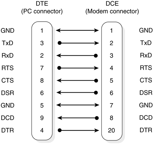
Figure 9.3. Standard 9-pin RS232 connectivity

RS232 Serial Interface
Set-top boxes normally come equipped with the RS232 standard serial interface. The interface uses a D connector with nine pins and allows connectivity to serial printers, computers, and standard telephone modems. Figure 9.3 illustrates the pin-outs of a connection between a set-top box and a telephone modem.
Central Processing Unit
The CPU (Central Processing Unit) is the brains of the set-top and is housed in a single chip called a processor. In terms of functionality and processing, the CPU is the most important element of a digital set-top box. Functions typically provided by a processor include:
Initialization of the various set-top hardware components
Processing a range of Internet and interactive TV applications
Monitoring and managing hardware interrupts
Fetching data and instructions from memory
Running various programs
Memory Configuration
Just as a computer needs memory to function, a set-top also requires memory to store and manipulate instructions that are issued by the subscriber. Memory comes in chip format and is comprised of millions of integrated circuits (ICs). These chips are connected to the system board inside the set-top box. Most elements within the set-top box will require memory to perform various tasks. The graphics engine, video decoder, and descrambler all require a certain amount of memory to fulfill their specific functions within the set-top box. Set-top memory can be divided into RAM and ROM.
RAM—Random Access Memory
Most functions performed by the set-top box will require access to RAM, which is used as a temporary storage area for data flowing between the processor and the various hardware components. If we open a set-top box and look inside, we see that RAM is located on Single Inline Memory Modules (SIMMs), which are connected to the system board. SIMMs are best described as small circuit boards that hold a group of memory chips. They are very easy to install and are ideal for users of home networks who need to improve the performance of their set-tops.
There are two basic types of RAM in a set-top box:
Dynamic RAM (DRAM)
Static RAM (SRAM)
Both memory types hold information; however, they differ in the technologies used to store the data. DRAM will continue to refresh its memory thousands of times a second, whereas SRAM does not refresh its data bits, making it faster but also more expensive. The contents of both types of memory are lost once the consumer powers down the set-top.
ROM—Read-Only Memory
Once data has been written onto a ROM chip, you cannot remove it. ROM is nonvolatile, which means it does not lose its contents when the set-top is powered off. Most set-tops contain EEPROMs and flash ROM, which are variations of the basic ROM technology.
EEPROM (Electrically Erasable Programmable Read-Only memory— EEPROM is a special type of memory used in set-top boxes to store controls and boot-up information. The data is permanently stored on the chip even when you power the set-top box off.
To remove this control information, you need to expose the EEPROM chip to ultra violet light and electrical charges. A set-top box will contain a small amount of EEPROM (usually, Kbytes) and has slower access rates than RAM.
FLASH memory— A flash memory chip is very similar in functionality to an EEPROM. The only difference between the two is that a flash memory chip can be erased and reprogrammed in blocks of data bytes instead of one byte at a time. This feature allows operators to update the set-tops operating system and resident software applications over the network without physically visiting the subscriber's home.
Storage Devices
The ability to locally store and retrieve information is expected to become the most important commodity to users of home networking technologies. While the storage space on the first generation of set-tops was limited to flash memory, today we are beginning to see designers adding interfaces to the motherboard that will allow consumers to integrate high-capacity hard drives into their set-top boxes. Hard disks can be integrated within the set-top or else connected as an external device through the USB or IEEE 1394 data interfaces. By adding high-capacity drives to set-top boxes, home network users will be able to download and store digital movies.
Modems
Computers "talk" to each other using modems. In the context of a home networking environment, modems are added to set-top boxes to facilitate the implementation of two-way interactive services. Now, almost all new set-tops come with a built-in modem. Once activated, the modem can use the return path for a number of things, including:
Sending requests to Web servers on the Internet
Enabling set-top users to upload files and send e-mail
Facilitating two-way interactive TV services, such as video on demand
The modem options available to set-top users are:
Standard telephone modem for terrestrial, satellite, and MMDS environments.
Cable modems for a standard cable network. New cable modem chips are under development that will fit directly into cable TV set-top boxes. Having cable modems that fit into set-top boxes will enable consumers to purchase and install one device instead of two separate devices for Web access and cable TV.
Home Networking Interfaces
As consumer electronic technologies and home PCs continue to converge, consumers and set-top box suppliers are anxious to take advantage of a number of high-speed data transfer technologies. Many of the new set-top box designs are incorporating interfaces which will allow set-tops to communicate in real time with devices such as camcorders, DVDs, CD players, mixing consoles, and music keyboards. Manufacturers are capable of adding the following interface options to a digital set-top box:
IEEE 1284 Parallel Port
USB
IEEE 1394 or FireWire Bus Interface Standard
Ethernet
Common Interface
The common interface (CI) is added to some of the set-top boxes that are manufactured for the European market. The CI is a European interface that has been defined to accept Personal Computer Memory Card International Association (PCMCIA) modules. This PCMCIA card has a number of uses including:
Extending the set-top memory capabilities
Networking different CA systems within the home
Adding hard disk space to the set-top box
Adding new tuners to the set-top box
TV and VCR Interfaces
Set-top boxes communicate with A/V devices on a home network through two output ports called Scart connectors. The interfaces use female-type connectors with 21 pins. The pin assignments are vendor-specific.
Smart Card Readers
A standard set-top box will contain two slots. The first slot is used for a smart card that authorizes subscriber access to various digital services and the second slot may be used for e-commerce purposes.
Software for Set-top Gateway Devices
A set-top box needs a suite of software programs to work. There are many software systems that have been developed specifically for these powerful home gateways, including:
PowerTV
OpenTV
Liberate Technologies
PlanetWeb
Microsoft TV
Java
Multimedia Home Platform (MHP)
Detailed descriptions of these software systems are available in my book The Essential Guide to Digital Set-top Boxes and Interactive TV (Prentice Hall PTR, 2000).
