
Chapter 7. Ethernet Media Signaling and Energy Efficient Ethernet
This chapter introduces the media signaling components in the standard, and the Energy Efficient Ethernet extensions that modify the Ethernet signaling to save power when no data is being sent. Knowing how the media signaling components are organized and what they are called is helpful for understanding the ways Ethernet interfaces are connected to the various media systems and how they send signals over an Ethernet link.
To send Ethernet signals from one station to another, stations are connected over a cabling system based on a set of standard signaling components. Some of these are hardware components specific to each media cabling system. These media-specific components are described in more detail in the individual media chapters and cabling chapters that follow.
Other signaling components, such as Ethernet interface electronics, are common to all media systems. The standard refers to the specifications for these elements as “compatibility interfaces,” because they ensure that stations can communicate in a compatible manner. The common signaling elements are described in this chapter.
Figure 7-1 shows a logical diagram of Ethernet stations A and B, connected over a link, with the physical layer standards involved shown in gray. The physical layer standards include further sublayers that are shown in more detail in Figure 7-2. Each station implements the same set of physical layer standards.
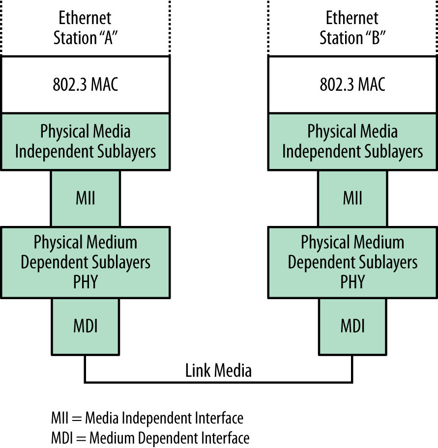
These sublayers are used for specifying the operations of the signaling and other mechanisms used to make the Ethernet link function for the given media speed being standardized. The sublayers help divide the task of sending signals over the physical media into further sections, some of which are independent of the media system and some of which depend on the specific medium involved.
The standard defines medium dependent interfaces (MDIs) for connections to each media system, and notes that all stations must rigidly adhere to the specifications for the physical media signals carried over the MDIs that are defined in the clauses of the standard that describe each Ethernet media system. The components used to couple signals directly onto the media are part of the physical medium dependent sublayers, also called the “PHY” (pronounced “fie”).
As the Ethernet system has evolved, it has developed a set of media independent interfaces (MIIs) for each media speed. This means that this portion of the Ethernet interface is not specific to a cabling system. These interfaces are one of the ways the standard provides for a given Ethernet interface to be connected to different types of cabling.
For example, an Ethernet switch port (interface) could be equipped with a transceiver connecting it to a twisted-pair link or a different transceiver connecting it to a fiber optic link. Both transceivers are MDIs that connect to the same switch port (but not at the same time). The switch port electronics contain the MII, which interfaces to multiple MDIs. With this, transceivers for multiple media systems can be developed without requiring changes in the Ethernet interface electronics in the switch port.
Media Independent Interfaces
The first media interface developed for the 10 Mb/s Ethernet system was called the “transceiver cable” in the DIX standard, but its name was later changed to attachment unit interface (AUI) in the IEEE standard. The AUI supports the 10 Mb/s media systems only, connecting to all media types: coaxial cable, twisted-pair, and optical fiber.
The next media attachment standard was developed as part of the Fast Ethernet standard, and this was the first time the IEEE standard used the term “media independent interface.” The 100 Mb/s MII provides support for both 10 and 100 Mb/s media segments. Both the AUI and MII standards included provisions for an external medium attachment unit (MAU), also known as a transceiver. The external MAU was connected between the cabling system and the Ethernet interface.
Tip
With the development of twisted-pair Ethernet that connects directly to RJ45 ports on Ethernet switches and other devices, external MAUs, or transceivers, connected to interfaces with external AUI cables (also called transceiver cables) are no longer used for Ethernet over copper cabling. A description of the older 10 and 100 Mb/s external transceivers can be found in Appendix C.
Next in the evolution of Ethernet, a gigabit media independent interface (GMII) was developed as part of the Gigabit Ethernet system. The GMII accommodates the increased speed of the Gigabit Ethernet system by providing an electrical definition for signals with a wider data path to the Ethernet interface, allowing them to carry more information as required by the faster speed. This set of signal paths is internal to the Ethernet interface and is not exposed to the user.
The MII data path has since been expanded to accommodate ever-faster versions of Ethernet, leading to multiple names for this element of the standard, which is now known as “xMII.” Table 7-1 shows a set of xMII names, taken from the various physical layer standards.
Ethernet PHY Components
As the standard has evolved, more xMII versions have been developed, and more elements have been defined in the physical layer to provide more options for internal interconnections and to make the signaling function over faster media systems. The Ethernet interface chips can now support a whole series of xMII signaling interfaces, which are brought into play depending on which speed of Ethernet is chosen. This enables the Ethernet interface to implement a range of physical layer elements, depending on the media speeds that the vendor chooses to support.
As shown in Figure 7-2, the physical layer includes a physical coding sublayer, which specifies the signal encoding required for a given speed of Ethernet. It also includes physical medium attachment and physical medium dependent standards, which vary depending on the media type (copper or fiber optic). Also included as needed can be a forward error correction element to make signaling work better at higher speeds, and Auto-Negotiation, which may be required on some media types, optional on other media types, or unused.
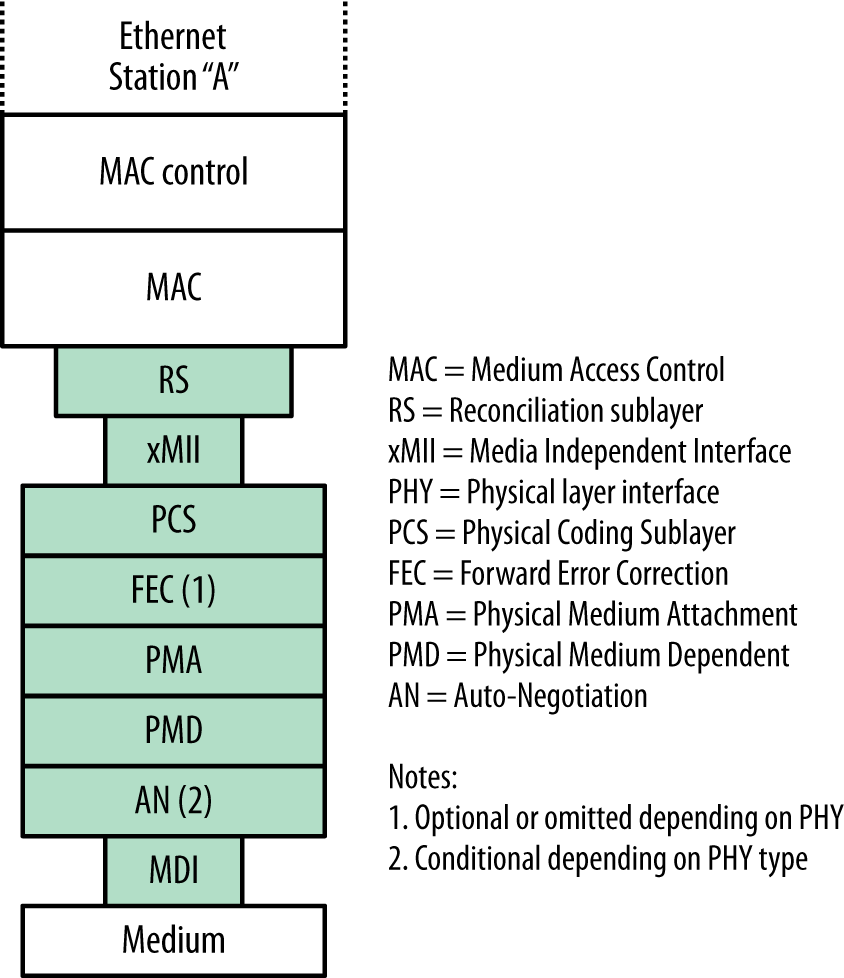
Also included in the set of specifications involved in putting Ethernet signals onto the medium is a reconciliation sublayer (RS), which is defined in the standard as a “mapping function that reconciles the signals at the Media Independent Interface (MII) to the Media Access Control (MAC)–Physical Signaling Sublayer (PLS) service definitions.”[24] In other words, the RS is a logical interface, provided to standardize the mapping for the signals carried between the MAC layer and the physical signaling layers.
These sublayers and other elements define the complex set of signaling standards that can coexist in a given Ethernet interface. For example, a modern 10 Gb/s Ethernet interface chip may support 100 Mb/s, 1 Gb/s, and 10 Gb/s operation over copper or fiber optic media systems. To do that, the chip is designed to provide multiple signaling systems over multiple internal signal paths, any of which can be configured internally in the chip to end up at the physical attachment to the medium.
This complexity is hidden from the user; all that you see is the eight-pin RJ45 copper port on a switch or computer, or a fiber optic transceiver that either is built in or that you insert into the Ethernet port on a switch or computer, depending on what the vendor chooses to provide in the way of options. The various signal encoding systems and logical interfaces are inside the port and are part of the Ethernet interface chipset. Which of the supported media systems and speeds is used at any given time may be chosen automatically by Auto-Negotiation, or configured manually by you in interaction with the interface management software on the switch or computer that you are connecting to the Ethernet.
Ethernet Signal Encoding
Signal encoding is a means of combining both clocking and data information into a self-synchronizing stream of signals sent over a media system. Each media system presents a certain challenge to the standards engineers in terms of sending Ethernet signals that can make it from one end of the cable to another.
As higher-speed Ethernet systems have evolved, more complex block encoding schemes have been developed. All of these signaling systems have the same set of goals. First, they must include sufficient clocking information along with the signals to ensure that the signal decoding circuitry can function correctly. Other goals include ensuring that the error rate is kept very low, and that the Ethernet frame data has a very high probability of surviving its trip over the media system.
Baseband Signaling Issues
The baseband signaling used in Ethernet media systems puts the bits of the Ethernet frame onto the link as a sequence of pulses or data symbols. These signals are reduced in amplitude and distorted by the electrical or photonic effects of being carried over the cable by the time they reach the other end of the link. The receiver’s job is to correctly detect each signal pulse as it arrives and to decode the correct bit value before transferring the information to the receiving MAC.
Electrical and digital filters and pulse-shaping circuits are used to restore the size and shape of the received waveforms; other measures are also taken to ensure that the received signals are sampled at the correct time in the pulse period and at the same rate as the transmitting clock. Because the transmitting and receiving clocks are on separate devices, synchronizing the clocks is accomplished by sending clocking information with the data. The receiving device synchronizes to the incoming data stream using clocking information encoded in the data, which makes it possible to correctly decode the received data. Clock recovery requires sufficient signal level transitions in the incoming signals to make it possible for the receiving device to correctly identify symbol boundaries.
The earliest encoding scheme was Manchester encoding, used to transmit 10 Mb/s signals. Manchester encoding provides a signal transition in the middle of each bit symbol, which is used by the receiver as clocking information to enable it to stay synchronized with the incoming signals and to correctly decode the ones and zeros being sent.
The Manchester encoding system is inefficient, however, requiring two transitions to represent each bit in a string of all ones or zeros, and this presents difficulties for signaling over copper cables at higher speeds. This led to the adoption of more complex signal encoding schemes for higher-speed Ethernet systems over copper cabling that could transmit a given bit rate with fewer signal transitions than Manchester would require. On the other hand, most of the fiber optic media systems use simple encoding schemes, because fiber optic cables can sustain higher-frequency signaling than copper media and are not susceptible to electrical effects like baseline wander.
Baseline Wander and Signal Encoding
Baseline wander is an issue that arises when sending and receiving higher-speed electrical signals over copper cabling. The signal-receiving circuits may lose synchronization if the data being sent remains constant and provides no transitions to detect (e.g., during long strings of zeros). More complex encoding schemes make it possible to manage this effect.
Baseline wander occurs because the copper Ethernet media systems are electrically coupled with transformers to the receiving electronics to maintain electrical isolation. This provides a measure of safety in case the copper cabling should accidentally have a high voltage placed on it due to an electrical fault in the cabling system.
However, transformer coupling also allows the average signal level to vary, and if, for example, a long series of zeros containing no signal transitions is sent, the signal level can drop below the voltage threshold used to detect a one or a zero, causing an erroneous value to be detected. To avoid this issue, faster Ethernet systems adopted a variety of techniques to improve signal transmission and recovery.
Advanced Signaling Techniques
To help avoid signal errors, higher-speed Ethernet systems employ a variety of techniques. These include:
- Data scrambling
- The bits in each byte are scrambled in an orderly and recoverable fashion, to ensure that there are no long series of zeros or ones being transmitted, increasing “transition density.” This avoids baseline wander and makes it easier to detect the clocking information in the stream of symbols being sent over the medium.
- Expanded code space
- More signaling codes are added in this approach to represent both data and control symbols, such as start of stream and end of stream signals. This helps improve frame detection and error detection.
- Forward error correcting codes
- This approach adds redundant information to the transmitted data, so that some types of transmission errors can be detected and corrected during frame transmission.
Continually increasing the speed of Ethernet has meant that cabling and connector technologies have also had to evolve to support the higher speeds. While the twisted-pair system has standardized on the use of the eight-position (RJ45) socket and plug connectors, the signal-handling quality of the twisted-pair cabling and connectors has steadily improved to support the higher signaling speeds. The fiber optic system has also evolved faster cabling and a variety of different connector types used to connect an Ethernet interface to the cabling.
Ethernet Interface
In the earliest days of Ethernet, the network interface card (NIC) was a fairly large circuit board covered with chips connected together to implement the necessary functions. Nowadays, an Ethernet interface is typically contained in a single chip, or even a portion of a larger “system-on-chip,” that incorporates all of the required Ethernet functions, including the MAC protocol. Ethernet interface chips are designed to keep up with the full rate of the Ethernet media systems that they support.
However, the Ethernet interface is only one of an entire set of entities that must interact to make network services happen. Various elements have an effect on how many Ethernet frames a given Ethernet switch or desktop or server computer can send and receive within a specified period of time. These include the speed with which the switch or computer system can respond to signals from the Ethernet interface chip, the amount of available port buffer memory for storing frames, and the efficiency of the interface driver software.
This is an important point to understand. All Ethernet interface chips are capable of sending and receiving a frame at the full frame rate for the media systems that they support. However, the total performance of the system is affected by the power of the computer’s CPU, the speed of internal signaling pathways linking the CPU with the Ethernet interface, the amount of buffer memory, and the quality of the software that interacts with the Ethernet interface. None of these elements are specified in the Ethernet standard.
If the computer system is not fast enough, then Ethernet frames may not be acknowledged or received. When that happens, the frames are dropped or ignored by the Ethernet interface. This is acceptable behavior as far as the standard is concerned, because no attempt is made to standardize computer performance.
These days, most computers are capable of sending and receiving a constant stream of Ethernet frames at the maximum frame rate of a 10 Mb/s, 100 Mb/s, or 1 Gb/s Ethernet system. However, slower computers, such as embedded servers with low-power CPUs and slow internal communication paths, may not be able to keep up with the full frame rate on the Ethernet systems to which they are attached.
Higher-Speed Ethernet Interfaces
It’s possible for a computer system to use a significant percentage of its CPU power to receive or transmit the full frame rate on high-speed Ethernet systems. You should be aware of these performance issues, and not assume that a given system can be connected to high-performance Ethernet links without issues.
If a machine that is working hard to keep up with a 1 Gb/s Ethernet channel is connected to a 10 Gb/s Ethernet, it will not suddenly be able to go 10 times faster—10 Gb/s Ethernet speeds and frame rates push the limits of even high-performance computer systems. As of this writing, a number of the desktop and server computers currently on the market cannot keep up with the full frame rate of a 10 Gb/s Ethernet channel.
While the signal paths inside high-performance servers may have enough bandwidth to keep up with a 10 Gb/s Ethernet channel, the network interface may still require the use of special software to help speed up processing of network protocol software, and to improve data rates between the server’s CPU and the 10 Gb/s Ethernet interface. Some vendors supply interfaces that provide high-level protocol packet processing onboard, to speed the flow of packets between the computer and the network. Other approaches include more sophisticated interface drivers capable of buffering several packets before interrupting the computer’s CPU. Yet another approach is the use of direct memory access techniques to manage packet flow in and out of the interface.
Next we’ll look at how the media signaling can be modified to reduce energy requirements.
Energy Efficient Ethernet
Now that we’ve seen how the media signaling components are organized and work together to send Ethernet signals from one station to another, this is a good place to describe how Energy Efficient Ethernet (EEE, pronounced “triple E”) can modify those signals to save power. EEE is an optional standard that currently applies to twisted-pair Ethernet media systems and also to the Ethernet standards used for sending signals over backplanes in devices such as chassis switches. Future extensions to the standard are expected to include more media systems.
One way to describe EEE is to compare it with the operational modes in standard and hybrid cars. When a hybrid car stops at an intersection, the gasoline engine is shut off to save power, and it is restarted when you press on the accelerator. Prior to the EEE standard, all Ethernet ports operated like standard cars with an engine that continued to run even when the car was stopped. The EEE standard makes it possible for ports to operate more like hybrid cars, and automatically shuts off some interface functions, minimizing the power needed to operate an Ethernet port until there is data to send.
Researchers at the University of South Florida initially raised the issue of saving power on Ethernet links, with a proposal called Adaptive Link Rate.[25] The researchers noted that hundreds of millions of Ethernet links were operating at full signaling speeds 100% of the time and consuming electrical power to do so, even though the signaling was only being used to send IDLE symbols much of the time.
The researchers found that many Ethernet links were operating at relatively low utilization rates, and that there were significant periods of time when no user data was being sent. For example, many desktop computers are not used after the working day ends, yet they continue to send Ethernet signals at full speed over the link all night long, just to indicate that the link is idle.
The researchers cited a 2002 study that found commercial office and telecommunications equipment to account for about 2.7% of U.S. electricity consumption in 2000. That study found that the networking equipment alone in nonresidential U.S. office spaces—not including PCs, monitors, servers, and the like—consumed 6.4 trillion watt hours in 2000.
The researchers noted that varying the signaling rate on an Ethernet link from 1 Gb/s to 100 Mb/s made a difference of about 4 watts of power consumption per port. They calculated that if the estimated 160 million Ethernet-connected PCs in the United States could operate their links at lower power levels when idle, the decreased power consumption could save $240 million a year.
Estimates published by Broadcom indicate that powering down networking ports when there is no data to send could reduce the energy required by the physical layer operations by up to 70% or more, making it possible to achieve overall savings of over 33% in the power required to operate an Ethernet switch.
IEEE EEE Standard
In response to these concerns, Energy Efficient Ethernet was developed over a period of several years and specified in the 802.3az supplement to the standard. The 802.3az supplement was approved as a standard on September 30, 2010, and was adopted as Clause 78 of the 2012 edition of the 802.3 standard. EEE provides a low power idle (LPI) mode of operation for media systems that use block encoded symbols. The standard also provides a lower-power version of the simpler 10 Mb/s Manchester encoded signaling.
The EEE system uses Auto-Negotiation to advertise EEE capabilities between link partners to determine whether EEE is supported, and to select the best set of parameters supported by both devices. When LPI mode is enabled, the Ethernet devices at both ends of a link can save power by effectively shutting off their transmitter and receiver circuits during periods of low link utilization, or by using the lower-power version of Manchester signaling if operating at 10 Mb/s.
EEE signals are used to transition to a lower level of power consumption; this is accomplished without changing the link status and without dropping or corrupting frames. The transition time into and out of low power consumption mode is designed to be small enough to be ignored by upper-layer protocols and applications. The goal was to avoid causing any noticeable delays when the EEE system is operating.
EEE media systems
EEE is currently supported over 100BASE-T, 1000BASE-T, and 10GBASE-T twisted-pair media systems. For operation over electrical backplanes, EEE also supports the 1000BASE-KX, 10GBASE-KX4, and 10GBASE-KR backplane media standards. The EEE standard also defines a reduced-power version of the 10 Mb/s signaling, called 10BASE-Te. The 10BASE-Te system fully interoperates with existing 10BASE-T transceivers over 100 meters of class D (Category 5) cabling, to provide a reduction in power consumption for systems operating at 10Mb/s. The 10BASE-T system does not use block encoding so it cannot support the EEE protocol.
Efforts to extend EEE capability into other media standards are underway, with work proceeding in the 40 and 100 Gb/s standards for backplanes and copper cabling. Efforts are also being made to extend EEE capability to fiber optic media systems.[26]
EEE Operation
EEE saves power by switching off functions in the Ethernet interface when no data needs to be transmitted or received. The decision as to whether the link should enter or exit low power idle mode is made by the interface software, based on whether or not there is Ethernet frame data that needs to be sent.
EEE operates over a link between two stations, and only for stations that are in the full-duplex mode of operation. Both stations must support EEE, or LPI mode cannot be enabled. When the stations first come up over the link, they use Auto-Negotiation to advertise their EEE capabilities.
Once the link partners have determined that they both support EEE, then the stations can use LPI signaling to indicate that there is a break in the data being sent, and that the link can go quiet until there is data to send. The EEE protocol uses a signal that is a modification of the normal IDLE symbol that is transmitted between frames on systems with complex encoding.
Figure 7-3 shows the LPI signals that are sent and received by the PHY. When the controller software determines that there is no data to send and that it can enter LPI mode, an LPI TX Request is sent. Following reception of the request, the PHY transmits LPI symbols for a defined period (Ts = time to sleep), the transmitter stops signaling, and the link enters LPI mode. This is the behavior for most of the supported media types.
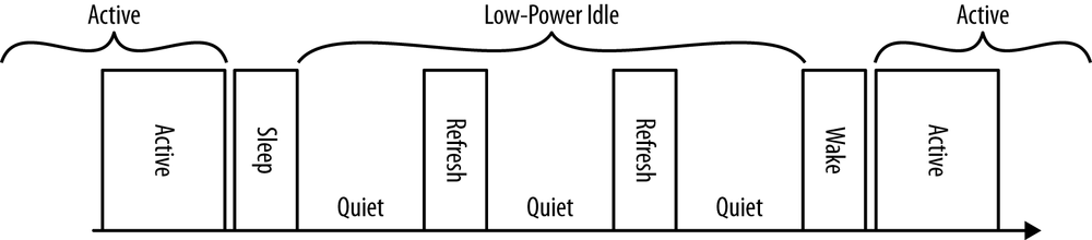
However, in the 1000BASE-T system, which uses a master-slave method for synchronizing signals sent over the link, the PHY operation for initiating LPI mode is symmetric. Only after the local 1000BASE-T PHY both transmits sleep symbols to and receives sleep symbols from the link partner does the PHY enter the quiet mode.
EEE states
While in quiet mode, the local PHY periodically transmits refresh signals. The refresh pulse that is periodically sent while the link is in LPI mode serves the same purpose as the link pulse in the 10BASE-T media system, and maintains link state. The frequency of the refresh symbols, which are sent multiple times per second, also prevents any situation where one link partner is disconnected and another connected without causing a link fail event. This maintains compatibility with any mechanisms that depend on continuous connectivity and that need to know when a link is disconnected.
The refresh signals are also intended to provide enough signaling over the cable to update adaptive filters and timing circuits in order to maintain link signaling integrity. The specific timing between refresh signals and the type of signal used for refresh varies according to each media type, to ensure that the specific media signaling requirements are being met to maintain a stable link signal while idle (which also ensures that the link can rapidly return to full operation).
This “quiet/refresh” cycle continues until the controller software detects that there is data to send, at which point it sends a message to clear the LPI mode. In response, the transmitter begins sending normal IDLE symbols, and after a predetermined time called Tw (time to wake) the PHY enters the active state and resumes normal operation.
The EEE protocol allows a link to be reawakened at any time, and there is no minimum or maximum sleep interval. The default wake time for each type of media system (PHY) is designed to be similar to the time taken to transmit a maximum-length frame. For example, the worst-case wake time for 1000BASE-T is 16.5 µs (16.5 millionths of a second), which is roughly the same time it takes to transmit a 2000-byte Ethernet frame over that media system. The wake time is defined in the standard as Tw_phy, and the maximum time to reawaken a link is defined as Tw_sys_tx, or “the longest period of time the system has to wait between a request to transmit and its readiness to transmit.”
Table 7-2 lists the wake times and maximum times to reawaken for some common media types. For two of the three media systems shown, the wake time and max time to reawaken are the same. The wake time on the 100BASE-TX system is 20.5 µs, and the maximum time to reawaken a 100BASE-TX link is 30 µs.
Managing EEE
While the EEE standard defines how low power idle mode is communicated between stations on a link and how the PHYs can transition into and out of this mode, it does not define when LPI mode can be used. The determination of when to enter LPI mode is left up to the system. Each system is expected to determine the policy for when to enter LPI mode. The policies used may include:
- Simplest policy
- When the transmit buffer is empty, wait a short time and then request LPI mode. When a frame arrives to send, reawaken the link.
- Buffer and burst policy
- When the transmit buffer is empty, request LPI mode. When one or more frames arrive for transmission, wait until a large enough set of frames arrives or until a timer expires, and then reawaken the link.
- Application-aware policy
- Monitor the transport or higher-layer communication software to understand when the link can be deactivated, or whether more packets should be expected soon.
Early EEE systems may support only the simplest policy. As vendors gain more experience with the system, it is expected that more complex policies will be developed. One area of interest is the power required for data center operations, and the development of energy management systems for centers with thousands of servers and network ports that could use EEE to realize energy savings across the set of data center ports.
EEE negotiation
The EEE protocol also provides a method for link partners to exchange LLDP packets, defined in IEEE 802.1AB, to negotiate wake times that are different than the defaults in the standard. The LLDP standard is already widely supported in networking equipment, making it possible to add wake timing negotiation without requiring that the switch support a new protocol. The LLDP-based negotiation ability allows a vendor to program equipment like a PC to go into a deeper sleep with more components powered down, resulting in greater power savings.
However, a deeper sleep also requires a longer time to wake, hence the need to re-negotiate the wake timing. The wake timing can be negotiated separately for each direction over the link depending on the equipment at each end, so that wake times can be asymmetric.
Impact of EEE Operation on Latency
Latency is the time required for an Ethernet frame to transit the set of equipment between a sending computer and the receiving system. Latency includes the inevitable serialization delays caused by transmitting Ethernet frames one bit at a time over Ethernet links. It also includes any time consumed by moving the Ethernet frame into and out of switch port buffers and across switching backplanes and switch fabrics.[27] The general goal is to minimize latency, so as to avoid any impacts on delay-sensitive applications, such as voice or video, where excessive packet delays may reduce voice quality or cause issues for video images.
The EEE protocol was designed to minimize the delays that occur when entering and leaving idle mode. The default wake times are similar to the amount of time required for transmitting a maximum-sized frame on the media system in question. This design keeps the impact on applications to a minimum, as a similar delay is incurred during the normal store and forward packet switching functions in Ethernet switches, in which the entire frame is read into port buffer memory (store) before being sent out the port, one bit at a time (forward).
However, some applications can be extremely sensitive to any extra latency. Some high-performance computing systems can be sensitive to the delay times experienced by interprocessor communications or synchronization traffic carried over Ethernet channels. Some financial trading applications also make strenuous attempts to minimize delay, using techniques such as cut-through switching to avoid spending any time on normal store and forward switching operations. These applications could be affected by the sleep and wake times incurred by EEE operation. In these cases, you may wish to disable EEE operation over the links involved.
Normal network traffic, including IP video, telephony, and telepresence, are designed to work over normal networks and typically have a built-in latency tolerance of anywhere from 1 to 10 milliseconds. This is quite a lot larger than the microseconds required for default EEE sleep and wake operations. Therefore, EEE operations using default times should have no impact on these applications.
EEE Power Savings
The EEE system makes it possible to achieve significant power savings, using an automatic system that causes links to dynamically enter and leave a low power idle mode depending on link traffic. The system is designed to operate invisibly, and does not require any user intervention to function. Now that Ethernet interface vendors are shipping interface chips that include EEE support, a link with EEE capability on both ends can automatically negotiate the use of EEE, saving power when there is no data to send.
EEE power savings in an interface
Intel has published a measurement of the power savings that can be realized using its 82579 Gigabit Ethernet interface chip, which supports 100 and 1000 Mb/s operation.[28] It shows the power consumed when the link is sending a frame, when sending normal IDLE symbols at full speed in the normal operating mode, and when in LPI mode.
Table 7-3 shows that EEE can reduce the power required to maintain idle operations on 1000BASE-T links by 91% when there are no frames to send, and by 74% on 100BASE-T links. While the actual amounts of power being saved are in the milliwatts, this adds up in a major way across thousands of ports at a given site and hundreds of millions of ports across the worldwide networks.
EEE power savings in a switch
Cisco Systems tested power consumption in one of its Catalyst 4500 switches with EEE enabled. The test consisted of connecting 384 ports to a stream of traffic being generated to simulate a bursty traffic pattern, of the kind typically seen being generated by desktop computers.[29]
The generated packet bursts were separated by 100 milliseconds, with 100,000 64-byte packets in each burst. Each port was connected to the adjacent port with a cable, such that traffic injected into port 1 was transmitted onto port 2, which was connected via cable from port 2 to port 3. Port 3 transmitted onto port 4, which was connected via cable to port 5, and so on. The goal was to see what kind of power savings EEE could achieve on 384 ports that were all carrying traffic that roughly simulates normal desktop user activity. Not counting the ports used to inject the packets and send the packet stream to the test equipment, there were a total of 191 EEE-enabled links connecting the ports together.
The power consumed by the switch was measured before and after enabling EEE. Prior to enabling EEE, the switch consumed 892 watts while running the packet test through all ports. After enabling EEE, the power consumption dropped to 751 watts total. The power reduction of 141 watts resulted in an average power saving per link of 0.74 watts when EEE was active. This test achieved roughly a 15% reduction in power consumed on 191 links, showing that EEE can achieve significant power savings even with continuous bursts of activity on all ports.
[24] IEEE Std 802.3-2012, paragraph 1.4.341, p. 38.
[25] C. Gunaratne and K. Christensen, “Ethernet Adaptive Link Rate: System Design and Performance Evaluation,” Proceedings 2006 31st IEEE Conference on Local Computer Networks (Nov. 2006): 28–35.
[26] Wael William Diab, “The Power and Promise of Energy Efficient Ethernet (EEE): A State of the Union Address,” Ethernet Alliance Blog, January 11, 2013.
[27] A definition of data communications latency is provided in RFC 1242, and a method for measuring switch latency is provided in RFC 2544. The QLogic “Introduction to Ethernet Latency” white paper describes latency testing in detail.
[28] Jorden Rodgers (JordanR), “Energy Efficient Ethernet: Technology, Application and Why You Should Care,” Wired Ethernet, May 5, 2011.
[29] Cisco Systems, Inc. and Intel, “IEEE 802.3az Energy Efficient Ethernet: Build Greener Networks,” 2011.