
Chapter 17. Fiber Optic Cables and Connectors
Fiber optic Ethernet cabling systems are based on multimode and single-mode fiber optic cables and connectors. Depending on the speed of the Ethernet media system and the type of fiber optic transmitters used in the system, the behavior of fiber optic media can vary. This is especially true for the high-speed Ethernet fiber optic systems, which send extremely rapid signals over fiber optic cable.
A major advantage of fiber optic cable is that the use of light pulses instead of electrical currents provides complete electrical isolation for equipment located at each end of a fiber optic link. This isolation provides immunity from hazards such as lightning strikes, and from the effects that can be caused by different levels of electrical ground potentials found in separate buildings.
For safe and reliable operation of your Ethernet system, electrical isolation of the sort provided by a fiber optic segment is essential when Ethernet segments are installed between buildings. Fiber optic media is also useful in environments such as manufacturing floors, because fiber optic segments are unaffected by the high levels of electrical noise that can be generated by heavy motors, welders, or other kinds of manufacturing equipment.
Fiber Optic Cable
There are a variety of fiber optic cable types; which you use is determined by the distance and speed required. The smallest cables are fiber optic patch cords, which often contain just 2 fibers, but may contain 12 or 24 fibers as needed on the 40 and 100 Gb/s Ethernet systems. Patch cords can be based on either multimode or single-mode fiber, depending on your requirements, and can also be equipped with whatever fiber optic connector you need at each end of the cable. Companies that build fiber optic cables can create cables to meet your requirements, and ship them to you within a day or two after you place the order.
Fiber optic horizontal cables for service to a work area are sometimes installed as part of a structured cabling system. However, in the vast majority of structured cabling systems today, Category 5e or 6A twisted-pair horizontal cables are used to deliver Ethernet signals to desktops and other devices.
Fiber optic backbone cables, on the other hand, are widely used in structured cabling systems to provide links between switches in telecommunications spaces within a building. These backbone cables usually contain 12 or 24 fibers, but they can contain more fibers as required. For large backbone cable installations, fiber optic cable manufacturers can build backbone cables to order, depending on your needs.
The ANSI/TIA-568 structured cabling standards, as described in Chapter 15, provide specifications for installing both backbone and horizontal segment fiber optic cables in a building.
Warning
Ethernet single-mode fiber optic equipment and other network devices based on single-mode fiber use laser light sources. Sufficiently powerful laser light can damage the retina of your eye without causing any feeling of pain, because the retina doesn’t have any pain receptors.
Don’t ever assume that it is safe to look into the end of a fiber optic cable. While Ethernet interfaces are designed to avoid sending full-power laser optical signals on disconnected interfaces, it’s always possible that the fiber optic cable you are looking at is not connected to a device that throttles power.
Fiber optic Ethernet transceivers for use on multimode fiber are based on LED transmitters that emit a form of light that is not dangerous to the eye. However, you should treat all fiber optic cables with caution. Beware of looking directly into any fiber optic cable, and always observe safety precautions to protect your eyesight when working around fiber optic cable systems.
Fiber Optic Core Diameters
The thickness of the core optical fiber used in fiber optic cables is very small and is measured in millionths of a meter, called micrometers (µm), or microns. One type of multimode fiber optic cable that was popular in the past has a 62.5 µm fiber optic core and 125 µm outer cladding (62.5/125). Modern cabling systems are based on multimode cable with a 50 µm core and 125 µm cladding (50/125).
Single-mode fiber has a much smaller core with the same 125 µm thickness of outer cladding. Commercial single-mode fibers have core diameters that can vary from approximately 8–10 µm. They are collectively referred to as “10 micron fiber” in the standard. By way of comparison, a single sheet of copy paper has a thickness of roughly 100 µm.
Fiber Optic Modes
A fiber optic “mode” is a path that light can follow in traveling down a fiber. As the name implies, multimode cable has a larger core designed to support multiple modes, or paths, of light propagation.
When an incoherent light source such as an LED is coupled to multimode fiber, multiple paths of light from the LED are transmitted over the cable, as shown in Figure 17-1. An advantage of the larger core is easier coupling of the light source to the cable. A disadvantage is that the wider corridor for light transmission allows the multiple paths of LED light to bounce off the sides of the fiber.
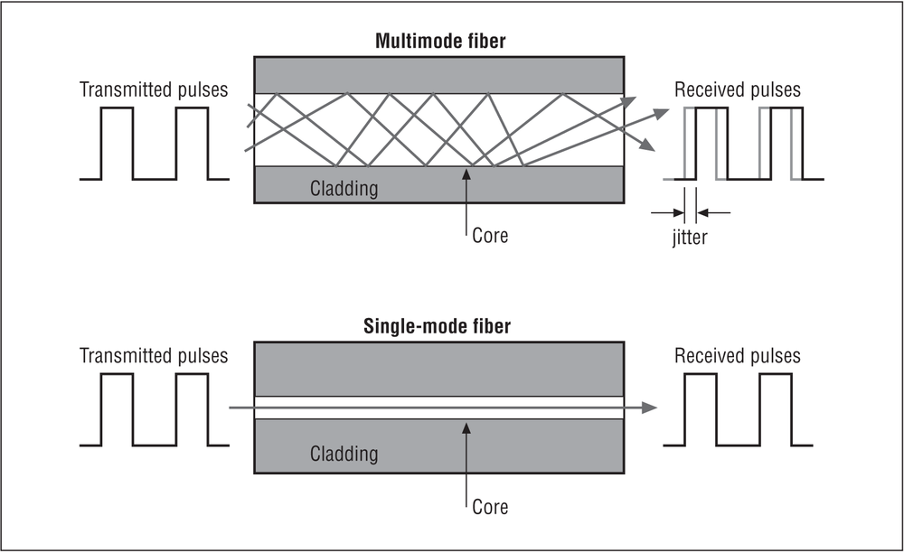
When this happens, these light paths arrive at the far end slightly out of phase, causing the light pulse to become dispersed, or spread out. This modal dispersion, or jitter, of the signal can cause problems with signal recovery at the far end. The longer the distance, the more signal dispersion there will be at a given signaling rate.
Single-mode fiber has a much smaller core, optimized to propagate a single mode, or path. When long-wavelength light (e.g., 1,300 nanometers) is injected into this fiber, only one mode will be active, and the rays of light will travel down the middle of the fiber. When a coherent light source from a laser is coupled to a single-mode fiber, the single beam of laser light is transmitted over the single mode of the cable.
With single-mode fiber, the signals don’t bounce against the cladding of the fiber, meaning there is no modal signal dispersion. Therefore, the light can travel a much longer distance without signal problems. The smaller core requires more precision to couple the light source to the cable, which is one reason why single-mode equipment is more expensive.
It is possible to couple a coherent laser light source to a multimode fiber. However, when this was first done for the Gigabit Ethernet media system, it was discovered that there can sometimes be a problem with signal propagation over the older cables that were common when Gigabit Ethernet was initally developed in 1999. This issue is called differential mode delay (DMD), and it is further described later in this chapter.
Since that time, newer versions of multimode cables have been developed that are designed to support laser light sources. In particular, these cables support the use of a less expensive laser technology called a Vertical Cavity Surface Emitting Laser (VCSEL). These lasers are well suited for low-cost transmission at the 850 nm wavelength, allowing for higher data rates over multimode fiber.
Fiber Optic Bandwidth
The distance over which an Ethernet signal will travel down a multimode fiber segment is primarily affected by signal strength and signal jitter, or dispersion. To help characterize the effects of dispersion, multimode fiber manufacturers specify their cables with a bandwidth rating, which is based on a figure of merit called the bandwidth-distance product, or simply bandwidth.
Tip
A figure of merit is a quantity used to characterize a component relative to its alternatives. Figures of merit are defined in engineering to provide a measure of a component’s utility for the intended task. Examples include CPU speed, contrast ratios for LCD displays, and fiber optic dispersion ratings.
The bandwidth for multimode fiber optic cable is specified as the product of megahertz times kilometers, shown as either MHz-km or MHz*km. Single-mode cable does not have the modal dispersion issues of multimode fiber, and therefore is not provided with a bandwidth rating.
A 200 MHz-km fiber can move 200 MHz of data up to one kilometer or 100 MHz of data as far as two kilometers. The amount of modal dispersion is different at different frequencies of light; therefore, the bandwidth rating depends on the frequency of light being sent over the cable. When using this spec, you need to know both the bandwidth rating and the frequency of light for which it applies on a given cable.
There is no way to field-test a fiber optic cable to derive a bandwidth-distance product. Instead, the bandwidth ratings can be found in vendor spec sheets (assuming you know the vendor and part number of the fiber cable). Multimode fiber optic media is manufactured in a range of bandwidths. A common rating for the older 62.5/125 µm cable was 160 MHz-km modal bandwidth at a wavelength of 850 nm. Newer versions of multimode fiber optic cables have since been developed with better ratings. To help keep things straight, the versions of multimode fiber have been provided with a rating system in the ISO/IEC 11801 standard based on the letters “OM,” which stand for “optical multimode.”
Table 17-1 shows the OM ratings for multimode fiber, showing the minimum modal bandwidth for two frequencies of operation.
| Fiber core diameter | ISO rating | MHz-km at 850 nm | MHz-km at 1,300 nm |
62.5 µm MMF | OM1 | 200 | 500 |
50 µm MMF | OM2 | 500 | 500 |
50 µm MMF | OM3 | 1,500 | 500 |
50 µm MMF | OM4 | 3,500 | 500 |
Fiber manufacturers have improved the design and manufacturing of their cables since the older OM1 and OM2 cables were sold, including the development of laser-optimized multimode fiber (LOMF). The lower-cost light emitting diodes (LEDs) used in older OM1/OM2 fiber optic media systems for Ethernet have a maximum signaling rate of roughly 600 Mb/s. The VCSELs that are used to transmit signals over LOMF are capable of signaling at rates of over 10 Gb/s, which makes them ideal for use in high-speed networks.
Fiber Optic Loss Budget
The optical power losses on a fiber optic link must be small enough to allow the signal to be received accurately. The link power loss budget is the total optical power loss allocated for all fiber cables and patch cords and associated connectors on the segment, as well as all of the power penalties allocated in the standard to account for dynamic signal impairment factors. The power loss caused by the cable and connectors alone is called either static power loss or channel insertion loss.
The power penalties allocated for dynamic signal impairment cannot be measured in the field with static power loss testers. Instead, the dynamic power penalties are allocated in the standard to account for signaling issues such as modal noise, relative intensity noise, and intersymbol interference. The combined set of cable and connector losses and the power penalties allocated for signaling losses make up the total optical power budget for the link.
The static loss, or channel insertion loss, includes the entire set of cables, patch cords, and connectors in the link. Optical power loss for a given type of fiber optic cable is expressed in dB/km (decibels per kilometer) at a specified wavelength. The “km” portion is assumed, and you will often see fiber optic loss measurements expressed using only the “dB” portion.
The channel insertion loss for a given link segment can be measured in the field with fiber optic test instruments that can tell you exactly how much optical loss there may be over a given segment at a given wavelength of light. The more connectors you have, and the longer your fiber link cable is, the higher the channel insertion loss will be. If the connectors or fiber splices are poorly made, or if there is finger oil and/or dust on the connector ends, then there will be higher optical loss on the segment.
When working with fiber optic cables, it is very important to keep the ends of the cables extremely clean. In addition, dust caps should be provided for any unused connectors to avoid any accumulation of dust and oil on the fiber optic equipment and cables. Fiber optic cleaning devices are available for cleaning the ends of fiber optic jumpers, cables, and transceiver ports before installation.
Note that fiber optic loss meters may use LED light sources operating at a typical wavelength of 850 nm. There is an issue when using such testers for faster Ethernet types, because they could produce an attenuation reading that would cause an otherwise acceptable link to be rejected. The faster Ethernet links (1 Gb/s and up) use laser light, which propagates more efficiently than LED light in most cases. Therefore, a loss reading performed with an LED-based tester can report a higher loss value than a tester with a laser light source.
Estimating the static optical loss
One way to provide a rough estimate of optical loss is to measure the segment length. Segment length is one of the most important cabling parameters for Ethernet fiber optic links, and the cable length will often determine whether a link will function (assuming that the optical losses of patch cables and connectors on a given segment are not excessive). Lower-cost field testers are available that can measure the length of an Ethernet segment, to help qualify it.
If the total segment length is acceptable, and if the link connectors and splices are correctly installed, then the link will probably work OK. If you have the test gear, then measuring the optical loss at the correct wavelength with the correct test device is the best method for determining optical loss. But in the absence of the correct test gear, optical cable length can provide a useful estimate.
If the link length is within the correct limits, but there is a high bit error rate or some other problem with the link, then to troubleshoot the issue you need to carefully check the optical attenuation. To get the most accurate attenuation test results, you must use a laser light source that operates at the same wavelength as the Ethernet media type that you intend to use.
Fiber Optic Connectors
A variety of fiber optic connectors are used, depending on the cable type and the Ethernet media system. The most commonly used fiber optic connectors as of this writing are the SC and LC connectors. You will also find ST connectors used on some older Ethernet equipment, and in older fiber optic cabling systems.
The SC connector is used on a variety of Ethernet transceivers. When higher density is needed to allow more ports within a given space, then the more compact LC connector is a popular choice. The Ethernet systems that operate at 40 and 100 Gb/s require multiple strands of fiber for their short reach media segments. The multiple-strand fiber cables, also known as “ribbon trunks,” are terminated in multifiber push-on (MPO) connectors. An MPO connector can provide 12 or 24 fibers, depending on whether you are connecting to a 40 or 100 Gb/s short reach Ethernet interface.
ST Connectors
The ST (“straight tip”) fiber optic connector is a registered trademark of AT&T Corp., formerly known as the American Telephone and Telegraph Company. The formal name of the ST connector in the ISO/IEC international standards is BFOC/2.5. ST connectors were once a popular choice for cabling system termination panels.
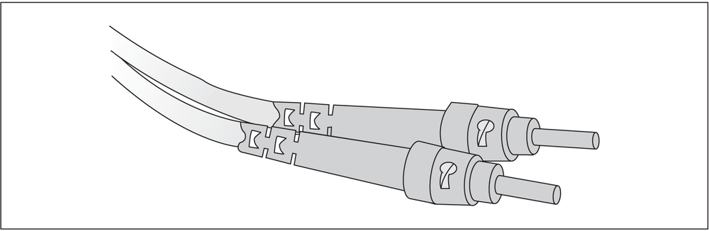
Figure 17-2 shows a pair of fiber optic cables equipped with ST plug connectors. The ST connector is a spring-loaded bayonet connector whose outer ring locks onto the connection. The ST connector has a key on an inner sleeve along with the outer bayonet ring.
To make a connection, you line up the key on the inner sleeve of the ST plug with a corresponding slot on the ST receptacle. Then you push the connector in and lock it in place by twisting the outer bayonet ring. This provides a tight connection with precise alignment between the two pieces of fiber optic cable being joined. The ST connector provides a very reliable connection that does not easily loosen or pop out of place.
SC Connectors
SC, meaning “subscriber connector,” is a registered trademark of Nippon Telegraph and Telephone (NTT). The SC connector is widely used by vendors for Ethernet interfaces, including long-range interfaces for 10, 40, and 100 Gb/s Ethernet.
The duplex SC connector shown in Figure 17-3 is also a recommended connector in the 100BASE-FX and 1000BASE-X standards.
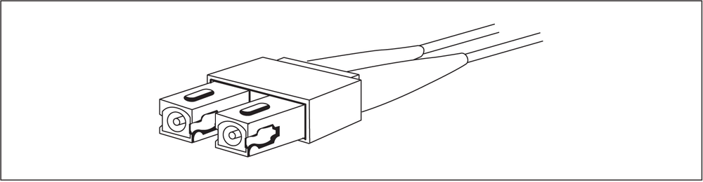
The SC connector is designed for ease of use; the connector is pushed into place and automatically snaps into the connector housing to complete the connection. Make sure to seat the connector firmly, pushing until it has “clicked” into place. An SC connector might still work if it is not installed tightly, but you will encounter high error rates and eventually the link may fail completely.
LC Connectors
The LC connector was developed by Lucent, hence the name (“Lucent connector”). An LC connector uses a retaining tab mechanism, similar to an RJ45 connector, while the connector body has a square shape similar to the SC connector but smaller in size. LC connectors are usually held together in a duplex configuration with a plastic clip, as shown in Figure 17-4. The ferrule of an LC connector is 1.25 mm.
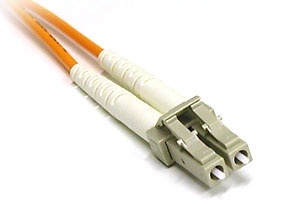
The LC connector provides two fiber optic connections in a smaller space. Because the LC connector takes up about half the space required by an SC connector, this allows vendors to provide more ports on a switch front panel or chassis module.
MPO Connectors
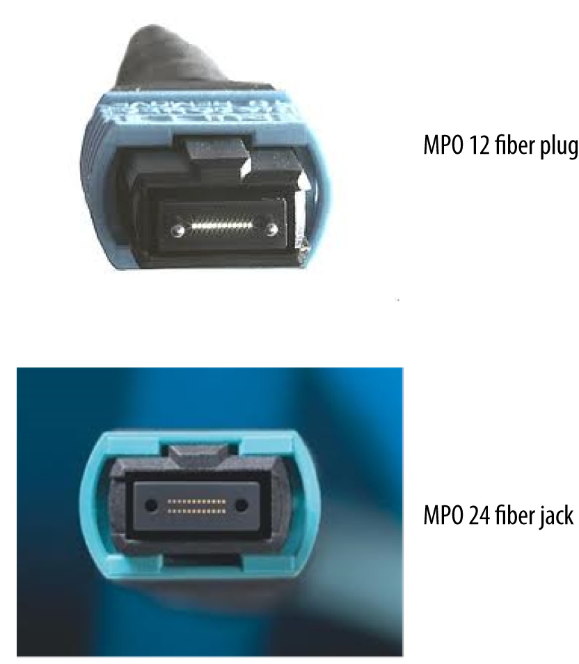
As its name implies, the multifiber push-on (MPO) connector provides multiple fibers in a connector that is both “push to connect” and “push to disconnect.” This connector is defined by IEC-61754-7, “Fibre optic interconnecting devices and passive components,” and TIA-604-5-D, “Fiber Optic Connector Intermateability Standard, Type MPO.” Both standards specify 12- and 24-fiber versions of the MPO connector.
You will also see the term MTP used for this connector type, which is a registered trademark of US Conec for a connector that is compliant with the MPO standards (meaning that the MTP connector is an MPO connector). However, the MTP connector has been enhanced by US Conec to provide several product features, including the ability to change gender or to repolish in the field, a floating ferrule for improved optical performance, and elliptical guide pins to provide for tighter tolerance in alignment. Some of these features are covered under patents.
Figure 17-5 shows two MPO connectors. One is a 12-fiber MPO plug, with the alignment pins sticking out. The other is a 24-fiber MPO jack, with alignment holes that mate with the alignment pins.
Building Fiber Optic Cables
Fiber optic patch cables can readily be purchased with fiber optic connectors already installed, allowing you to make relatively short-distance fiber connections quite easily. However, many fiber optic systems are installed to cover long distances between buildings or as backbone systems inside buildings. In this case, the typical installation is based on raw fiber, which is pulled into place and then terminated with fiber connectors that are installed in fiber optic patch panels. Long fiber optic segments may require the installation of several fiber optic cable segments, which are spliced together into a continuous cable.
There are a variety of fiber optic cable types and sizes, designed to meet virtually any installation requirement. While it’s not rocket science, terminating a fiber optic cable in a connector and splicing raw fiber ends together requires specialized equipment and skills.
During installation, there are a number of special techniques that may be used for fiber optic cable splicing and terminating. Testing and verifying the operation of fiber optic cables also requires special equipment and training on how to operate the equipment. That’s why the vast majority of sites turn to certified fiber optic installers and cable contractors for fiber optic installation and testing on segments that require cable termination and splicing.
Fiber Optic Color Codes
According to the TIA standard, unless the color coding is used for some other purpose, the connector plug body should be identified by the following colors where possible:
- Multimode: beige
- Single-mode: blue
- Angle Polished Contact (APC) single-mode connectors: green
The strain relief on the cable end and the cable jacket are also identified by a color code, as outlined in Table 17-2.
| Fiber type and class | Diameter | Jacket color |
Multimode OM1/OM2 | 62.5/125 µm | Orange |
Multimode OM2 | 50/125 µm | Orange |
Laser-optimized Multimode OM3/OM4 | 50/125 µm | Aqua |
Single-mode | 10/125 µm | Yellow |
Multifiber cables, also known as ribbon cables, have a color code for each of the fiber optic strands in the cable. As shown in Table 17-3, solid colors are used on the first 12 strands. If the ribbon cable has more than 12 strands, then the next 12 strands will have a solid color base and a “tracer” color, which is a second color that is marked with a dashed or continuous line, a dashed or spiral line, ring stripes, or hash marks.
| Position number | Color | Position number | Color and tracer |
1 | Blue | 13 | Blue with black tracer |
2 | Orange | 14 | Orange with black tracer |
3 | Green | 15 | Green with black tracer |
4 | Brown | 16 | Brown with black tracer |
5 | Slate | 17 | Slate with black tracer |
6 | White | 18 | White with black tracer |
7 | Red | 19 | Red with black tracer |
8 | Black | 20 | Black with yellow tracer |
9 | Yellow | 21 | Yellow with black tracer |
10 | Violet | 22 | Violet with black tracer |
11 | Rose | 23 | Rose with black tracer |
12 | Aqua | 24 | Aqua with black tracer |
Signal Crossover in Fiber Optic Systems
A signal crossover is required to make a connection between an Ethernet transceiver attached to a station and the transceiver located in an Ethernet port. To make the data flow properly, the transmit data output of one transceiver must end up at the receive data input of the other transceiver. When connecting two nearby devices with a fiber optic patch cable, you must ensure that the transmit data pins at one device are connected to the receive data pins at the other device, and vice versa.
In the twisted-pair Ethernet system, signal crossover is done inside the Ethernet switch port using the Auto-MDIX system (as described in Chapter 16), and the structured cabling standard recommends wiring the twisted-pair cable segment straight through. Unlike with twisted-pair Ethernet, the structured cabling standard recommends that signal crossover for fiber optic horizontal segments be done in the cabling segment, and not at the Ethernet device.
For horizontal fiber optic segments installed as part of a structured cabling system, the connectors on the fiber optic cable should be oriented to achieve the crossover. For example, fiber optic cables are usually terminated in a set of fiber optic connectors located at the work area and the wiring closet. For a fiber optic cable with two optical fibers in it, fiber #1 is connected to the A connector at the work area end of the segment and the B connector at the wiring closet end. Fiber #2 is connected to the B connector at the work area, and the A connector at the wiring closet.
Using this method, the user or the network technician can connect fiber optic Ethernet ports to the fiber optic connectors on the horizontal cabling segment using straight-through fiber optic patch cables. They need not concern themselves about the signal crossover, because it is already accomplished in the fiber optic horizontal segment.
On the other hand, backbone fiber optic cable systems that go between floors of a building, or between buildings on a campus, are usually wired straight through. When making a connection between an Ethernet switch port and a backbone fiber optic system, you need to make sure that the signal crossover is achieved in the patch cable at one end of the link.
Signal Crossover in MPO Cables
Ribbon cables terminated with MPO connectors present some challenges when it comes to maintaining the correct signal crossover in a segment consisting of multiple fiber optic strands. The ANSI/TIA-568-C.3 standard provides a set of “Guidelines for Maintaining Polarity Using Array Connectors” that describe three types of MPO-to-MPO array cables, defined as Types A, B, and C. These cables are used to provide three different methods for maintaining a crossover connection. Method A is the preferred method, and is based on Type A MPO cables.
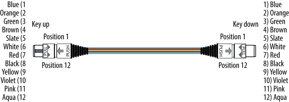
Figure 17-6 shows a Type A straight-through ribbon cable with 12 fibers terminated in MPO connectors. A Method A backbone link is cabled “straight through,” terminating in the cabling system patch panel. One end of the link will have a straight-through patch cable, connecting from the patch panel to the Ethernet interface. The other end of the link will have a crossover cable connecting to the Ethernet interface. The guidelines recommend keeping all of the crossover patch cables at one end of the link, to keep the system as simple as possible and help the installer to avoid connecting the wrong type of patch cable.
The guidelines also show Method B and Method C, which are two methods for providing a crossover path built into the MPO backbone cables themselves. Given the complexity of these approaches and the difficulty of implementing them correctly, they are both rarely used.
As you can see, there are a variety of approaches to managing the signal crossover for the 12-fiber and 24-fiber systems needed to support 40 and 100 Gb/s Ethernet. For the best results, make sure you know which method your site is using in the cabling system, and order the correct MPO cable types to make the connections and achieve the signal crossover. Note that some vendors provide special MPO connectors that make it possible to change connector gender and polarity (crossover) in the field, which could be a handy way to resolve MPO-to-MPO connectivity issues.[55]