CHAPTER 1
The BeagleBone Hardware
In this chapter, you are introduced to the BeagleBone platform hardware. The chapter focuses on the BeagleBone Black and the various subsystems and physical inputs/outputs of the board. In addition, the chapter lists accessories that can be very helpful in developing your own BeagleBone‐based projects. By the end of this chapter, you should have an appreciation of the power and complexity of this computing platform. You should also be aware of the first steps to take to protect your board from physical damage.
Introduction to the Platform
The BeagleBone is a compact, low‐cost, open‐source Linux computing platform that can be used to build complex applications that interface high‐level software and low‐level electronic circuits. It is an ideal platform for prototyping project and product designs that take advantage of the power and freedom of Linux, combined with direct access to input/output pins and buses, allowing you to interface with electronics components, modules, and USB devices. The characteristics of the BeagleBone platform are that it
- is powerful, as it contains a processor that can perform up to 2 billion instructions per second,
- is low‐cost, available for as little as $45–$55,
- supports many standard interfaces for electronics devices,
- uses little power, running at between 1 W (idle) and 2.3 W (peak),
- is expandable through the use of daughterboards and USB devices,
- is supported by a huge community of innovators and enthusiasts, and
- is open‐hardware and supports open‐software tools and applications.
The BeagleBone runs the Linux operating system, which means that you can use many open‐source software libraries and applications directly with it. Open‐source software driver availability also enables you to interface devices such as USB cameras, keyboards and Wi‐Fi adapters with your project, without having to source proprietary alternatives. Therefore, you have access to comprehensive libraries of code that have been built by a talented open‐source community; however, it is important to remember that the code typically comes without any type of warranty or guarantee. If there are problems, then you have to rely on the good nature of the community to resolve them. Of course, you could also fix the problems yourself and make the solutions publicly available.
The BeagleBone platform is formed by the integration of a high‐performance microprocessor on a printed circuit board (PCB) and an extensive software ecosystem. The physical PCB is not a complete product; rather it is a prototype reference design that you can use to build a complete product. It is an open‐hardware platform, meaning that you can download and use the BeagleBone hardware schematics and layout directly within your own product design. In fact, despite the impressive capability of the BeagleBone platform, it does not fully expose all of the features and interfaces of the Texas Instruments Sitara AM335x microprocessor.
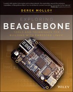
One impressive feature of the BeagleBone is that its functionality can be extended with daughterboards, called capes, that connect to the P8 and P9 headers (the two black 2×23 connector rows in Figure 1-1). You can design your own capes and attach them securely to your BeagleBone using these headers. In addition, many capes are available for purchase that can be used to expand the functionality of your BeagleBone platform. Some examples of these are described toward the end of this chapter.
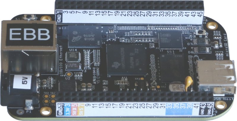
Figure 1-1 The BeagleBone Black computing platform (revision C board with printed pin labels)
The BeagleBone PCBs were designed by Gerald Coley, a co‐founder of the BeagleBoard.org Foundation. However, the boards, and several of its capes, are manufactured by CircuitCo (www.circuitco.com). The PCB layout for the BeagleBone Black was also created by CircuitCo. Recently, Element14 (www.element14.com) has begun manufacturing a BeagleBoard.org-compliant version of the BeagleBone Black. Therefore, when you purchase a BeagleBone board, you are not purchasing it from BeagleBoard.org; rather, BeagleBoard.org is the focal point for a community of developers and users.
Who Should Use the BeagleBone
Anybody who wishes to transform an engineering concept into a real interactive electronics product, project, prototype, or work of art should consider using the BeagleBone. That said, integrating high‐level software and low‐level electronics is not an easy task. However, the difficulty involved in an implementation depends on the level of sophistication that the project demands.
The BeagleBone community is working hard to ensure that the BeagleBone platform is accessible by everyone who is interested in integrating it into their projects, whether they are students, makers, artists, or hobbyists. Tools and software development environments, such as Jason Kridner’s BoneScript library (Kridner is a co‐founder of BeagleBoard.org and a technical editor of this book) and the Cloud9 integrated development environment (IDE), enable users to write and build code directly in a web browser that is capable of controlling electronics hardware. BoneScript is introduced in Chapter 2. Developments like Blockly (code.google.com/p/blockly) and Snap (snap.berkeley.edu) have the potential to be integrated with BoneScript to further improve accessibility for new users.
For more advanced users, with electronics or computing knowledge, the BeagleBone platform enables additional development and customization to meet specific project needs. Again, such customization is not trivial: You may be an electronics expert, but high‐level software programming and/or the Linux operating system might cause you difficulty. Or, you may be a programming guru but you have never wired an LED! This book aims to cater to all types of users, providing each type of reader with enough Linux, electronics, and software exposure to ensure that you can be productive, regardless of your previous experience level.
When to Use the BeagleBone
The BeagleBone is perfectly placed for the integration of high‐level software and low‐level electronics in any type of project. Whether you are planning to build an automated home management system, robot, smart display, sensor network, vending machine, or Internet‐connected work of interactive art, the BeagleBone has the processing power to do whatever you can imagine of an embedded device.
The major advantage of the BeagleBone over more traditional embedded systems, such as the Arduino, PIC, and AVR microcontrollers, is apparent when you leverage the Linux OS for your projects. For example, if you built a home automation system using the BeagleBone and you then decided that you wanted to make certain information available on the Internet, you could simply install the Apache web server. You could then use server‐side scripting or your favorite programming language to interface with your home automation system in order to capture and share the information. Alternatively, your project might require secure remote shell access. In that case, you could install a secure shell (SSH) server, simply by using the Linux command sudo apt‐get install sshd (these commands are covered in Chapter 2). This could potentially save you weeks of development work. In addition, you have the comfort of knowing that the same software is running securely on millions of machines around the world.
Linux also provides you with device driver support for many USB peripherals and adapters, making it possible for you to connect cameras, Wi‐Fi adapters, and other low‐cost consumer peripherals directly to your platform, without the need for complex and/or expensive software driver development.
When You Should Not Use the BeagleBone
The Linux OS was not designed for real‐time or predictable processing. Its kernel is not preemptive, which means that once the processor begins executing kernel code it cannot be interrupted. This would be problematic if, for example, you wished to sample a sensor precisely every one millionth of a second. If the precise time arises to take a sample and the kernel is busy with a different task, then it cannot be interrupted. Therefore, in its default state, the BeagleBone is not an ideal platform for real‐time systems applications. Real‐time versions of Linux are available, but they are currently targeted at very experienced Linux developers. However, the BeagleBone does have an on‐board solution that goes some way toward resolving this problem. Within the BeagleBone’s AM335x, there are two on‐board microcontrollers, called Programmable Real‐time Units (PRUs), which can be programmed for real‐time interfacing applications. This is an advanced topic that is described in Chapter 13.
There are low‐cost dedicated solutions available for real‐time sampling and control tasks (such as the TI Stellaris ARM platform) that may be more appropriate. It is also important to remember that you can interconnect such real‐time microcontrollers to the BeagleBone via electrical buses (e.g., I2C, UART, CAN bus, and Ethernet) and have the BeagleBone act as the central processor for a distributed control system. This concept is described in Chapter 9 and Chapter 10.
The second application type that the BeagleBone platform will find difficult is that of playing high‐definition video. The processing overhead of software decoding and playing encoded video streams is immense, and is beyond the capability of the BeagleBone at high‐definition video resolutions. The Raspberry Pi (www.raspberrypi.org) board has this capability because its Broadcom BCM28351 processor was designed for multimedia applications, and it has a hardware implementation of H.264/MPG‐4 and MPG‐2/VC‐1 (via additional license) decoders and encoders. For applications such as running XMBC home media center (www.xbmc.org), you are better off purchasing a Raspberry Pi (Model B+), but for building advanced applications that interface to electronics, the BeagleBone is a clear choice.
BeagleBone Documentation
This book integrates my experiences in developing with the BeagleBone platform along with supporting background materials on embedded Linux, software development, and general electronics, to create an in‐depth guide to building with this platform. However, it is simply not possible to cover everything in just one book, so I have avoided restating information that is listed in the key documents and websites described in this section. The first starting point for supporting documentation is always the following:
-
The BeagleBoard.org website: This provides the main support for this platform, with software guides, community links, and downloads to support your development. An excellent “Getting Started” guide and blog is available at the website
www.beagleboard.org.A huge amount of documentation is available on the BeagleBone platform, but the most important documents are as follows:
- BeagleBone Black System Reference Manual (SRM): This is the core document that describes the BeagleBone Black hardware. Authored by Gerald Coley, it is a comprehensive document that is complex in parts, but it is important that you have a copy along with this book. It is a live document, approximately 125 pages, that is released with every new revision of the BeagleBone. It is available free from the BeagleBone “Getting Started” web page.
- Sitara AM335x Cortex‐A8 Technical Reference Manual (TRM): The key component of the BeagleBone is its Texas Instruments microprocessor, and this document contains anything you could possibly want to know about its internal workings. The AM335x is a complex device, and that is reflected in the length of the TRM—4,727 pages! If you need to understand something about the inner workings of the microprocessor or the device configuration on the BeagleBone, it is likely that the answer is contained in this document. I refer to tables in the TRM throughout this book so that hopefully you will become familiar with the language contained therein. This document is available free from
www.ti.com/product/am3358.
Key websites are also available to support your learning on this platform, with combinations of tutorials, discussion forums, sample code libraries, Linux distributions, and project ideas to stimulate your creative side. Here is a selection of important websites:
- The website for this book:
www.exploringbeaglebone.com - My personal blog site:
www.derekmolloy.ie - The eLinux.org website:
www.elinux.org - The eewiki:
www.eewiki.net - Hipstercircuits.com:
www.hipstercircuits.com - OZ9AEC:
www.oz9aec.net
Getting started with the BeagleBone platform software is described in Chapter 2. The remainder of this chapter discusses the BeagleBone PCB itself, explaining the functionality that is available, summarizing the SRM, and providing some examples of the types of peripherals and capes that you might like to connect to the BeagleBone.
The BeagleBone Hardware
At its heart, the BeagleBone Black uses the Texas Instruments Sitara AM335x Cortex A8 ARM microprocessor. While the BeagleBone Black is the focus of this book, multiple boards have been developed by BeagleBoard.org, including BeagleBoard, BeagleBoard XM, BeagleBone, BeagleBone Black, and the Arduino Tre (BeagleBoard and Arduino combined on a single board). The BeagleBone is discussed in detail in the next section, but here are some summary details on the different boards (in historical order):
- (2008) BeagleBoard ($125): The original open‐hardware ARM‐based development board that had HD video support. It has a 720 MHz ARM A8 processor but no on‐board Ethernet.
- (2010) BeagleBoard xM ($149): Similar to BeagleBoard, except with a 1 GHz ARM (AM37x) processor, 512 MB memory, four USB ports, and Ethernet support. Despite the low cost of the new BeagleBone boards, the BeagleBoard xM is very popular for its C64+TMDSP core for digital signal processing (DSP) applications.
- (2011) BeagleBone ($89): Smaller footprint than the BeagleBoard. It has a 720 MHz processor and 256 MB memory, Ethernet support, and low-level/output (e.g., analog to digital converters), but no on-board video support.
- (2013) BeagleBone Black ($45–$55): This board enhances the BeagleBone with a 1 GHz processor, 512 MB of DDR3 memory, Ethernet, eMMC storage, and HDMI video support.
The BeagleBone Black platform is the focus of this book, mainly due to its feature set and price point in comparison to the other offerings; however, most of the discussion in this book applies generally to all platforms.
BeagleBone Versions
As just mentioned, two versions of the BeagleBone are available: the older BeagleBone White (BBW), or just BeagleBone; and the newer BeagleBone Black (BBB). Both boards have a very small form factor, fitting neatly inside an Altoids mint tin, as shown in Figure 1-2(a). Traditionally, Altoids tins have been upcycled by engineers as a low‐cost housing for electronics projects. Given the complexity of the BeagleBone boards, it is impressive that they fit inside the tin—it also helps to explain the rounded corners on the BeagleBone boards! Holes can be formed in the case to provide access to the board connectors, but of course it is necessary to electrically insulate the aluminum tin before using it to house your board.
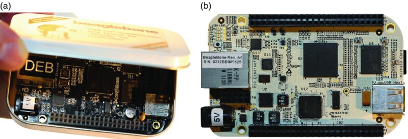
Figure 1-2 (a) The BeagleBone Black (BBB) in an Altoids tin box; (b) the BeagleBone White (BBW)
To achieve such a small form factor, the components are densely placed on the BeagleBone, and a six‐layer PCB is used to achieve interconnects. As an example, the AM335x (ZCZ) processors used on the BeagleBone platforms have a ball grid array of 324 pins, with a 0.80 mm ball pitch.
Table 1-1 lists the main differences between the BBB boards and the BBW boards. The first obvious difference is the price. Despite the improvement in specification, the BBB is just over half the price of the BBW, and is very competitively priced with other embedded Linux boards, such as the Raspberry Pi (Model B+).
Table 1-1 The BeagleBone Black (BBB) vs. the BeagleBone White (BBW)
| FEATURE | BEAGLEBONE BLACK (BBB) | BEAGLEBONE WHITE (BBW) |
| Price | About $45–$55 | About $89 |
| Processor | 1 GHz AM335x | 720 Mhz AM3359 |
| Memory | 512 MB DDR3 (faster 1.6 GB/s and lower power) | 256 MB DDR2 |
| Storage | On‐board 2 GB eMMC (4 GB eMMC on the Revision C board) and micro‐SD card slot | Micro‐SD card slot only |
| Video | On‐board HDMI | No on‐board HDMI. Optional cape available. |
| Debugging | JTAG header present but not populated | JTAG over USB available |
| Serial Connection | TTL header present but separate cable needed | Serial over USB |
| Input/Output Headers | Almost the same, but fewer GPIO pins might be available due to eMMC and HDMI functionality on the BBB | |
The manufacture cost of the BBB was reduced by removing certain functionality from the BBW, such as the USB serial connection, USB JTAG debug emulation, and a power expansion header. However, the step‐up in functionality to include on‐board eMMC storage, HDMI video output, twice the memory, and a faster processor for just over half the price means that the BBB represents particularly impressive value for the money. It is clear that the BBB has reached a price/performance sweet spot that has made it an exceptionally popular platform. The eLinux.org website maintains a record of board shipment numbers that currently indicates 13,000 boards are shipping per month from CircuitCo. Despite this fact, demand continues to outstrip supply, and recently new manufacturers have come on‐stream to help with meeting this demand.
The BeagleBone Black Hardware
Figure 1-3 and Figure 1-4 detail the core systems of the BBB. The first set of callouts, 1 to 8, identify and describe the key systems on the BBB. The microprocessor on the BBB is a Texas Instruments Sitara AM335x Cortex A8 ARM Microprocessor.2 It is a RISC (reduced instruction set computing) processor, so at 1,000 MHz the processor executes 2,000 million instructions per second (MIPS). The processor runs at about 1 W idle and 2.3 W for heavy processing loads.
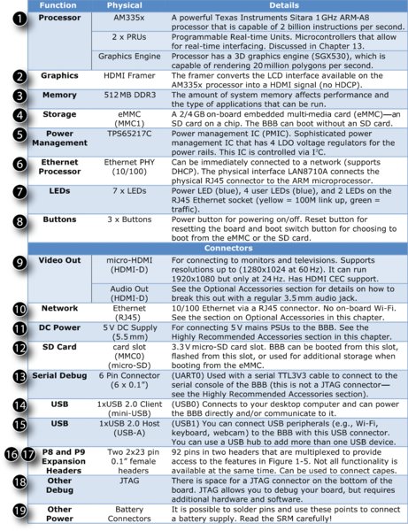
Figure 1-3 Table of BBB subsystems and connectors
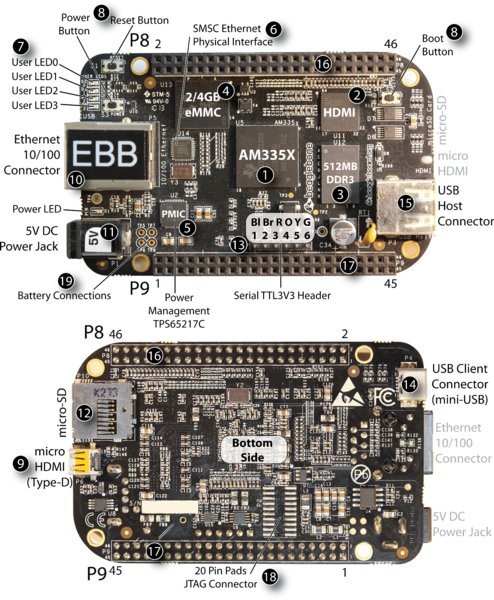
Figure 1-4 The BeagleBone Black (BBB) top and bottom views
The next set of callouts, 9 to 19, identifies the various connectors on the BBB, their physical characteristics, and their function. For connector 18, the JTAG connector, there are 20 pre‐tinned pads. You need to purchase a connector (such as Samtec FTR‐110‐03‐G‐D‐06) for this and carefully solder it to the board. In addition, you need a JTAG interface and associated debug software. The BBW has on‐board USB JTAG support.
If you would like these images for your own reference, Figures 1-3, 1-4, and 1-5 are available as a high‐resolution PDF poster prints at the chapter web page: www.exploringbeaglebone.com/chapter1/.
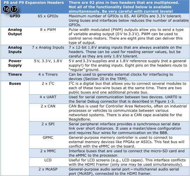
Figure 1-5 Table of functionality available on the P8 and P9 headers
Figure 1-5 details the various inputs and outputs that are available on the P8 and P9 headers. There are 92 pins in total on these headers (2×46); however, not all are available for general‐purpose input/outputs (GPIOs). Several of the connections have a fixed configuration:
- Eight pins are connected to “digital” ground.
- Nine pins are required for the analog inputs (seven inputs, ground, and 1.8 V reference voltage).
- Six pins are allocated to voltage supplies: 3.3 V (up to 250 mA), 5 V system (up to 250 mA) and 5 V VDD (up to 1 A if powered via DC Jack—power can be supplied to the board via the VDD_5 V pins).
- Two are allocated to one of the I2C buses.
- Two are allocated to the power and reset buttons.
The remaining 65 connectors are available to be multiplexed to many different functions, several of which are listed in Figure 1-5. The function of each of these input/output types is discussed in Chapter 6 and Chapter 8.
BeagleBone Accessories
The BBB board is packaged with a USB 2.0 cable (micro‐USB plug to USB A plug), which is used to connect the BBB (via the USB Client Connector) to a desktop computer. It does not come with a micro‐SD card, as the Linux installation is already present on the board’s eMMC. It will boot to Linux directly out of the box. The BBW is packaged with a micro‐SD card, as it has no on‐board eMMC.
Highly Recommended Accessories
The following accessories are recommended for purchase along with your BBB board. If you are planning to carry out development work with the BBB, then you should probably have all of them.
Micro‐SD Card (for Flashing the BBB)
A micro‐SD card enables you to write new Linux images to your BBB. If you accidently damage the Linux file system during your experimentation with the BBB, the micro‐SD card will enable you to restore your system. Ideally, you should have two dedicated SD cards, one for a boot image and one for a flasher image.
Purchase a micro‐SD card of at least 4 GB capacity. You may also require a micro‐SD‐to‐SD adapter so that it can be used in your computer’s card reader. Many micro‐SD cards are bundled with the adapter, which is a cheaper option than purchasing them separately. The micro‐SD card should be of Class 10 or greater, as the faster read/write speed will save you time in writing images in particular. A blank micro‐SD card can also be used for additional file system storage (discussed in Chapter 3), so the greater the card capacity the better.
External 5 V Power Supply (for Flashing and Peripherals)
You can power the BBB directly using the USB connection from your desktop/laptop computer to the USB client connector on the BBB. For getting started with the BBB, that is perfectly fine; however, once you begin to connect accessories such as Wi‐Fi adapters, USB cameras, or on‐board displays, it is possible that the power available over USB will not be sufficient for your configuration. Some early BBB boards would not flash a new system image correctly without being connected to an external 5 V power supply.
You can purchase a 5 V DC regulated switching power supply that plugs directly into a mains supply. It should have a minimum DC output current of 1 A; however, you should aim for a 2 A current supply (2 A × 5 V = 10 W) if possible. The 5 V barrel connector (5.5 mm diameter) from the supply should be center positive. If you plan on running multiple BBBs simultaneously, then you will need to power them using external power supplies (barrel or USB), as connecting two BBBs to your PC simultaneously requires careful software configuration and can cause Internet connectivity instabilities under Windows.
Ethernet Cable (for Network Connection)
The BBB can use a special networking mode, called Internet‐over‐USB, to create a virtual network between the BBB and your desktop; however, if you are connecting the BBB to your home network, then don’t forget to purchase a Cat5 network patch cable to connect your BBB to the network using its RJ-45 10/100 Ethernet connector. If you are planning to use more than one BBB simultaneously, you could invest in a low‐cost four‐port switch, which can be placed close to your desktop computer (see Chapter 2).
HDMI Cable (for Connection to Monitors/Televisions)
The BBB has a HDMI framer and can be easily connected to a monitor or television that has a HDMI or DVI connector. The BBB has a micro‐HDMI socket (HDMI‐D), so be careful to match that to your monitor/television type (usually HDMI‐A or DVI‐D). The cable you are likely to need is a “HDMI‐Micro‐D Plug to HDMI‐A Male Plug.” A 1.8 m (6 ft.) cable should cost no more than $10. Be very careful with your purchase—a HDMI‐C (mini‐HDMI) connector will not fit the BBB.
Alternatively, you can purchase a low‐cost ($3) micro‐HDMI (HDMI‐D) plug to regular HDMI (HDMI‐A) socket adapters or micro‐HDMI (HDMI‐D) plug to DVI‐D socket adapter cables. These enable you to use regular‐size HDMI‐A or to connect to DVI‐D devices, respectively (see Figure 1-6(a)).
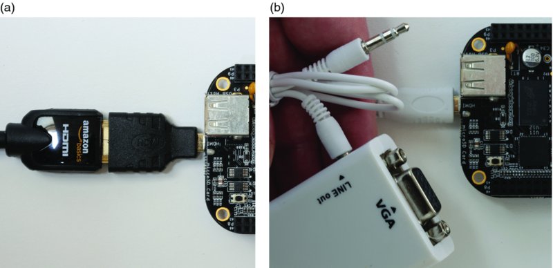
Figure 1-6 (a) BBB connected to micro‐HDMI‐to‐HDMI adapter and then to a low‐cost HDMI‐A‐to‐DVI‐D cable (b) A micro‐HDMI‐to‐VGA adapter with audio line output
USB to Serial UART TTL 3.3 V (for Finding Problems)
The USB‐to‐serial UART TTL serial cable is one accessory that is really useful when there are problems with the Linux distribution on your board. I find it invaluable when finding and fixing problems with my students’ boards. It connects to the 6 pin J1 header, which is beside the P9 header on the BBB. The black side of the cable is connected to pin 1 (the white dot) and the green side is closest to the USB host connector (see Figure 1-7). Only three pins are used on the BBB: pin 1 ground (black), pin 4 receive (orange), and pin 5 transmit (yellow).
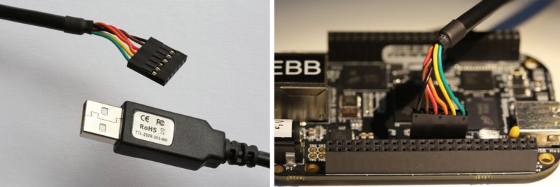
Figure 1-7 The USB‐to‐TTL 3.3V serial cable and its connection to the BBB (connection colors are black, brown, red, orange, yellow, and green)
Please ensure that you purchase the 3.3 V level version and ideally purchase a version with a six‐way 0.1” female header pre‐attached (it does sell with only bare wires, which I purchased by accident!). This cable contains a chipset and requires that you install drivers on your desktop computer, creating a new COM port. The FTDI TTL‐232R‐3V3 cable works very well and provides a very stable connection (about $20). See tiny.cc/ebb102 for the datasheet and the “VCP” link to the software drivers for this adapter cable.
If you are planning to flash your own images to the BBB or if you have a board that is not booting, I recommend that you purchase one of these cables. The use of this cable is discussed in Chapter 2 and Chapter 3.
Optional Accessories
The following sections describe optional accessories that you may need, depending on the applications that you are developing (see Figure 1-8).
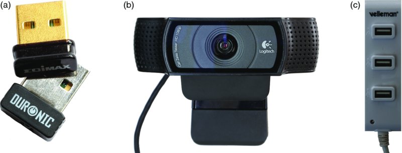
Figure 1-8 (a) USB Wi‐Fi adapters; (b) the Logitech C920 camera; and (c) a Velleman USB hub (bus powered)
USB Hub (to Connect Several USB Devices to a USB Host)
If you are planning to connect more than one USB device to the BBB at the same time, then you will need a USB hub. USB hubs are either bus powered or externally powered. Externally powered hubs are more expensive; however, if you are powering several power‐hungry adapters (Wi‐Fi in particular), then you may need a powered hub. Ensure that you plug the USB hub into the BBB host connector before powering on the BBB. I have tried different brands of USB hub and they have all worked without difficulty.
Micro-HDMI to VGA adapters (for VGA Video and Sound)
Several low‐cost micro‐HDMI‐to‐VGA adapters are for sale (e.g., on Amazon or eBay) for converting the HDMI output to a VGA output. As well as providing for VGA video output, many of these connectors provide a separate 3.5 mm audio line out, which can be used if you wish to play audio using your BBB, without requiring a television, high‐end amplifier, or monitor (see Figure 1-6(b)). There are also USB audio adapters available that can provide high‐quality playback and recording functionality. These adapters and their usage are described in Chapter 12.
Wi-Fi Adapters (for Wireless Networking)
Many different Wi‐Fi adapters are available, such as those in Figure 1-8(a); however, not all adapters will work on the BBB. The Linux distribution and the chipset inside the adapter will determine the likelihood of success. You can find a list of adapters that are confirmed as working at tiny.cc/ebb103. However, please be aware that manufacturers can change chipsets within the same product and that buying an adapter from the list does not guarantee that it will work. You are more likely to succeed if you can confirm the chipset in the adapter you are planning to purchase, and evaluate that against the list. Wi‐Fi configuration and applications are discussed in detail in Chapter 10, which tests a range of different low‐cost adapters that are widely available.
USB Webcam (for Capturing Images and Streaming Video)
Attaching a USB webcam can be a low‐cost method of integrating image and video capture into your BBB projects. In addition, utilizing Linux libraries such as Video 4 Linux and Open Source Computer Vision (OpenCV) enables you to build “seeing” applications.
In Chapter 12, different webcams are examined, but the text focuses on the use of the Logitech C920 webcam in particular for video streaming applications (see Figure 1-8(b)). It is a relatively pricey webcam (at about $70) but it is capable of streaming full HD video directly using the BBB, as it has H.264/MPG‐4 hardware encoding built into the camera. This greatly reduces the workload for the BBB, allowing the processor to be available for other tasks. As with Wi‐Fi adapters, it would be useful to confirm that a webcam works with the BBB before you purchase it for that specific purpose. I test several camera types in Chapter 12.
USB Keyboard and Mouse (for General-Purpose Computing)
It is possible to connect a USB keyboard and mouse separately to a USB hub or to use a 2.4 GHz wireless keyboard and mouse combination. Very small wireless handheld combinations are available, such as the Rii 174 Mini, Rii i10, and eSynic mini, all of which include a handheld keyboard with integrated touchpad. A USB Bluetooth adapter is also useful for connecting peripherals to the BBB. A similar Bluetooth keyboard/touchpad is used in Chapter 11.
Capes
Capes are daughterboards that can be attached to the P8/P9 expansion headers on the BeagleBone. They are called capes (as in Superman’s cape!) due to the shape of the boards as they wrap around the RJ-45 Ethernet connector. You can connect up to four capes at any one time, when they are compatible with each other.
Some capes use a significant number of pins. For example, you will look at the LCD4 cape in Chapter 11. It uses the P8 header pins 27 through 46 and some of the analog inputs for its buttons and resistive touch interface. If you are using the eMMC for booting the BBB, then very few pins remain for GPIO use. In addition, the LCD cape does not carry forward the pin headers. Figure 1-9 shows two views of this cape when connected to the BBB, running the standard BBB Debian Linux distribution.
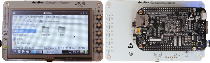
Figure 1-9 The LCD4 cape (top and bottom view)
More than 50 capes are currently available for the BeagleBone; a full list can be found at www.beagleboard.org/cape. Here is a selection of some example capes that you might find useful in your projects (see Figure 1-10):
- The LCD capes are available in different sizes: 7” (800×480), 4” (480×272), and 3” (320×240), with the 4” version captured in Figure 1-9. They have resistive touch screens, meaning you use a stylus (or fingernail) to interact with the screens. This is different than the capacitive touch screens on recent phones/tablets.
- The Adafruit Proto cape is a low‐cost (∼$10) bare cape, which you can use to transfer your breadboard design to a more solid platform. Several other breadboard and prototyping capes are available.
- The Replicape ($179) is an impressive open‐source 3D printer cape that has five stepper motor drivers, including micro‐stepping support. See
www.thing‐printer.comfor more information. - The Valent F(x) LOGi‐Bone FPGA development board cape ($89) adds FPGA capabilities to the BBB with a Spartan 6 LX9. FPGAs provide programmable logic blocks that allow for very fast I/O operations, but does so with an increase in complexity. This cape also provides an Arduino header, enabling it to interface directly to shields that have been developed for the Arduino platform. This cape is discussed briefly at the beginning of Chapter 13.
- There are camera capes such as the 3.1MP Camera cape from
www.beagleboardtoys.comthat provides an alternative to USB webcams; however, it cannot be used at the same time as the eMMC, so the BBB must be booted from the micro‐SD card.
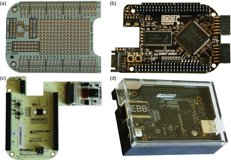
Figure 1-10 (a) The Proto cape; (b) Valent F(x) LOGi‐Bone; (c) Camera cape; and (d) Adafruit BBB case
You have to be very careful about compatibility when interconnecting capes. There is a compatibility table covering the more common capes at tiny.cc/ebb104. The preceding list is just a small selection. Many more capes are available and it is likely that additional capes will be developed over time.
How to Destroy Your BeagleBone!
The BBB and BBW are complex and delicate devices that are very easily damaged if you do not show due care. If you are moving up from boards like the Arduino to the BeagleBone platform, then you have to be especially careful when connecting circuits that you built for that platform to the BBB. Unlike the Arduino Uno, the microprocessor on the BBB cannot be replaced. If you damage the microprocessor, you will have to buy a new board!
Here are some things that you should never do:
- Do not shut the BBB down by pulling out the power jack/USB power. You should shut down the board correctly using a software shutdown (e.g., by pressing the power button once) or by holding the power button for about eight seconds for a “hard” power down. This enables the PMIC to shut down the board correctly. If you have to remove power by disconnecting the power supply, hold the reset button while doing so in order to lower system power usage.
- Do not place a powered BBB on metal surfaces (e.g., aluminum‐finish computers) or on worktops with stray/cut‐off wire segments, resistors, etc. If you short the pins on the P8/P9 headers you can easily destroy your board. You can buy a case from suppliers such as Adafruit (see Figure 1-10(d)). Alternatively, you can attach small rubber feet to the BBB.
- Do not connect circuits that source/sink other than very low currents from/to the P8/P9 headers. The maximum current that you can source from many of these header pins is 4‐6 mA and the maximum current you can sink is 8 mA. The power rail and ground pins can source and sink larger currents. The Arduino allows currents of 40 mA on each input/output. This issue is covered in Chapter 4 and Chapter 6.
- The GPIO pins are 3.3 V tolerant (the ADCs are 1.8 V tolerant). Do not connect a circuit that is powered at 5 V or you will destroy the board. This is discussed in Chapter 4, Chapter 6, and Chapter 8.
- Do not connect circuits that apply power to the P8/P9 pins while the BBB is not powered on. Make sure that all self‐powered interfacing circuits are gated by the 3.3 V supply line. This is covered in Chapter 6.
Here are two steps that you should always follow:
- Carefully check the pin numbers that you are using. There are 46 pins in each header, and it is very easy to plug into header connector 21 instead of 19. For connections in the middle of the headers, I always count twice—up from the left and down from the right. In addition, there is a very useful set of P8/P9 labels available at
tiny.cc/ebb105that you can print at 100% scale and attach to your BBB, as illustrated in Figure 1-1. - Read the SRM in detail before connecting complex circuits of your own design to the BBB.
If your BBB is dead and it is your fault, then I’m afraid that after you perform all of the checks at www.beagleboard.org/support, you will have to purchase a new board. If it is not your fault, then see the BBB SRM manual and www.beagleboard.org/support website to return a defective board for repair by requesting a return merchandise authorization (RMA) number.
Summary
After completing this chapter, you should be able to:
- Describe the capability of the BeagleBone and its suitability for different project types.
- Source the important documents that will assist you in working with the BBB platform.
- Describe the major hardware systems and subsystems on the BBB.
- Identify important accessories that you can buy to enhance the capability of your BBB.
- Have an appreciation of the power and complexity of the BBB as a physical computing platform.
- Be aware of the first steps to take in protecting your board from physical damage.
Support
The key sources of additional support documentation are listed earlier in this chapter. If you are having difficulty with the BeagleBone platform and the issues are not described in the documentation, then you should use these two resources:
- The BeagleBoard Google Group, which is available at
groups.google.com/d/forum/beagleboard. Please read the frequently asked questions (FAQs) and search the current questions before posting a new question. - There is a live chat available at
www.beagleboard.org/chator directly on the Beagle IRC channel (by joining#beagleonirc.freenode.net) using a free IRC client such as X‐Chat for Linux, HexChat for Windows, or Colloquy for Mac OS X.
Please remember that the people in this group and IRC channel are community members who volunteer their time to respond to questions.