
This chapter will go over an example of some basic usage of a physics component called the Configurable Joint, which can be used to bind GameObjects together with the physics system. We’ll use it to create a chain of objects, each one attached to the one above it to create something like a rope. At the bottom of the rope, we’ll attach a platform that will swing with the rope. Our player can use their “telekinesis” to pull the swing or its joints and then jump on the platform to ride it.
Swing Setup
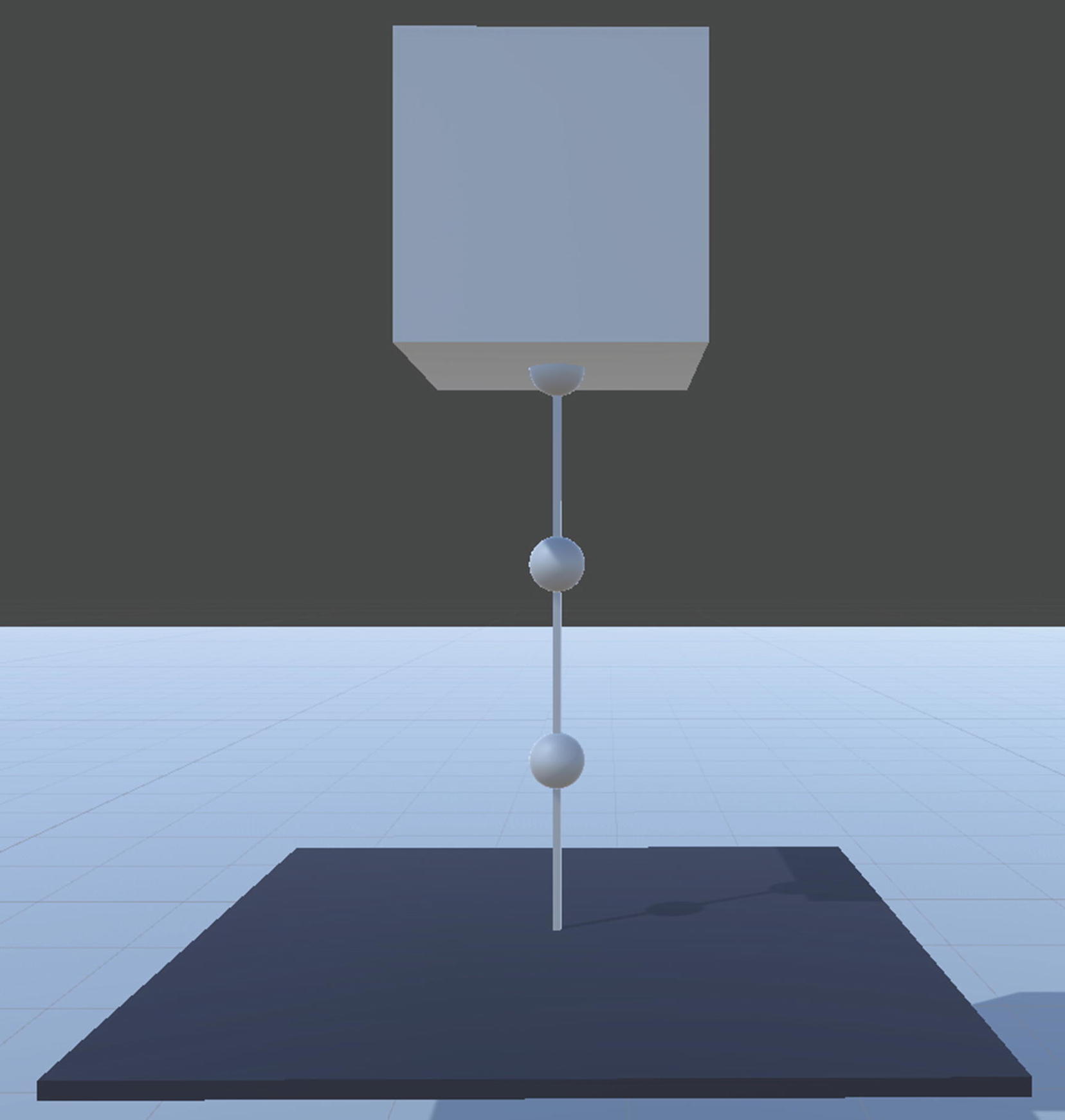
The full Swing GameObject hovering above the floor, consisting of the Hovering Cube on top, three Chain Links hanging below it, and a Platform cube connected at the bottom
Start by creating an empty GameObject named “Swing” with no parent. We’ll use this as a root for the Swing. We’ll be able to select it to move the whole Swing and all its pieces wherever we want.
Add a Cube child to the Swing. Name it Hovering Cube. Set its scale to (10, 10, 10) and its local position to (0, 35, 0). Set its layer to “10: Unmovable”.
Add an empty child GameObject to the Swing. Name it Chain Link and set its local position to (0, 30, 0).
Add a Sphere child to the Chain Link. Leave its local position at (0, 0, 0) and set its scale to (2, 2, 2).
Add a Cube child, also to the Chain Link. Set its scale to (.3, 5, .3) to make it slender and long. Set its local position to (0, –3.5, 0) to place it just beneath our Sphere.
After we set this one Chain Link up, we’ll be copy-pasting it to create the others. But first, let’s make sure it has the components we need so we aren’t adding them and setting them up three times.
We’ll need each Chain Link root GameObject (not the Sphere or Cube within) to have a Rigidbody and a Configurable Joint added. Go ahead and add each of those now and give the Rigidbody a Mass value of 1.5.
You might think we should add a Rigidbody not to our Chain Link, but to both the Sphere and the Cube within it, but this isn’t necessary.
The Rigidbody of the Chain Link will detect the Box Collider and Sphere Collider of its child GameObjects and will consider them fused together to form a single body, acting as if both of those colliders are part of the same object. We can effectively think of them as two pieces of metal welded together. If the Cube is struck by something, then it moves and the Sphere pivots with it – and vice versa.
These are known as compound colliders and can be used to represent a more complex object by shaping it out of “primitive” collider types. Primitive colliders are the colliders for basic built-in shapes: Box Collider, Sphere Collider, and Capsule Collider. By creating a parent GameObject with a Rigidbody attached, then adding children with primitive colliders, we create one whole object with a more complex shape than just a cube, sphere, or capsule.
You can do this to “summarize” the shape of a more complex mesh with a combination of primitive shapes.
Moving on to our Configurable Joint, we have a few values to set.
The Configurable Joint component is attached to the GameObject that you want to connect another GameObject to, and the Rigidbody of the other GameObject is referenced in the Configurable Joint. So when making a chain out of these Chain Link objects, this means that the Configurable Joint will be attached to the upper (higher) link in the chain, and the link beneath that chain will be referenced as the “Connected Body” member (the first member listed in the Inspector).
The Anchor value of the Configurable Joint is a Vector3 depicting from where the Connected Body pivots. The location is local to the Transform of the GameObject with the Configurable Joint component. We want our Anchor to be at a value of (0, –6, 0).
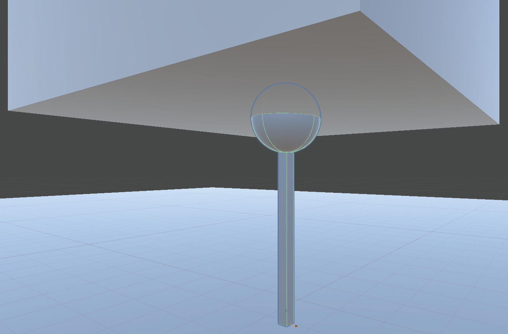
The Chain Link is shown sticking out of the bottom of our Hovering Cube. The Configurable Joint Anchor location is visible at the bottom of the Chain Link Cube as a small set of arrows
This will ensure that the Chain Link we position below this one will be pivoting around the bottom of this link, not the center of the Sphere (which would be quite awkward).
Moving on, the six “Motion” and “Angular Motion” dropdown fields in the Configurable Joint are all that’s left to set.
When Locked, the axis is not changed by the joint at all.
When Limited, the axis is affected, but limited by the other fields that can be customized down below.
When Free, the axis can move as much as warranted with no limitations.
For our purposes, we’ll set all three of the Motion fields to Locked because we don’t want the joints to cause movement, just rotation – they pivot around each other.
If we allow angular X motion, the chain links can swing forward and back.
If we allow angular Y motion, the chain links can twist sideways, allowing the platform to turn.
If we allow angular Z motion, the chain links can swing right and left.
The swing will be more controlled if you only allow it to pivot on the X or Z axis and lock the other two. The Y axis isn’t all too important, simply depicting whether we’ll see the cubes twisting and turning from the forces applied to them.
For our tests, let’s set the X angular motion to Free and set both the Y and Z angular motions to Locked. This will allow it to swing forward and back only, something like a pendulum. Since this is all local to the Transform, if you want it to swing left or right instead, you can just rotate the entire Swing on the Y axis instead of changing the Configurable Joint settings.

Our Rigidbody and Configurable Joint components shown in the Inspector
Select the Chain Link and copy-paste it. With the copy selected, decrease its Y position by 7 units in the Inspector. You can do this by simply typing a “– 7” after the current Y position value in the field, and Unity will calculate the new value as soon as you click away from the field. This will position the second Chain Link so that the bottom of its Sphere is just beneath the Cube of the upper link. If you’d rather type the value in yourself, it should be a Y position of 23.
Again, copy and paste the Chain Link we just made, and apply the same –7 units to the Y axis so the Y position is 16.

Our entire Swing object while selected. Each Configurable Joint Anchor is also shown at the bottom of each Cube
Add a Cube child to the Swing GameObject. Name it Platform. Set the scale to (25, .5, 25) and position it at (0, 9.75, 0) so it’s just beneath the lowest Chain Link.
Add a Rigidbody component to the Platform. To prevent the platform from colliding with the player and tilting about, check all three Freeze Rotation boxes. Set Mass to 4 and Drag to .15.
I’ll add the existing MovingPlatform material to the cube as well, giving it a dark-blue color.
With that, our setup of the bits and pieces of our swing is complete, which means your swing should at last look like it does in Figure 39-1 from before.
Connecting the Joints
In order to connect the joints to each other, we’ll first want to connect the upmost Chain Link to the Hovering Cube itself.
To add a Configurable Joint component, you will have to add a Rigidbody as well. Trying to add one without a Rigidbody already attached will result in Unity automatically adding one.
Since we don’t want our Hovering Cube to be affected by any collisions or forces, we’ll constrain its position and rotation through the Rigidbody. Check all six boxes under the Constraints field of the Rigidbody in the Inspector. You can also uncheck the Use Gravity field, since it wouldn’t make much sense to apply gravity when we’ve already frozen our Rigidbody in place.
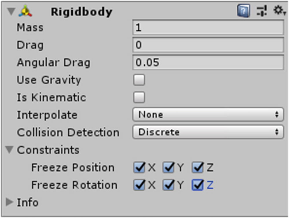
Rigidbody settings in the Inspector for our Hovering Cube
Now we have the Hovering Cube anchored in place above the ground, so if we attach our first Chain Link to it by a Configurable Joint (which we’ll do in a second), the link will be bound to the Hovering Cube by that joint, keeping it from falling freely through the air. With the other links attached to that one, they’ll all hang off the Hovering Cube.
With a Configurable Joint added to your Hovering Cube, don’t forget to set the Anchor to the bottom of the cube with a value of (0, –.5, 0). Remember, the Anchor is local to the Transform, so each unit in the Anchor is multiplied by the Transform scale. For our Chain Links, the scale was (1, 1, 1) so the Anchor value was effectively in world units, but since our Hovering Cube is scaled to (10, 10, 10), that means each unit in the Anchor setting is worth 10 world space units. That’s why it’s –.5 to put it at the bottom of the Cube, not –5. Think of it as “50% of the height of the cube,” not “.5 units”.
We also need to lock our Motion values in the Configurable Joint of the Hovering Cube. Following the same settings you used on the Chain Links, shown before in Figure 39-3, apply them again to the Hovering Cube: set all six fields to Locked except for the Angular X Motion, which should remain set to Free.
Chain Link is the highest one.
Chain Link (1) is the middle one.
Chain Link (2) is the lowest one.
So first, select the Hovering Cube and drag Chain Link (the topmost one) from the Hierarchy onto the “Connected Body” field of the Configurable Joint. This binds the first Chain Link to the Hovering Cube.
Chain Link should have its Connected Body set to the Rigidbody of Chain Link (1).
Chain Link (1) should be set to Chain Link (2).
Finally, Chain Link (2) should have the Platform Rigidbody as its Connected Body, which binds the Platform to the bottom link.
Finishing Touches
You should now be able to play the game, run over to your Swing with the Player, and try pulling and pushing the Platform or the Chain Links with the Telekinesis feature. Remember, the swing has been set to only swing on the X axis, which is forward and backward. This means it’s like a pendulum, swaying back and forth in only one direction. Trying to pull and push it from the wrong side won’t generate much of a reaction.
With our current gravity settings, the swinging may seem a bit “off.” Unity’s default gravity settings are tweaked to appear realistic when the unit of measurement for your game is 1 meter. As you’ll recall from our earliest chapters, what a single unit resembles is totally relative. Since our player is 6 units tall, we’re really using a unit measurement of about 1 foot. The gravity setting thus thinks we’re a bit larger than we really are: the player would be 6 meters tall by that standard, not 6 feet! This can account for the swing moving in a somewhat “slow-motion” way.

In the Project Settings window, the Physics tab is selected, exposing the Gravity field
This shows a Vector3 for the gravity force applied to Rigidbodies constantly (per second). Of course, the X and Z axes are set to 0 since gravity does not standardly pull you in such directions. The Y axis is what we want.
The default setting of –9.81 mimics the pull of gravity on Earth but using meters as a measurement. Since a meter is about 3.28 feet, we can multiply this default setting of 9.81 by 3.28, which is roughly 32.2. Of course, it should be –32.2 since we want it to be downward force.
Once you’ve set the gravity this way, your swing movement should look more natural.
One final touch is to add a Platform script to our Platform cube GameObject. Once you’ve done that, try setting the swing in motion with Telekinesis and then hopping onto it. The Player should stick to the swing and move with it.
As expected, since everything involved in the motion of the Swing is driven by the physics system, other Rigidbodies will stay on the swing and move with it as well. Try stacking some Rigidbody cubes on top of the swing and then set it in motion with Telekinesis.
Summary
Box Colliders, Sphere Colliders, and Capsule Colliders are considered primitive collider types. These are the most basic and cheap collider types.
A parent GameObject with a Rigidbody attached will consider all its children with primitive Collider components to be part of the same whole object. When one collider is struck, it’s as if they were all struck, since the Rigidbody considers them one attached unit.
The Configurable Joint component should be attached to the GameObject to which the other Rigidbody is attached. The “Connected Body” field refers to the Rigidbody that should be attached to the GameObject with the Configurable Joint component.