3
Let’s Get Soldering
Finally, we’re at the part where you get to fire up your iron and learn to solder. It might seem like we went through a lot to get to this point, and you’re right—we did. Just remember that all the information, tips, tricks, and recommendations came from years of experience. My hope is that I will save you a lot of time and money and, more importantly, make the learning process fun by helping you avoid some of the bad tools and materials that I have seen over the years.
Simply learning to solder takes just a few minutes, especially when you have the right tools. Thousands of people have learned to solder at Maker Faires all over the world, and it took less than 10 minutes for most of them to learn the basics. OK, let’s get started!
Preparing Your Soldering Iron and Workstation
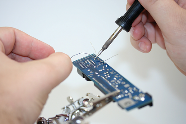
When you start your project, it is very important to have a safe place to solder with good light and adequate ventilation. Remember: your kitchen table isn’t a proper place to solder. However, if you need to solder somewhere that is less than ideal, you can always put down a scrap piece of plywood to protect the surface you are working on. If you are using lead-based solder, do not work anywhere with food preparation in its future. You can see in Figure 3-1 that I have all the required tools and materials ready to go. You don’t want to be running around looking for things once your iron is hot—you never want to leave a hot soldering iron unattended.
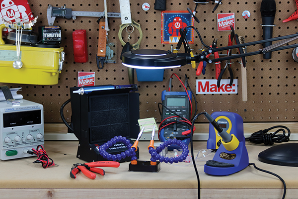
Figure 3-1: A proper spot to solder
Before you start using a brand-new iron, you will need to prep the tip, which is called tinning the tip. (See Figure 3-2.) This allows the solder to flow more easily when making connections, and it protects the soldering iron tip from corrosion. It’s a simple process. Just turn your iron on to about 650°F (340°C) if you are using lead-based solder, or 700°F (370°C) if using lead-free solder. Once the iron is hot, simply melt some solder on the tip, making sure it’s completely covered. Once it’s covered in solder, give it a quick wipe on your solder sponge or brass sponge. It should look nice and shiny, and be ready to use.

Figure 3-2: A new soldering iron tip waiting to be tinned
This process of cleaning and tinning the tip should be repeated as much as necessary to make sure your soldering iron tip is always clean. I wipe mine about every three solder connections, and every time I pick up my iron or put it back on the stand. If you plan on not soldering for more than 10–15 minutes, turn your iron off. This will help minimize the oxidation that will inevitably occur on the tip of your iron. One of the biggest mistakes I see when someone is learning to solder is attempting to solder with a very dirty tip (shown in Figure 3-3). It just makes for a bad connection and experience. One last thing to remember is that after you are done soldering, go ahead and tin and wipe the tip again (see Figure 3-4). This will leave a nice protective coating of flux and solder on your tip while not in use.
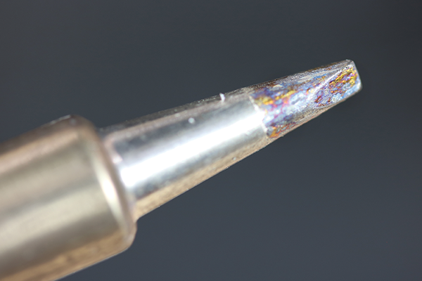
Figure 3-3: A dirty soldering iron
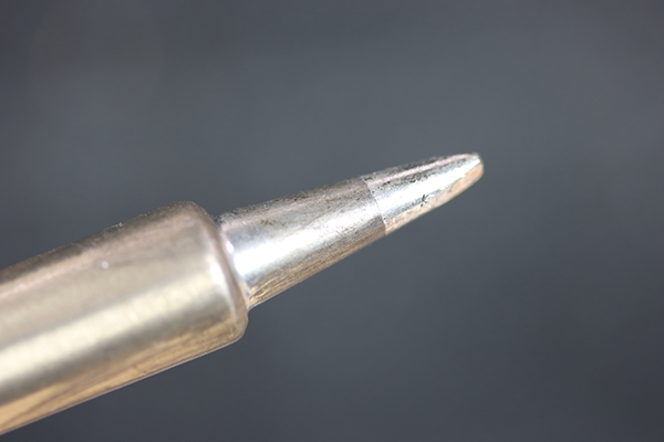
Figure 3-4: The tip after cleaning
If your soldering iron tip gets really corroded, you can use tip-tinning paste to try and restore the tip (see Figure 3-5). It’s readily available and easy to use—just heat the tip up, and dip the tip in the tin repeatedly. It should restore the tip with just a few applications. If not, you’ll need to install a new tip on your soldering iron. It works so well that I also like to use it once in a while just for regular maintenance. A small, inexpensive tin will last for years.
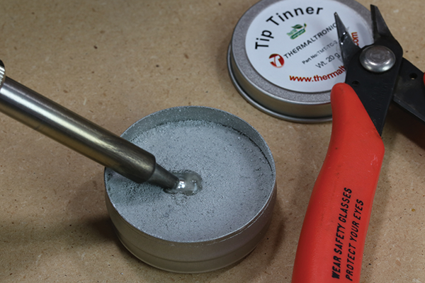
Figure 3-5: Using tip-tinning paste
Soldering Printed Circuit Boards (PCBs)
It seems like most people dive right into soldering printed circuit boards. I think it’s because there are so many amazing kits to solder together—from simple blinky LEDs to Internet-connected devices, and more. There are thousands of different kits made by hundreds of different kit makers, like myself, so it’s no wonder so many Makers want to learn to solder. Regardless of the reason, it’s a popular first soldering project, so that’s where I’ll start.
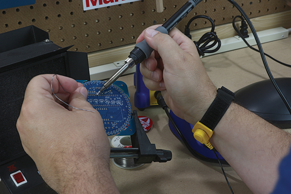
Figure 3-6: Wearing an antistatic band
If you are soldering a few wires together, or the components you are using aren’t sensitive to static, you may not need an anti-static wristband (shown in Figure 3-6). It’s always a best practice to ground yourself to avoid any static that may be present, but the truth is that most people don’t use them in hobby electronics—I have one, but rarely use it. If you are working in a lab or a professional environment, you will see them in use everywhere. They are extremely important when working on expensive integrated circuits (ICs) or complex or expensive boards, or when there is a threat of static electricity. I’m willing to take the chance of not wearing one when soldering a project, mostly because I would use a socket that allows me to plug in the IC after all soldering is done. This also allows me to replace the ICs in the future, as needed, without having to desolder the IC.
In most cases, your PCB will be ready to use out of the box, but I have seen some that have enough corrosion from manufacturing or extended storage that they needed to be cleaned. Fortunately, dirty boards are not too common, and if you get one, they’re easy to clean. I keep a few electronic-specific isopropyl wipes handy for just this purpose. Just wipe the board down, as shown in Figure 3-7, and be sure to properly dispose of the wipe. There are also dosing bottles and pads that you can pick up for this purpose, but those are usually only found in a facility that is soldering a lot of PCBs.
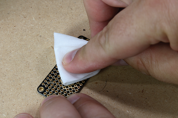
Figure 3-7: Wiping your soldering connection clean
First, you will need to place the parts on the PCB. We’re not going to cover the specifics of how to do this, because the instructions that came with your kit should cover those details. Instead we’ll start with how to make the mechanical and electrical connections once the parts are placed. A common mistake people make when starting out is not properly holding the parts in place while they are preparing to solder. You should insert the part into the board and bend the wires at about a 45° angle, as shown in Figure 3-8, which will keep the part in place while you solder the connection.

Figure 3-8: Bending wires to keep parts in place
Most beginners tend to bend the wires flat to the back of the PCB, as shown in Figure 3-9. Do not do this! This will cause electrical shorts, and make the soldering and trimming of the leads much more difficult. You only need to bend them enough so that the part doesn’t move when you solder the connection. Remember: in most cases, you will flip the board over to solder the component in place. If the wire leads aren’t bent, the part will fall out. Skip to Chapter 4, “Troubleshooting and Fixing Mistakes,” to read more about how to fix mistakes like this one.

Figure 3-9: Wires bent too far down, which will lead to short circuits—don’t do this!
If your component, such as an IC socket, doesn’t have long leads, you can use tape to temporarily hold it in place. Tape will work if you don’t have any other means of holding a component, but make sure it’s attached to the PCB far away from where you are soldering so it doesn’t melt. Melted tape will leave behind residue that will need to be removed prior to soldering any more components. A much better option is to use copper clamps or alligator clips, as shown in Figure 3-10. You can find these clips in various sizes and made from various materials. It’s a good idea to have a few in your lab for tricky soldering jobs.
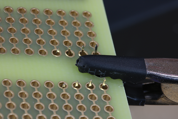
Figure 3-10: An alligator clip in the process of being used to hold a component in place
Now it’s time to solder! Make sure your iron is up to temperature. If you are unsure, you can touch the tip of the iron briefly to the solder to see if it melts. It should melt almost instantly. Be sure to wipe the tip clean prior to soldering.
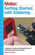
The key to a good solder joint is the placement of the tip of the iron (shown in Figure 3-11). It should be at the intersection of the PCB and the component lead. You should heat both parts of the joint so the solder flows to both the component and the PCB equally. How long you keep the iron in the joint varies a little bit based on the temperature of your iron, but no more than a second or two. In general, you can heat the connection for two seconds, then feed a little solder to the joint for about one second—again right at the intersection of the component and PCB—then remove the iron and allow the solder to cool.
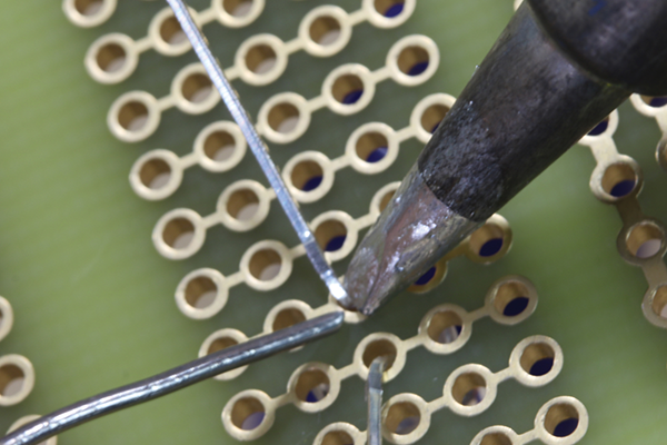
Figure 3-11: Proper placement of the soldering iron tip and the location of where to feed the solder
The entire process should only take about three to four seconds total. Any longer, and you might burn the PCB or the component, and the flux will start to lose its integrity and no longer work.
You will know that your timing is right when you see the “cone of perfection.” The solder joint should look fairly shiny and have the appearance of a little volcano, as shown in Figure 3-12. When solder is heated with flux to the ideal temperature and becomes fluid, you are creating a property of wetting at the connection point. Wetting is what happens when the solder penetrates the copper trace of the PCB and creates a new alloy. Proper wetting of the solder will not only create an ideal electrical connection between your component and PCB, but also create the strongest mechanical connection possible.

Figure 3-12: A perfect basic solder joint
If your solder joint doesn’t look like Figure 3-12, then skip on over to Chapter 4, where you will see examples of what might have gone wrong and how to fix a bad solder connection.
Some components, like USB ports and power jacks, have large lugs to help make an extra strong mechanical connection between them and the PCB (see Figure 3-13). Be sure to always add enough solder to these components, because they will experience stress every time they are used. You’ll be surprised how much solder can flow into these connections. Be ready for this by unspooling enough solder to fill in the holes of the PCB before you start.

Figure 3-13: A USB connector with four leads and two lugs
Trimming the Wire Leads after a Successful Soldering Connection
Once the solder connection is made, in most cases you will need to trim the wire lead. The exception to this rule is any component where the lead is short enough to not interfere with other components or the housing of your project. On the left of Figure 3-14, you can see the properly trimmed leads of an LED, and on the right you can see two rows of leads from an IC that didn’t need to be trimmed. When you’re trimming the wire leads, do not cut them flush with the PCB. You should trim the leads at the top of the solder cone, or about one-third of the way down the solder cone—no more. You do not want to cut them too close, as this will weaken the joint and possibly cause it to fail in the future.
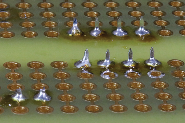
Figure 3-14: Wire leads untrimmed (left) and an IC that doesn’t need trimming (right)
On the left of Figure 3-15, you can see a solder connection that was trimmed way too close to the PCB. This may weaken the electrical and mechanical connection in the future. There is no need to trim the leads this close. On the right, you can see a lead that could use a bit more trimming. It protrudes enough that it could get hung up on another component or interfere with installing it in the plastic housing.
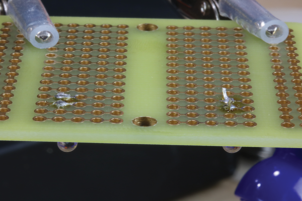
Figure 3-15: Too close of a trim (left) and too much wire lead (right)
Connecting Wires or Components Without a PCB
Not all soldering occurs at the intersection of a PCB and a component lead. Many times, you will need to solder some wires or components directly to each other. Although this is a simple process, I will share some tips and tricks to make it a perfect connection.
It can be very tempting to solder wires together by laying them directly on your work surface. Don’t do this! You will almost certainly burn your work surface, make the tip of your iron dirty, and worst of all create a disturbed solder joint that is mechanically unsound. Instead, use your third hand to hold the wires securely in place.
Prior to soldering, make sure to twist the wires together, making a solid connection. Then, flood the connection with plenty of solder.
In Figure 3-16 you can see the heat-shrink tubing on the jaws of the third hand. This prevents the teeth from slicing into the exterior insulation of the wire, which might cause a short or allow moisture into the connection. If the wires are attached to other components, don’t forget to add the heat-shrink tubing to the wire prior to soldering the connection. (More about heat-shrink tubing a little later on.)
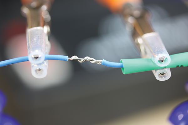
Figure 3-16: Wires ready for soldering
NASA has high standards when it comes to splicing two wires together. They use a process called a lineman’s splice, and although it’s unlikely that you are building something that requires such scrutiny, when it comes to soldering a connection between two wires, it’s tough to beat the lineman’s splice, shown in Figure 3-17. In the figure, you can see the pre-tinned wires pass each other, and then wrap three times around each other, forming an incredibly robust connection. (You should always wrap the wires a minimum of three times.)

Figure 3-17: NASA lineman’s splice
Once you wrap the wires, trim the ends flush and cover the entire area with a generous amount of solder, as seen in Figure 3-18, then cover the connection with heat-shrink tubing, as in Figure 3-19. If you want your wire connections to last a long time, take some advice from NASA and use a lineman’s splice.
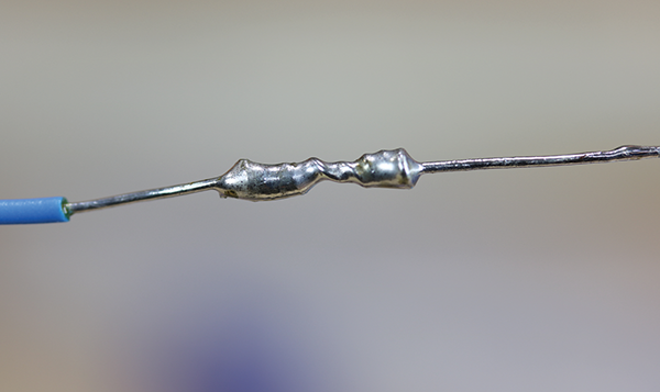
Figure 3-18: Wires after being soldered together
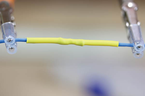
Figure 3-19: Wires insulated with heat-shrink tubing
Some components, such as motors and switches, will have terminals that you will need to make connections to (as shown in Figure 3-20). In general, your best bet is to use stranded wire, since it’s more flexible and will perform better—but solid-core wire will work, too. Do not just place the wire on the terminal and solder, which is something I see far too often.
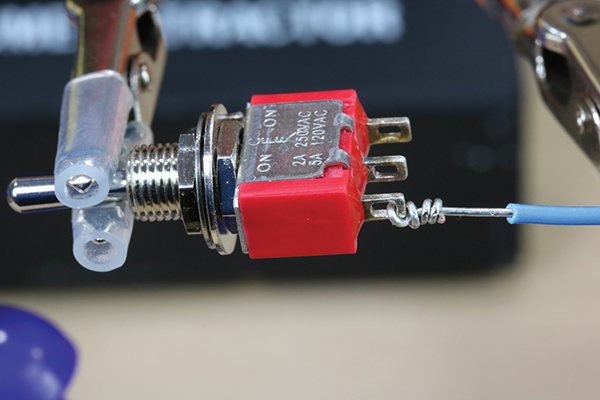
Figure 3-20: Soldering wires to the terminals of components
Take the time to fish the wire through the terminal and do the lineman’s splice, which we learned how to do earlier and is shown in Figure 3-17, and applied to a switch, as shown in Figure 3-20. This will give you a lot of surface area to make a good mechanical connection. If there is no hole for the wires to go through, you can pre-tin the terminal with some solder, then place the wire on the terminal and heat the connection after wrapping it. In either case, the solder will flow onto the wire and terminal, making the connection (see Figure 3-21).
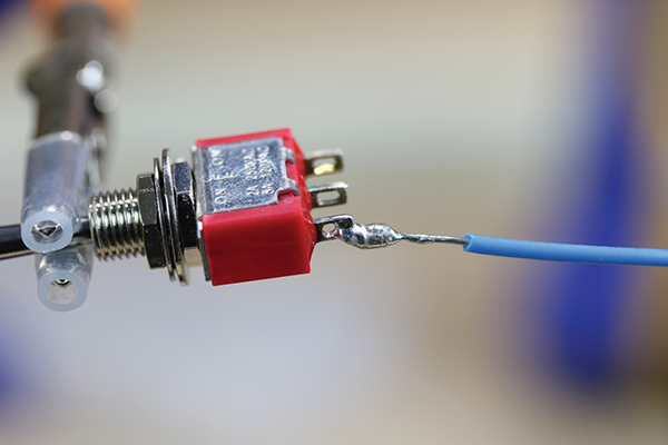
Figure 3-21: Wire successfully soldered to the terminal of a switch

Figure 3-22: Wire insulated after soldering
Once you make a connection, especially when it’s a splice between two wires, you need to protect that connection from shorts and corrosion. You can use electrical tape to secure it, but that typically fails, and it can add a lot of bulk, which can be undesirable for hobby electronics where space is limited. Your best option for sealing the connection is to use heat-shrink tubing (shown in Figure 3-22). There are several different kinds of heat-shrink tubing, but most function the same—when heat is applied, the tubing will shrink to approximately half its diameter.

Figure 3-23: Heat-shrink tubing
Start by selecting a piece of heat-shrink tubing that is longer than the exposed wire, and slightly larger than the connection. You will need to slip it onto the wire and away from the connection before soldering. After you have soldered the wires, move the heat-shrink tubing over the bare metal of the wires and apply heat to it. This will make it shrink, and prevent shorts in your circuit. It’s fairly common to use a lighter to heat the tubing, but I encourage you to use a hot-air tool instead. I’ve seen tubing catch fire and burn far too often. The type of hot-air gun I’m using in Figure 3-23 costs less than $20 USD and it’s a lot safer than an open flame.
Another alternative would be to use liquid electrical tape. Although this works, I find that it makes a bit of a mess and don’t use it too often. If I’m going to be totally honest, I usually resort to using it after I have made a connection and forgot to put heat-shrink tubing on the wires first. Don’t laugh too hard; it will happen to you too!