5
Advanced Soldering
Up to this point, we have learned about soldering components that have two or more wire leads that are inserted into a printed circuit board (PCB). Now we are going to look at soldering surface-mount devices (SMDs), which is soldering components that lie directly on the PCB and may or may not have any wire leads. This type of soldering is called surface-mount technology (SMT) and is typically done with more advanced tools, and most often by a machine. But that doesn’t mean you can’t do it by hand, and that’s what this chapter is all about.

There are a few reasons that you would want to use an SMD. The first would be that the component you want to use is only available in a surface mount package. Electronics are constantly shrinking in size, and although there are plenty of hobby electronics people out there that would love a larger form factor, sometimes it’s just not an option. This mostly applies to higher-end sensors and integrated circuits (ICs), since there are still plenty of through-hole versions of LEDs, resistors, and ICs, with long leads that are easily soldered into a PCB. The other reason might be that you want to shrink your project down a little bit. I find myself using surface-mount LEDs all the time, since they are small and easy to solder. And to be honest, sometimes they just look cool, too. (See Figure 5-1.)

Figure 5-1: Soldering an SMD with a standard soldering iron.
You might be asking yourself if you can really solder an SMD with a standard soldering iron. The answer is, yes—on one condition. The component you want to solder must have exposed leads. Parts without visible leads require a more complicated technique. Typically, they are soldered using either a hot air rework stationor a reflow oven. (If you want to learn more about hot air rework stations, see the sidebar “Surface-Mount Soldering? Maybe a Hot Air Rework Station Is for You.”) Those techniques are way beyond the scope of this book. Fortunately, there are a lot of components that have visible connection points, or leads that can easily be soldered by hand with a standard soldering iron.
There are a lot of things to learn when it comes to SMT, and I can’t cover all the details in this book, like the naming conventions, numbering, and specific form factors in this book. However, I can show you the basics and give you some tips and tricks. I want you to learn something that took me far too long to figure out—you can easily solder many different kinds of SMDs with just a regular soldering iron!
Tools
I mentioned that you can solder surface-mount components with a standard soldering iron, and although that is completely true, there are a few extra tools and materials you might want to consider adding to your workbench to make handling the components a lot easier.
The most difficult part about learning to solder surface-mount components is the physical size of the components themselves—some SMDs make a grain of rice look big! That’s why you are going to need some type of magnification to be able to solder the components, and to inspect the solder connections afterwards for shorts and any solder bridges formed from excess solder at the connection. In Figure 5-2, you can see the two different magnifying glasses that I use. I use the pair on the right with the grey strap for prolonged soldering sessions. They work better for me, but they aren’t as comfortable as the black-framed version on the left. You can use a simple magnifying glass or jeweler’s loupe, but those typically require an extra hand, and you’re going to need both hands free to solder these small components.

Figure 5-2: Magnifying glasses
In the past, I used a stereo microscope to solder surface-mount components, but after it was damaged beyond repair, I started to look for a more affordable alternative. Even a used stereo microscope will cost you hundreds of dollars, and I thought there had to be a better option. For a very short period of time I used a USB microscope, but although it was priced right at only about $30 USD, having to connect it to a computer was not always practical. Then, I discovered the self-contained digital microscope, pictured in Figure 5-3, and my soldering experience improved dramatically. It’s incredibly easy to use, and has an internal rechargeable battery, dimmable lights, and a simple focusing system. You can even take pictures and store them on a micro SD card. What really sold me was the price—you can find them for about $60 USD online. Several different companies offered them, but they all had the same specifications and looked the same. I chose mine based on price and shipping, and it was well worth the investment. I use it all the time, and not just for soldering.
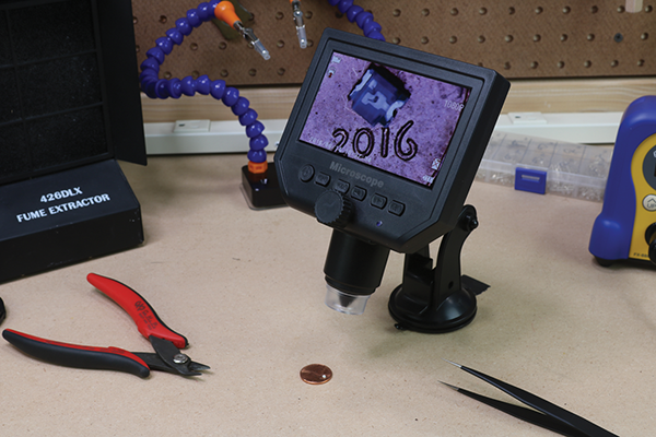
Figure 5-3: Self-contained digital magnifying microscope
As we discussed, handling small surface-mount technology (SMT) components can be challenging, so that’s why you will need at least one pair of good tweezers, similar to the ones shown in Figure 5-4. These types of tweezers have tips that are either straight or curved, and both will work equally well. Make sure they are electrostatic discharge (ESD) safe and non-magnetic so they will not damage any of your components. Using a good pair of tweezers to place those tiny components will save you hours of frustration.

Figure 5-4: ESD-safe tweezers
When working with SMT you will most likely not use a third hand tool as much as you would when using standard through-hole components. Most people lay the board flat on their work surface, since there are not any wires going through the board. For this reason, you should invest in a high-quality silicone mat (shown in Figure 5-5). Not only will it protect your work surface from excessive heat, but it will also help keep all your components organized. If you plan on just using a soldering iron, a silicone mat isn’t essential, but if you plan on doing any rework in the future, this is a must-have for your workbench. When selecting a mat, make sure it is specifically for soldering, as it needs to be able to handle high heat.
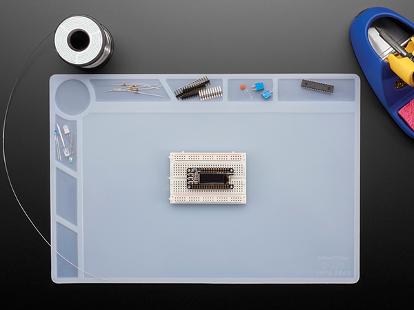
Figure 5-5: Insulated silicone rework mat
Image courtesy of Adafruit Industries, CC BY-NC-SA 2.0.
One of my favorite SMT tools is my “One PCB to Ruler Them All” from Adafruit Industries (see Figures 5-6 and 5-7). This handy little two-sided ruler has the form factors (“footprints”) of almost all the different SMT packages, like QFN, TDFN, SOIC, SOP, and more. I won’t go into a lot of detail—that’s for another book—but basically, it’s the form factors of all the different manufactured components. It also has some other useful things, like wire gauge sizes, and of course it functions as a handy six-inch ruler. I use it all the time just to get an idea of how small or large a component will be.
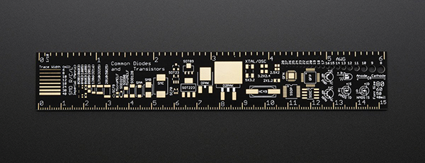
Figure 5-6: The front of the “One PCB to Ruler Them All”
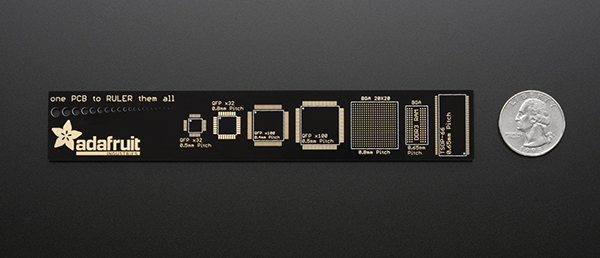
Figure 5-7: The reverse side of the “One PCB to Ruler Them All”
Image courtesy of Adafruit Industries, CC BY-NC-SA 2.0.
There are times it would be nice to have a little hand-held manual vacuum pump (shown in Figure 5-8) to place a larger SMD component on the PCB. If you have a few extra dollars to spend (they are literally only a few dollars), then pick one up and add it to your work bench. Otherwise, you can certainly make do with a nice pair of tweezers.

Figure 5-8: Hand-held vacuum pump

Figure 5-9: Hot air rework station
Materials
In addition to the materials you typically need for soldering, there are also a few materials that you will want to have on hand when you’re learning to solder SMDs. You will use the same type of solder we discussed earlier in this book. Using a slightly thinner gauge is helpful, but it isn’t necessary. Most of the other materials are directly related to the small size of the components, but some materials are necessary because of the specific way that you will be soldering SMDs. None of the materials are that expensive, and most can be used for other purposes in your lab.
In standard through-hole soldering, you don’t necessarily need a flux pen, but when soldering SMDs you will need one to make a reliable connection. Using the flux pen (shown in Figure 5-10) in addition to flux-core solder will make the wetting action easier. Since the pads are small, even a little oxidation can make the soldering difficult. Also, the technique we will be using typically keeps the solder melted for a longer period of time, which will cause additional oxidation.

Figure 5-10: A flux pen is a must when surface-mount soldering.
The single most useful item to have when you’re learning to solder SMD components is a breakout board. (See Figure 5-11.) These boards, available from several different companies, mean that you don’t need to design your own board to be able to use a component that is only available in a surface-mount package. A breakout board will allow you to easily solder the component in place, and then you can solder wires “breaking out” the pins of the SMD. Be sure you know what type of SMT you are using and buy the matching breakout board—there are a lot of different form factors.

Figure 5-11: SMT breakout PCB for SOIC-8
Image courtesy of Adafruit Industries, CC BY-NC-SA 2.0.
Chip Quik is a special flux and alloy that enables you to remove SMDs without damaging them. (See Figure 5-12.) Traditionally, you would have a hard time desoldering a component with a standard soldering iron. Traditionally, removing a part would require you to purchase a hot air reflow system. Chip Quik makes the whole process easy, and you only need a standard soldering iron. I’ll cover the step-by-step process later in this chapter in the section, “When Things Go Wrong—Fixing and Removing Components.”
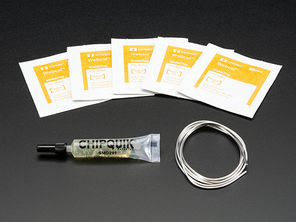
Figure 5-12: Chip Quik SMD Removal Kit
Image courtesy of Adafruit Industries, CC BY-NC-SA 2.0.
How to Solder Simple Surface Mount Devices
Soldering SMDs is a lot different than soldering through-hole parts. We’ll start by soldering a 0805 LED, which doesn’t have any visible leads, but is easily soldered in place. The term 0805 refers to the size—it’s just about 0.08″ by 0.05″ long. It’s small, but not even close to the size of a 0201 component! (See Figure 5-13.) The next step is to make sure you have the component oriented properly. A standard through-hole LED has a long lead and a short lead. The longer lead is the positive (+) lead. SMD manufacturers mark their components’ polarity differently. On an LED, there is typically a marking on it somewhere, or a notch in the plastic that indicates the polarity, but you will need to reference the component’s datasheet to know for certain, since there is a lot of variation between manufacturers.
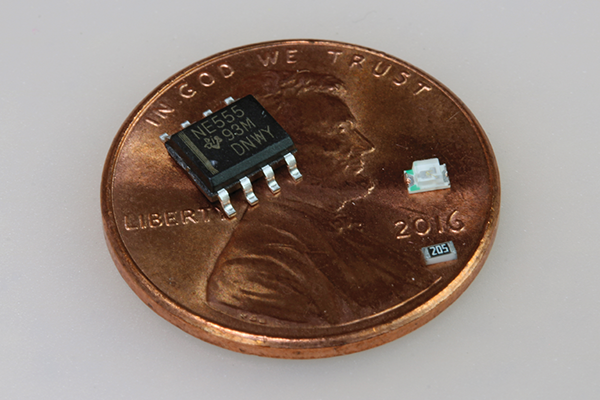
Figure 5-13: The size of SMT components
First, start by wiping the flux pen on the pads of the PCB where you want to solder the component in place. This will help reduce any oxidation and improve the wetting action. Next, make sure your soldering iron is up to temperature and the tip is clean. Then melt a small amount of solder to the tip of your iron and place it on one of the pads where you plan to place the component and hold it there for 1–2 seconds. A small amount of solder should flow off the iron’s tip and onto the pad of the PCB, as shown in Figure 5-14.
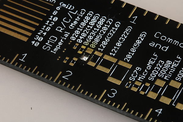
Figure 5-14: Adding solder to one of the pads, after using a flux pen, in preparation for soldering in an SMD LED
Next, place the component on the pre-tinned pad, and heat that connection up with your soldering iron. The solder will flow again and the component will be seated against the PCB. Remove the heat. This will hold the component in place for the next step. (See Figure 5-15.)

Figure 5-15: Soldering the surface-mount component in place
Now that one side is soldered, heat up the other side of the component and pad with your soldering iron. While they’re being heated, add a small amount of solder to the connection point. A little solder goes a long way. It should end up looking similar to a through-hole component in terms of its general appearance, with a nice shiny solder connection that engulfs the end of the component. (See Figure 5-16.) Now, go back and make sure the other side is adequately soldered. If it’s not, you can add additional flux and solder, as needed. In most cases, you won’t have to add any solder, since you only need a small amount to secure SMD components. The last step is to clean up any excess flux with rubbing alcohol. I use prepackaged wipes that are specifically designed for this task.

Figure 5-16: Soldering the surface-mount component in place
How to Solder a Multi-lead SMD
Some SMT uses components with small wire leads, like those pictured in Figure 5-17. To solder this many leads, you could pre-tin the pads on the PCB, but the component may not end up in the proper place once all the solder flows. Fortunately, there is a much easier and more efficient way to make these types of connections.

Figure 5-17: Tacking the IC in place
Start by fluxing all the pads where the component will be soldered. Next, place the component on the PCB, aligning the pads to the pins. Make sure the component is oriented correctly; if you aren’t sure, check the instructions or datasheet. Now, add a small amount of solder to the clean tip of your iron. Next, while holding the SMD in place, heat one of the legs of the component. Finally, remove the heat when the solder flows onto and under the leg of the SMD, which should only take 1–2 seconds, depending on the temperature of your iron. The component is now tacked into place, and you’re ready for the next step.
Now that the component is tacked in place, make sure it’s aligned properly with all the pads on the PCB. If not, you can add some flux, heat up the tacked pin, and carefully move the component into place.
Now, starting on a side of the SMD that is not tacked in place, apply solder and iron to one pin. As soon as the solder starts to melt, drag the tip and the solder across all the pins on that side of the component (as seen in Figure 5-18). This is called the drag technique for obvious reasons. Don’t worry if there are solder bridges, since there will most likely be a few. It’s more important to have enough solder and proper wetting of the pads and leads. Repeat this process on all sides of the SMD.

Figure 5-18: Soldering ICs with the drag technique
You will inevitably have excess solder on the leads of the components, and possibly a bridge or two. (See Figure 5-19.) The number of solder bridges you have greatly depends on how many leads there are and how closely they are spaced on the component. It may be just one or two of the leads, or it could be all of them. Don’t panic; it’s totally OK and easy to fix. In fact, it’s better to have a little excess solder in this situation. You want to make sure there is a good wetting action on all the leads.
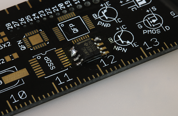
Figure 5-19: Excess solder on the component, forming a solder bridge
To fix any solder bridges and remove excess solder from the components, you will use some copper solder braid. Place the braid over all the leads on one side of the component while heating it from above with your iron. This will wick up excess solder, leaving a nice clean connection. You can see on the left of Figure 5-20 that the leads have all been cleaned up. On the right, I’m in the middle of wicking up the excess. It only takes a few seconds of heat to remove the excess solder, and it makes the connections look great and, most important, work perfectly.

Figure 5-20: Excess solder being wicked up with copper solder braid
That’s it! Simple; and you can see in Figure 5-21 that it looks like a professional fabrication house used their fancy equipment to solder that SMD in place. I wish I had known years ago just how easy it is to integrate SMT into my projects.

Figure 5-21: Finished SMD soldered in place
When Something Goes Wrong—Fixing and Removing Components
You might be asking yourself, “What happens if I make a mistake? It’s hard enough to solder the components in place. How can I remove multi-lead SMD components with just a soldering iron?” It’s not as difficult as it sounds, and you don’t need a hot air rework station—just a little Chip Quik and a regular soldering iron. Chip Quik uses a special metal alloy that will bond to your solder and keep it flowing longer (see Figure 5-22). This will allow you to heat up all the leads with just a standard iron, and then pluck the component away from the pad with tweezers. Start by applying the Chip Quik flux to all the leads of the component, as shown in Figure 5-22. Next, let the special metal alloy flow onto all the leads you want to remove, as pictured in Figure 5-23. Next, go back and heat all the leads again with your iron. Remember: the Chip Quik alloy will stay molten for a longer period of time than standard solder. Now, quickly grab the component with tweezers and remove it from the PCB. (See Figure 5-24.)

Figure 5-22: Chip Quik flux being applied to the leads of the component that needs to be removed
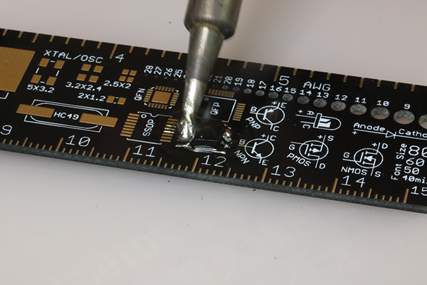
Figure 5-23: Chip Quik alloy being used on a PCB to remove a component
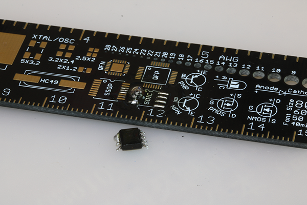
Figure 5-24: The component successfully removed
The last step is to clean up the remaining solder with some copper solder braid, and wipe down the PCB with the alcohol pad supplied in the Chip Quik kit. This is a great solution for removing components without the need for a hot air rework station.
Summary
We have covered the absolute basics of soldering surface-mount components, but there is so much more to cover, like stencils, reflow ovens, and more. It’s enough for another whole book—or even two! Hopefully, this book got you started in the right direction and made you want to learn more. Happy soldering!