4
Troubleshooting and Fixing Mistakes
The process of soldering is fairly simple, but a few things can and will go wrong. Fortunately, most of these issues are avoided or easily fixed. After some practice, you will be able to solder hundreds of connections without any issues whatsoever.
Common Mistakes
In this section, we'll look at some of the most common mistakes that are made by people learning to solder, how to recognize them, and solutions for fixing them. Even experts sometimes make these mistakes, so don't feel bad if you do, too. Everything gets better with practice!
Cold Joint
The most common mistake that I have seen people make is not heating components equally, or enough, which creates a cold joint. This happens when the component lead is not entirely heated by the iron, or the iron is on the lead for too short a time or at too low a temperature, as shown in Figure 4-1. This makes the solder bond to the lead, but not to the joint of the PCB. The same can happen if you heat the copper pad of the PCB more than the lead wire, which results in the pad receiving enough solder, but not the lead. In either case, the wetting action, which forms a proper electrical and mechanical connection, did not occur. You can typically fix this mistake by reheating the joint closer to the side where the solder did not flow and trying to make the connection again. You may need to introduce a little more solder if the joint looks dirty from oxidation.
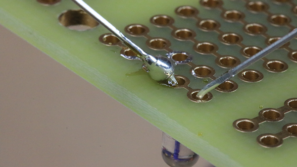
Figure 4-1: An example of a cold solder joint
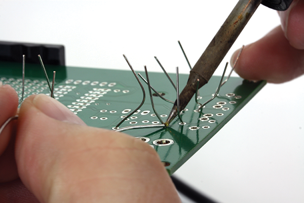
Too Little Solder
Another very common issue is not flowing enough solder into the connection (see Figure 4-2). I see this happen to people when they are nervous about soldering. They think the board will burn if they heat it for too long, so they just feed a little solder in and remove the heat. Although it is true that you can burn the board if too much heat is applied for too long, not adding enough solder makes for a bad mechanical connection. To fix this mistake, simply reheat the joint and introduce some more solder.

Figure 4-2: Too little solder was added to this connection.
Too Much Solder
Too much solder can also be a problem (see Figure 4-3). Although you might get away with this common mistake if it’s only at the joint, it can cause issues. For example, if the solder touches another lead or pad of the PCB, it can short out the leads of the other component. If you flow too much solder in a connection, it’s easily removed with either copper braid or a solder sucker, a technique that is covered later in this chapter.
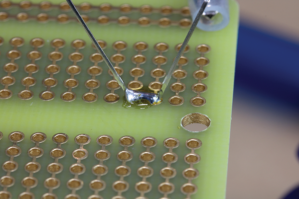
Figure 4-3: Too much solder causing a solder bridge
Too Much Heat
Although it’s more common to apply too little heat at the solder joint, too much heat can be just as much of an issue (see Figure 4-4). It can have a negative effect on the integrity of the connection, and it can also melt or burn the PCB, both of which are not good! In some situations, the copper pad of the PCB can be destroyed beyond repair, although this is rare. Lastly, too much heat can damage the component being soldered, especially if it’s an integrated circuit (IC) or other heat-sensitive component. Too much heat can be difficult to fix, so prevention is the best course of action—use less heat. It’s much easier to fix a cold joint by reflowing the solder and making a perfect connection.
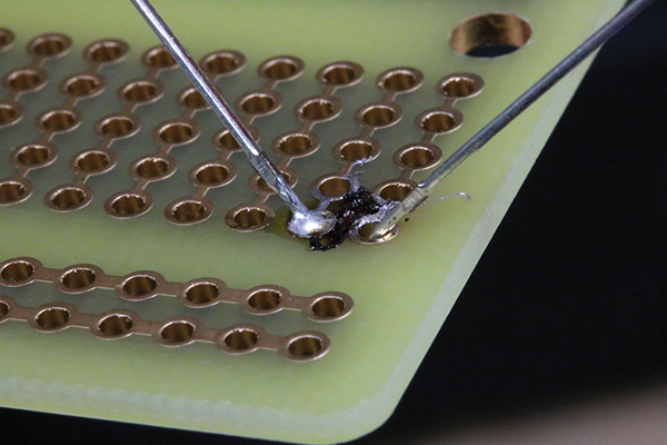
Figure 4-4: Too much heat at the connection
Too Much Movement
You need to make sure the parts you are working on are held securely, and this is why you need a third hand or PCB vise. If the components move while the solder is hot, you will create a joint that looks rough, as seen on the left of Figure 4-5. This is commonly referred to as a disturbed joint. This may not make a reliable electrical connection, and it can also make for a more brittle joint, which could lead to future mechanical failure. You can usually fix this type of poor connection by reflowing the solder at the joint, while making sure nothing moves. Again, you may need to introduce a little extra flux or solder to make sure the solder flows and a proper wetting action occurs.
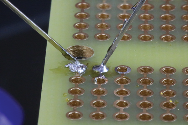
Figure 4-5: Joint disturbed when soldering
Wire Lead Soldered to PCB
Sometimes when you’re adding a component to the PCB, you can bend the leads too far down and inadvertently solder the wire lead to the PCB (as shown in Figure 4-6). This will cause shorts and is generally a bad thing! You can easily avoid this issue by not bending the leads more than 45° from the connection point. To fix the problem, you are going to need to remove the solder from the entire connection and try again. Don’t worry: removing solder isn’t too difficult! And that’s exactly what I want to talk about next.

Figure 4-6: A wire lead lying flat and soldered to the PCB—not good!
As I mentioned earlier, the most common fix for many mistakes is simply to remove the solder and start over. Fortunately, removing solder is not difficult, and there are several ways of doing it. We’ll examine a few of them in the next section, and learn about some helpful tools.
Different Ways to Remove Solder
As I’ve mentioned throughout this chapter, the solution to several of the most common soldering problems is to remove solder. Depending on the issue, there are several different ways to go about it.
The easiest and fastest way to fix a solder bridge (see Figure 4-7) in a connection is to simply reheat the joint and wick some of it away. To do this, first make sure your iron is hot, and wipe the tip on a sponge to make sure it is clean of any excess. Next, reflow the joint and pull the tip of the iron away. (See Figure 4-8.) Wipe the solder off the tip by dabbing it on the sponge again. You can repeat this process a few times to see if it removes enough of the excess solder, but be careful not to overheat the solder or the PCB. When a solder bridge forms between two pads, most of the time a quick reheat solves the problem.

Figure 4-7: A solder bridge

Figure 4-8: A solder bridge being repaired
When you have way too much solder and the simple reheat-and-wipe technique won’t work, or if you have several solder bridges to deal with, the use of copper braid will easily solve the problem. Start by making sure your iron is clean and up to temperature. Next, place the copper braid on top of the solder that you want to remove. Place your iron on top of the copper braid and you will see the solder wick into the braid. (See Figure 4-9.) Once the braid looks saturated with solder, remove the iron and the braid at the same time. The key point here is at the same time. This ensures the still-molten solder will be removed along with the copper braid. This is a good solution for removing excess solder, but if you need to remove all the solder so you can remove a component, you need to use a solder sucker, and that’s what we will look at next.

Figure 4-9: Multiple solder bridges on top and another set being fixed with copper braid below
A solder sucker is a small, manual vacuum pump that will safely remove molten solder. Using a solder sucker is easy, but it requires excellent timing. Get the solder sucker ready to remove the solder by pressing down on the plunger. Next, with your soldering iron in one hand and the solder sucker in the other hand, heat the solder connection you would like to remove (see Figure 4-10). Now remove the iron, immediately place the solder sucker’s tip on the solder connection, and hit the button. This creates a vacuum that sucks up the molten solder. Last, press down on the plunger and eject the cold solder into a proper container for disposing. Repeat, as necessary, to remove all the solder.
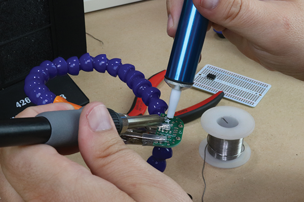
Figure 4-10: Component that needs the solder removed with a solder sucker
The electric solder sucker, shown in Figure 4-11, is a new tool I found while doing research for this book, and after using it, I instantly fell in love with it as a teaching tool. Just like a standard solder sucker, you place the tip over the area that needs the solder removed. But this tool has an integrated heater, so you don’t need to make the quick—and sometimes tricky—switch from heating with the iron to using the solder sucker. I don’t think everyone needs this tool, since a standard solder sucker works fine. However, for a lab with multiple users, especially in a lab used to teach soldering, this can be a lifesaver (and a PCB saver!). For day-to-day use, I’ll stick with a standard nonelectric version, but when I am teaching a group of students, I will certainly bring this tool with me to use for the inevitable mistakes.
Figure 4-11: Electric solder sucker
After you use a solder sucker, you must eject the spent solder from the device. But where does that solder go? Typically, I see people eject it onto their work bench or, worse, the floor. If these little bits of solder get on your PCB, they can cause shorts. Worse, if the bits are lead-based they can be stepped on and tracked all over the place, causing an environmental hazard. Do yourself a favor and make a proper disposal system for your solder sucker—a solder sucker spittoon. (See Figure 4-12.) It’s one of the easiest DIY projects for your electronics work bench. Simply find any flexible container and cut a small circle in the top. Once you use the solder sucker, place the tip of it through the opening in the top of the container and eject the spent solder. If you are using an electric solder sucker, though, make sure you cut a large enough opening so the heated tip does not melt the plastic.

Figure 4-12: Make a solder sucker spittoon for safe disposal of your spent solder.
Repairing Lifted Pads
Although it’s rare, you may eventually need to repair a lifted pad on a PCB. This is typically caused by significantly overheating the PCB, but I have also seen this occur on poor-quality PCBs. If you purchase your parts from a reputable shop, it’s almost never an issue. Poor-quality boards are usually very inexpensive and purchased from no-name online stores. I guess you get what you pay for.
To be totally honest, it was unbelievably difficult for me to make a solder pad lift on the high-quality PCBs I have in my studio. However, after heating and abusing the solder connection on the PCB for more than 30 seconds, which is about 26 seconds too long, I did manage to get a slightly lifted pad. It is amazing how difficult it is to make this type of mistake. It’s a testament to buying your PCBs from well-known sources.
There are cases where you won’t be able to fix the lifted pad, and sometimes a lifted pad won’t affect the final project. However, most of the time you are going to want to try to fix the problem. Once you notice the pad is lifted, stop! Next, remove the solder using a solder sucker. Now, trim the component lead long enough to hold the pad in place, but not so long that it causes a short circuit with any other components. Next, bend the cut lead down against the PCB at a 90° angle and it will hold the pad in place. Last, solder the connection. In Figure 4-13, you can see that I bent the wire lead to the right, where there weren’t any other components, and soldered it into place. This should fix the lifted pad. If it doesn’t, you may be able to bypass the connection with a new piece of wire, or in the worst case you might have to start over with a new PCB. Fortunately, a lifted pad is rare, and destroying a PCB beyond repair is exceptionally rare, especially after you have a few solder connections under your belt.
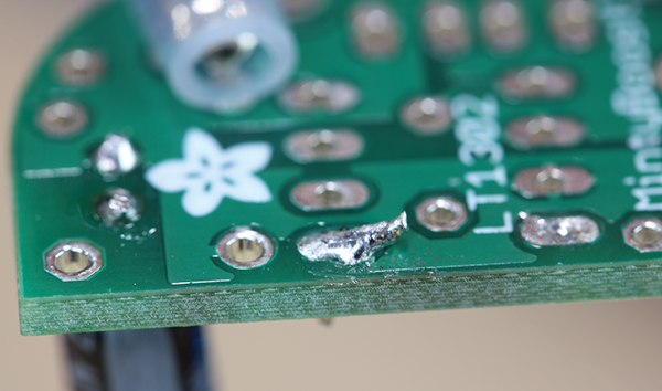
Figure 4-13: Repair to a pad that was damaged by extreme overheating of the PCB