
Brief Overview of Carbon and Its Cousins
Abstract
This chapter gives an overview of natural carbon and graphite and establishing some similarities with the properties of carbonaceous nanomaterials. A description of carbon's electronic properties and atomic structure is reviewed, including s- and p-orbitals, bonds, and hybridization. The discussion puts particular emphasis on the edge sites of graphite (primarily armchair and zigzag) and surfaces, and the dangling bonds associated with the edge sites relating their importance in applications.
Keywords
Carbon; edge sites; graphite; electronic structure; surface area; sp2 orbitals; sp3 orbitals; zigzag faces; armchair faces; dangling bonds; graphite oxidation
1.1 Electronic Structure
Carbon is an exceptional element with remarkable properties, but most people forget the versatility of this key component of life itself. Reviewing these basic properties will help you appreciate our discussions later. Those of you who remember their high school chemistry may skip this section. Essential to all chemical reactions is the bonding mechanism and electronic structure of the reactants. Normally, chemical bonding takes place between similar structures. Two s-orbitals or two similar p-orbitals bind together in an antibonding and bonding manner. For many of the carbon atoms, the binding of the same kind of molecular orbitals is not the case. In fact they form bonds by mixing (hybridizing) different orbitals, namely s- and p-orbitals. This versatility of carbon–carbon bonding creates a wealth of extraordinary physical properties.
A carbon atom contains six electrons which occupy the following electron configuration: (1s)2(2s)2(2p)2. In the ground state there are two unpaired electrons in the outer shell, seemingly possessing the ability to bind only two additional electrons, but, as we very well know, a four electron binding behavior is observed. The reason is that one electron from the 2s- state can easily be excited to the 2p- state due to the very small energy difference; this can result in a mixed state formed out of one s- orbital and three p-orbitals, namely px, py, and pz in which case four new hybrid orbitals can be formed and termed sp3 orbitals (see Fig. 1.1). This combination of the hybrid orbitals produces a tetrahedral structure we know as a diamond. Due to the three-dimensional sp3 structure, the binding strength between neighboring carbon atoms is equal for each atom and is very strong.
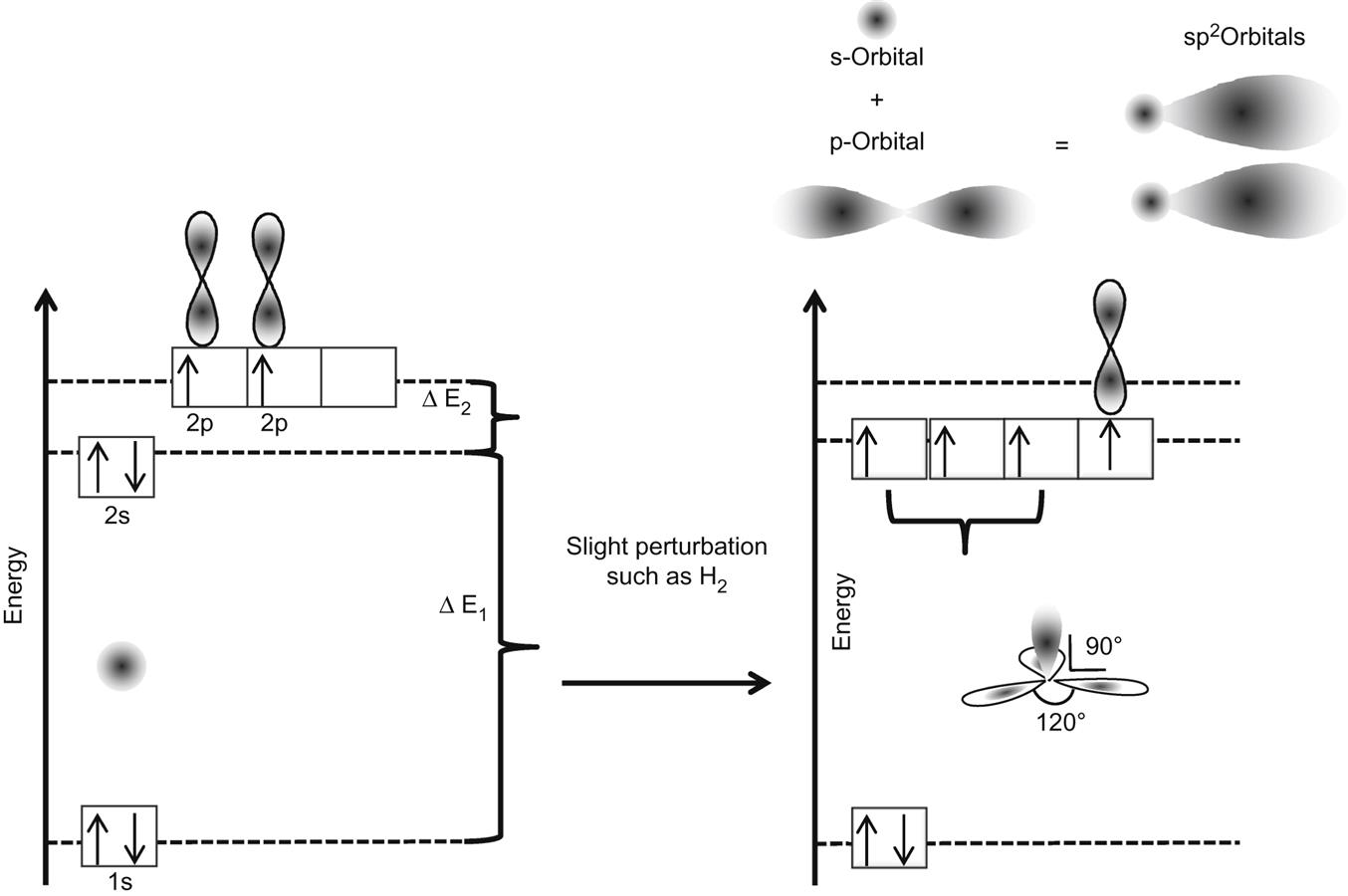
When one s-orbital and only two p-orbitals hybridize, they form a planar assembly with a characteristic angle of 120° between the hybrid orbitals. The hybridized orbitals form σ-bonds in the planar direction. The additional p-orbital exists perpendicular to the sp2-hybrid orbitals and forms π-bonds. In graphite, this planar structure is formed between 6 carbon atoms and the p-orbitals form π-bonds which create a delocalized state for all the electrons. Such a delocalized state in graphite can be thought of as a donut-shaped electron density above the planar surface.
The in-plane σ-bonds in sp2-hybridized carbon are stiff against longitudinal forces but soft for angular deformations. This flexibility opens the door for the wide range of stable graphitic nanostructures. One major property is in electron transfer. The electronic properties of sp2-hybridized carbon materials are generally determined by the delocalized π-orbital. Unlike the strongly bonding σ-orbitals, the π-orbitals are generally close to the Fermi energy. The Fermi energy is the difference between the highest and the lowest occupied orbitals of isolated particles at absolute zero temperature (hence a measurement of the “total” chemical potential of the electron), leading to the in-plane conducting or semiconducting properties of graphitic materials. Many electronic applications can benefit from this property. To study the orbitals, we need to imagine a single sheet of planar carbon material that is two dimensional in nature, and (now famously) known as graphene. In a single, flat graphene sheet, the in-plane sp2 orbitals are symmetrical and the π-orbitals are asymmetrical and delocalized. This discourages any matrix elements that can couple both types of orbitals. These two groups of orbitals form two independent sets of bands: (1) the σ-bands, formed by the sp2-hybridized orbitals, which are responsible for the structure. These lie far below and above the Fermi energy, so they have negligible influence on the electronic properties at energies relevant for electronic transport. (2) The π-bands, formed by the atomic π-orbitals, are half filled, right around the Fermi energy, and are responsible for transport and other electronic properties at low energy.
Therefore, on a finite dimension, at the end of this plane, the edges of the perfect hexagon structure end up with incomplete σ-bonds, commonly referred to as “dangling bonds.” These dangling bonds impart important qualities to the graphene plane, which are very relevant to the applications we are about to explore. I have therefore dedicated a separate section to explain these states in detail next.
To summarize, graphite is a multi layered planar structure. Each individual layer is called graphene and is formed by three hybridized sp2 orbitals. These orbitals form σ-bonds, in the planar direction, creating a sheet that is very stable longitudinally. The p-orbital electron, which is not hybridized exists in a direction perpendicular to the plane and is delocalized with the other p-orbital electrons of the five neighbor carbon atoms. This property is responsible for a very important quality, desired by electronic transport applications. A singular sheet in graphite is called graphene and consists of carbon atoms attached by σ-bonds and delocalized p-orbitals. When an infinite graphene sheet is theoretically cut, the edges from the planar σ-bonds are left with dangling bonds.
1.2 The Edge Sites
The importance of an edge to a graphene sheet parallels that of a surface to a crystal. As is common knowledge, the lateral dimension and plane of the graphene sheet is being pursued for future electronic and thermal transfer applications. Obtaining such sheets in practical dimensions without any surface defects is providing scientists with unprecedented opportunities in physics and chemistry research. But pristine graphene sheets with dimensions even in the single digit μM size, have proven to be far more difficult to synthesize than initially assumed. Outside of prospective applications that promise to enhance electrical conductivity, semiconductor behavior, and thermal conductivity (which, currently are stuck in the (inability to produce in larger) size conundrum indefinitely, very few applications are candidates for this expensive material. Whether you want to make a plastic composite, a higher performance catalyst, a better lubricant, a better drilling fluid, etc., the most important requirement turns out to be, not single or few layer “graphene”, but the ability of the nanomaterial flake(s) to either react or be miscible in the material to be enhanced. Not surprisingly, then, the graphene applications being advertised, as near term are primarily those that would result from the unique properties of the edge sites, not those of a single (or few)-layer graphene. No experimental data within these large scale applications to my knowledge suggests that specifically single-layer or few-layer [6–10] graphene materials are required to achieve the results reported by researchers using expensive graphene. Even if there was such a claim, my contention is that graphitic nanofibers (GN) will be able to achieve a high percentage of those enhancements, resulting in better economic returns. Since pristine graphene sheets of usable size are not within my definition of “practical” (yet), I will focus on the many applications made possible by these edge states. Therefore a detailed discussion about energy levels, bonding abilities, and bond strengths of these edge sites is crucial in my endeavor to demonstrate the versatility of GN.
 100
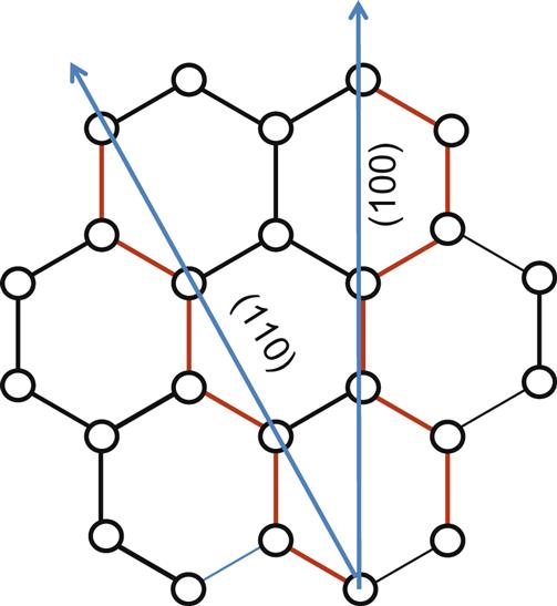
100 110 direction cuts across graphene plane to form zigzag and armchair faces. See also Fig. 1.3. The exposed electrons and sites are in red (dark grey in print versions).
So let us imagine cutting through an infinite graphene sheet. We first end up first breaking the (C![]() C) σ-bonds and then obtaining two semi-infinite graphene sheets, each with a one-dimensional edge. Along the cut, the edges will be exposed. The cut also introduces a boundary at the edge to the previously fully delocalized π-electron system. Imagine a hexagonal plate, with a donut suspended above. If cut, half the plate as well as half of the donut will disappear. The edges of the plate will have no carbons to bond with, and similarly, neither will the donut.
C) σ-bonds and then obtaining two semi-infinite graphene sheets, each with a one-dimensional edge. Along the cut, the edges will be exposed. The cut also introduces a boundary at the edge to the previously fully delocalized π-electron system. Imagine a hexagonal plate, with a donut suspended above. If cut, half the plate as well as half of the donut will disappear. The edges of the plate will have no carbons to bond with, and similarly, neither will the donut.
I will give a brief and simplified view of quantum mechanics to explain a reference following. The geometry of the edge sites makes a major difference in the π-electron structure at the edge. In quantum mechanics, an electron mass can be represented as (short bursts of) waves, and the complex formula for the resulting plot (“shape”) is called the wave function. The location of the electron via probabilistic calculations can be estimated based on this wave function. At equilibrium, the band will be represented by a flat line representing the Fermi level. The energies of the bands are calculated in what is called “k-space” or sometimes called “momentum space”. This is an abstract space intimately related to the real or position space hence a k vector is then conveniently used to calculate the energies of the extended orbitals in crystalline solids. Again, this definition is only to give you some background of the techniques used in the next reference to verify the energy difference between the two exposed faces. A detailed discussion is out of the scope of this book. Nakada et al. [11] showed that the zigzag edge in a graphene sheet has a flat band near the Fermi level for the k vector between 2π/3 and π. For k=π, the wavefunction becomes completely localized at the edge sites. This flat-band feature and its corresponding localized state are unique to the zigzag edge (they are completely absent from the armchair edge).
Edge or surface energies both quantify the disruption of interatomic bonds. If all dangling bonds were equal in graphene, the edge energy proportional to their density would be higher for the more tightly packed armchair than for the less dense zigzag, by exactly a factor of 2/√3=1.15. In Fig. 1.4 [12], however, this very difference in density makes armchair sites form triple bonds and thus lowering their energy relative to the zigzag edges.


Fujii and Enoki [13] also write that armchair edges are energetically stable due to the aromatic stability, whereas less-aromatic zigzag edges are unstable. The nonbonding edge state of π-electrons is confirmed to exist in the zigzag edges, in spite of the absence of such a state in armchair edges. In a finite-length zigzag edge embedded between armchair edges, the electron confinement effect is observed in the edge state.
Kobayashi [14] predicted the existence of such a flat band and localized state on a zigzag-edged vicinal graphite surface. Highly oriented pyrolytic graphite (HOPG) surfaces have also shown the existence of the zigzag edge, and the localized state at the zigzag edge was confirmed by scanning tunneling spectroscopy (STS), which essentially takes images at the atomic level.
Now, if we imagine cutting the semi-infinite graphene sheet again, and in the same direction as the first cut, parallel to the edge, we would generate what is now known as a graphene ribbon with two zigzag edges. If the ribbon width falls within the nanometer range (zigzag graphene nanoribbons, GNR), the two edges would interact with each other, possibly forming a single-walled carbon nanotube.
Although H-free carbene-like zigzag edges [15] and H-free dangling σ-bond zigzag edges [16] have also been proposed to explain magnetism in carbon materials, it seems unlikely that those edge sites can survive under ambient conditions (room temperature in air) due to their high chemical reactivity. The zigzag state observed in air by STS at room temperature has been attributed to zigzag edges with saturated σ-bonds [17].
To date, almost all theoretical and computational studies of graphene zigzag edges have focused on the physical aspects, such as electronic structures and magnetic properties. For example, the theoretical studies calculating weak ferromagnetism along one edge, and antiferromagnetism between two edges (one edge spin-up, the other spin-down) on a zigzag-edged graphene nanoribbon (ZGNR) [18].
From a practical perspective, the localized state at the zigzag edge offers the most useful electronic properties to help us achieve our goal. Due to the nonbonding character of the localized state and the closeness of the flat band to the Fermi level, the zigzag edge sites should theoretically be similar to radicals. Jiang et al. [19] have shown calculations on GNR edges on how the edges distribute π-electrons and how these π-electrons contribute to reactions by external chemical stimuli. To show that ZGNRs are indeed unique (with respect to their useful surface area being the edge sites), they compared ZGNRs with a planar graphene sheet, nanotubes, and an armchair edge, for their reactivity with atomic hydrogen. They have shown that spin-polarized π-electrons are localized on the zigzag carbon atoms, which, from a chemistry viewpoint, prompts us to think of them as a “partial radical.” That is, these ZGNRs have unpaired π-electrons distributed mainly on the two edges, but on average each edge carbon atom has only 0.14 electrons. Due to the partial radical character, these edge carbon atoms offer special chemical reactivity, compared to planar carbon atoms, armchair carbon atoms, or nanotube carbon atoms. In the reaction of the zigzag edge with a hydrogen atom, the bond dissociation energy (BDE) was calculated for the newly formed C![]() H bond in which C was an edge carbon [20]. The BDE changed only slightly for widths of N=4–6. Anderson [20] also observed a ratio of zigzag faces to armchair was relatively consistent at 1.7:1 in platelet type GN. With this characterization, GN start looking even more practical for producing consistency in performance, capacities for functional groups, reactive groups, etc.
H bond in which C was an edge carbon [20]. The BDE changed only slightly for widths of N=4–6. Anderson [20] also observed a ratio of zigzag faces to armchair was relatively consistent at 1.7:1 in platelet type GN. With this characterization, GN start looking even more practical for producing consistency in performance, capacities for functional groups, reactive groups, etc.
Comparing with other C(sp3)-H BDEs (4.553 eV for C2H5-H and 4.315 eV for cyclo-C6H11-H) [21], the CH bond formed at the zigzag edge had a strength of ~60% of the C![]() H bond between a molecular carbon radical and H, again indicating a “partial radical” concept. The disparity of a partial charge of ~0.14 eV but the edge C
H bond between a molecular carbon radical and H, again indicating a “partial radical” concept. The disparity of a partial charge of ~0.14 eV but the edge C![]() H bond generating a strength of ~60% of a common C
H bond generating a strength of ~60% of a common C![]() H bond is explained by another very important aspect of the chemical reactivity at the zigzag edges. Although the localized state at the zigzag edge offers only a partial amount of the π-electron density on a per edge carbon basis, remember these partial electrons are not confined to those edge carbons, but can act collectively when interacting with another radical [18]. So here the “localization” (or “localized” state) at the edge sites is meant to be with respect to the inner sites. Two pieces of evidence support the idea that zigzag edge π-electrons can respond collectively to an attacking radical. First, after the formation of a C
H bond is explained by another very important aspect of the chemical reactivity at the zigzag edges. Although the localized state at the zigzag edge offers only a partial amount of the π-electron density on a per edge carbon basis, remember these partial electrons are not confined to those edge carbons, but can act collectively when interacting with another radical [18]. So here the “localization” (or “localized” state) at the edge sites is meant to be with respect to the inner sites. Two pieces of evidence support the idea that zigzag edge π-electrons can respond collectively to an attacking radical. First, after the formation of a C![]() H bond at an edge coverage of 1/6, the local magnetic moments on the intact carbon atoms on the same edge greatly decrease. In other words the electronic states at the zigzag edge act together when a C
H bond at an edge coverage of 1/6, the local magnetic moments on the intact carbon atoms on the same edge greatly decrease. In other words the electronic states at the zigzag edge act together when a C![]() H bond is formed at one of the edge carbon sites, even though the electron density is distributed evenly at the edge carbon atoms before the bonding.
H bond is formed at one of the edge carbon sites, even though the electron density is distributed evenly at the edge carbon atoms before the bonding.
The second piece of evidence is that the BDE is found to decrease with the edge coverage because there are fewer edge electrons available on a basis of per C![]() H bond formed when the coverage increases. Like the C
H bond formed when the coverage increases. Like the C![]() H bond, the C
H bond, the C![]() OH and C
OH and C![]() CH3 bonds formed at the edge have a BDE of 50–70% of C2H5
CH3 bonds formed at the edge have a BDE of 50–70% of C2H5![]() OH and C2H5
OH and C2H5![]() CH3 bonds [18]. For the halogens, the BDE of edge-X decreases from fluorine to iodine and follows the same trend as that of C2H5-X. This trend is attributed to the decreasing electronegativity between fluorine and iodine. Fluorine being the most electronegative has the greatest BDE. Moreover, one notes that the BDE ratio of edge-X to C2H5-X increases dramatically from chlorine to fluorine, indicating the extraordinary ability of fluorine to pull electrons from the zigzag edges.
CH3 bonds [18]. For the halogens, the BDE of edge-X decreases from fluorine to iodine and follows the same trend as that of C2H5-X. This trend is attributed to the decreasing electronegativity between fluorine and iodine. Fluorine being the most electronegative has the greatest BDE. Moreover, one notes that the BDE ratio of edge-X to C2H5-X increases dramatically from chlorine to fluorine, indicating the extraordinary ability of fluorine to pull electrons from the zigzag edges.
By detailed analysis and calculations, it has been shown [18–20] that the zigzag-edged GNR has a significantly higher C![]() H BDE than the armchair-edged GNR, nanotubes, or a graphene sheet. ZGNR’s unique electronic structure has a substantial peak near the Fermi level, which directly leads to its stronger bonding to hydrogen.
H BDE than the armchair-edged GNR, nanotubes, or a graphene sheet. ZGNR’s unique electronic structure has a substantial peak near the Fermi level, which directly leads to its stronger bonding to hydrogen.
These collective research and experimental findings support the hypothesis that the chemical reactivity seen for the π-electrons of ZGNRs contribute to the chemical behaviors of carbon or graphitic materials which essentially have only edge sites. The implication here is that a uniform structure at the nanoscale with consistent platelet dimensions and possibly predictable bulk properties such as average zigzag to armchair face ratios could give quantifiable data to design and implement applications.
Finally, for those of you who like derivations in a scientifc discussion, Rotkin et al. [22] have proposed a four-parameter model toward a unified approach to define the energetics of the graphene edge regions. It has been shown [23, 24] that there are four approximately independent energy components, as well as a large constant contribution, which is the chemical potential of the carbon atom in a flat graphene. They counted the energy from the “zero level” of the infinite graphene sheet and omitted the large (~7 eV/atom) constant to arrive at the following, for the four contributions:
(1.1)
• Nd is the number of defects (primarily pentagons and heptagons) in the hexagonal lattice of graphite. It equals zero for the perfect graphite lattice.
• εd is the defect energy and consists, in general, of two parts: the dislocation core energy and the elastic energy accumulated in the distorted lattice around the defect. The latter is accounted for separately in the second term. This term is parameterized with the characteristic elastic energy:
• Ec (the elastic tensor, in general case) resembling the flexural rigidity of a thin shell [25–27]
• Any external stress should be included explicitly, but was not considered in the Rotkin model.
• K (R1, R2) is the tensor of curvature, and, with R1 and R2 being the principal radii of the curvature [28] defines the internal strain.
Therefore the whole second term diminishes to zero for the perfectly flat graphite structure. This term collects all elastic contributions and counts all atoms in hexagons, N6, except the ones belonging to the defects or to the system edges. The surface energy (third term) is modeled at the microscopic level by counting the number of dangling bonds, Nb, multiplied by the dangling bond energy, Eb. This characteristic energy can vary with the change in the surface bond population.
The fourth term (van der Waals energy) is roughly proportional to the number of neighbor atoms in the adjacent layers, Ncont. Graphite, its modifications, and other layered crystals are described within the van der Waals theory in respect to the interlayer interaction energy W [15,29, 30–32]. These interaction forces are essentially short ranged, which justifies the use of the simplest approximation of the contact interaction.
The natural graphite flake has a hexagonal shape with the edges in [110] face and symmetry equivalent zigzag directions [16, 33]. The disoriented graphene edge can be considered as a series of kinks along the high symmetry direction (see Fig. 1.5-A).
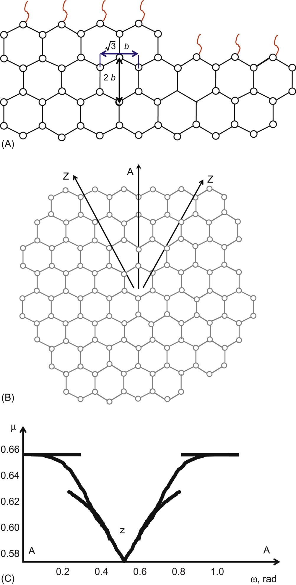
Consequently, the surface energy may be calculated based on the disorientation angle. Similar to the free energy of 3D crystals [34], it has a cusp around the zigzag direction (minimum of the surface energy) and a parabolic shape around the armchair direction (maximum of the surface energy), which is shown in Fig. 1.5-B. A closed expression for the surface energy of the graphite edge with an arbitrary orientation was presented in Ref. [35]. It is based on the assumption that the local hybridization at the edge does not vary with the edge orientation. An almost free graphite edge is addressed, which may be passivated. The typical energy gain due to one kink creation is approximately equal to the half of the dangling bond energy, Eb/2~1.2 eV. This allows us to imagine the magnitude and the scale of energy needed to form the minimal disorientation of the edge. The formation energy of the disoriented edge is quite large compared to the synthesis temperature and, therefore, only zigzag edges at equilibrium should be considered. To minimize energy level then, a continuum planar flake will accept the circular shape. In reality, the density of bonds along the circular perimeter will oscillate (as shown in Fig. 1.5-C) and will increase its contribution to the total energy given by Eq. (1.1).
1.3 Summary
A crucial factor in our discussion of applications with GN is the availability of large external surface area populated with highly reactive edge sites. I may even sound irritatingly redundant about this characteristic throughout the book, so bear with me. Virtually the entire external available surface area of GN is composed of dangling bonds associated with edge sites. Two types of edge sites exist, armchair and zigzag. The zigzag edges are more reactive to chemical attack. The highly reactive surface area with virtually no basal planes puts GN at an advantage for applications where a reaction must take place between the carbonaceous nanomaterial and a reactant. This could be for functionalization, in situ polymerization, or catalyst support. Other materials, including graphite, with large basal plane surface areas, require harsh oxidation procedures to create defects on the basal planes which resemble the edge sites inherently present in GN. So we can expect processing GN to make them ready for industrial use is therefore minimal.