
8
Hacking with Sensors
Chapters 6, 7, and 8 all overlap somewhat, as many sensors are also modules and both can often be used with an Arduino.
In this chapter, we will look at how to use a range of sensors, whether with a little supporting electronics or as an input to an Arduino, or sometimes both.
How to Detect Noxious Gas
In this section, you will use a methane sensor (Figure 8-1).

FIGURE 8-1 A methane sensor
While they look like they should be expensive, these sensors are really quite low cost. They include a small heater (connected between the two H connections) and a catalytic sensing element whose resistance changes depending on the concentration of methane. Although the project will run on batteries, it will burn through them pretty quickly because these sensors have a heating element that will consume 150 to 200 mA.
The sensing of methane does have lots of sensible scientific and industrial uses. However, we will use this technological know-how for the puerile activity of… detecting farts.
You Will Need
To experiment with this gas sensor, you will need the following items.


* Only required if you want to connect the detector to an Arduino.
The piezo sounder must be of the type that includes its own oscillator circuit and will work at 6V.
The LM311 Comparator
Figure 8-2 shows the schematic diagram for the gas detector.
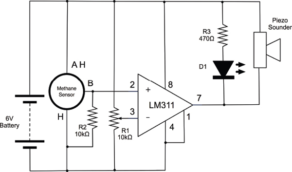
FIGURE 8-2 Schematic diagram for the gas detector
The key to this circuit is the comparator IC (LM311). Comparators, as the name suggests, compare voltages. If the voltage at its “+” connection is greater than the voltage at its “–”
The trimpot supplies a threshold voltage to the negative input of the comparator. To use the gas detector, the trimpot is turned until the LED just goes out. It will come back on if the output from the sensor increases enough to exceed the value at the comparator’s negative input.
The sensor has rather unusual connections. It has six connections, but some of them are doubled up and connected behind the scenes (see Figure 8-1). The H connectors supply a heating element that warms the catalyst layer between A and B. When methane is detected, the resistance between A and B falls. R2 forms a voltage divider with the sensing element. One benefit of the sensor basically being two resistors—one acting as a heater and the other as a sensor—is that the pin connections are reversible.
The sensor leads are thick and at a strange spacing, so they will not fit in breadboard. For this reason, we solder some leads to them (Figure 8-3).

FIGURE 8-3 Attaching leads to the sensor connection, then its output turns on. In this case, that will light the LED and sound a buzzer.
Rather than solder wires to all the leads, we can just solder the following connections:
• A red positive supply lead to all the pins on one side of the sensor (the two A pins and one H connection)
• The resistor R2 between B and the GND side of the heater
• A GND lead to the GND side of the heater (black)
• An output lead to B (yellow)
Breadboard
Figure 8-4 shows the breadboard layout for the gas detector, while Figure 8-5 displays the project itself.

FIGURE 8-4 Breadboard layout for the gas detector

FIGURE 8-5 The gas detector
The breadboard layout is very straightforward, but do make sure that the IC is the correct way around. When it is all assembled, I will leave you to find your own way of testing it. Just a note that breathing on the sensor will also set it off.
Using a Gas Sensor with an Arduino
In soldering the three leads onto the methane sensor, we have also made something that we can easily attach directly to an Arduino (Figure 8-6).

FIGURE 8-6 Using the gas sensor with an Arduino
Connect the positive supply connection from the sensor to 5V on the Arduino, GND on the sensor to GND on the Arduino, and the output of the sensor to A3.
Since this sensor can use up to 200 mA, you must power it from the real 5V and GND connections on the Arduino and not use the trick of powering it from a digital output.
The following sketch (“methane”) prints the readings from the sensor into the Serial Monitor. Again, note that if you breathe on the sensor, the reading will increase.

How to Measure Something’s Color
The TCS3200 is a handy little IC for measuring the color of something. There are several different variations on this chip, but they all work the same way. The chip has a transparent case, and dotting its surface are photodiodes with different color filters over them (red, green, and blue). You can read the relative amounts of each primary color.
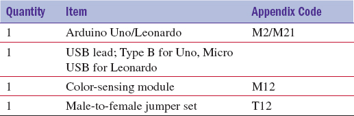
The easiest way to use the chip is to buy a module like the one shown in Figure 8-7.

FIGURE 8-7 A light-sensing module
This module, which cost less than USD 10, also has four white LEDs that illuminate the object whose color you want to measure, as well as convenient header pins.
Table 8-1 shows the connections on the module and their purpose. With the exception of the power to the LEDs, these connections are taken straight from the IC, so any module you find that uses the TCS3200 is likely to have the same connections, even if they are not quite in the same place.

TABLE 8-1 Color-Sensing Module Pinout
The IC does not produce an analog output, but instead varies the frequency of a train of pulses. You choose which color the pulse frequency corresponds to by changing the values on the digital inputs S2 and S3.
You Will Need
Construction
Construction is perhaps too strong a word for it. The module will fit directly into the Arduino (Figure 8-8), facing outward. It will make the following connections:
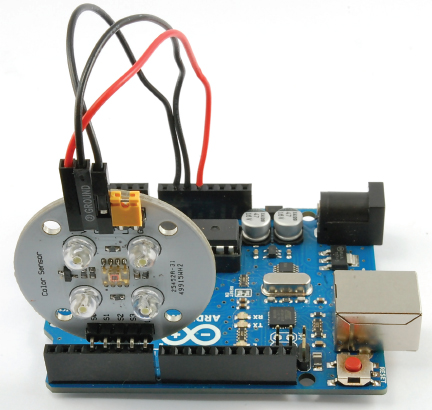
FIGURE 8-8 A light sensor attached to an Arduino
• S0 module to D3 Arduino
• S1 module to D4 Arduino
• S2 module to D5 Arduino
• S3 module to D6 Arduino
• OUT module to D7 Arduino
You will also need three male-to-female jumper leads to connect:
• VCC module to 5V Arduino
• GND module to GND Arduino
• OE module to GND Arduino
Figure 8-9 shows the module sensing colors on a Rubik’s cube.
FIGURE 8-9 Sensing colors on a Rubik’s cube
Software
The sketch “color_sensing” demonstrates the use of this module.

The pins are named according to their function rather than using the module pin names.
The “setup” function sets the appropriate pin modes and then sets both the “prescale” pins that control the output frequency range to HIGH, starts serial communication, and then displays a welcome message.

The “loop” function reads the three different colors (more on that later) and displays a message depending on the dominant color. Note that the lower the value, the brighter that particular color.


Each of the functions—“readRed”, “readGreen”, “readBlue”, and “readWhite”—just call a function “readColor” with the appropriate values for S2 and S3.
The function “readColor” first sets the appropriate pins for the color and records a start time in the variable “start”. It then waits for 1000 pulses to happen. Afterward, it returns the difference between the current time and the start time.

Although not actually used, there is also a function in the sketch that writes the color values to the Serial Monitor.


How to Detect Vibration
Piezo vibration sensors, like the one from SparkFun shown in Figure 8-10, are very easy to use with an Arduino.

FIGURE 8-10 A piezo vibration sensor
The sensors are a thin strip of piezoelectric material with a rivet in the end acting as a weight. When there is a vibration, the weight moves, stressing the piezo material that produces a spike in voltage. Measured with the right test equipment, this spike can be as high as 80V. However, because we are going to connect it to an analog input on an Arduino, the resistance of that input will be sufficient to damp the voltage to a level that will not harm our Arduino.
You Will Need
To detect vibration with your piezo sensor, you will need the following items.

Construction
The piezo sensor is another very Arduino-friendly sensor. It can be just plugged into the Arduino sockets. In this case, it is plugged into pins A0 and A1. A0 will be set to an output LOW and used to provide the ground connection to the sensor (Figure 8-11). Note that the module is marked with a “+” on one side. Connect this side to “A1”.

FIGURE 8-11 Sensing vibration with an Arduino
The LED is joined to a resistor as described back in Chapter 6. This can then be plugged into sockets 8 and GND on the Arduino, with the positive connection of the LED connected to 8.
Software
The software that follows uses the technique of calibrating itself as it starts, to get the “no vibration” reading from the sensor. It then waits until the sensor reading exceeds the threshold set, at which point it lights the LED. Pressing the Arduino “reset” button will cause the sensor to detect movement again.

After defining the pins to use, we then define two variables. The variable “normalReading” is used during calibration (more on that in a minute), and the variable “threshold” should be set to the amount that the analog reading is allowed to exceed “normalReading” by before the LED is turned on.
The “setup” function sets the appropriate pin modes and then calls the “calibrate” function to find the reading for the sensor when there is no vibration.

The “loop” function simply takes a reading and checks to see if it has exceeded the threshold. If it has, it turns the LED on.

To calibrate the sensor, 100 readings are made with a one-millisecond delay between each reading, and the average is returned. A variable of type “long” is used to hold the total, as this number may be too big to fit in the usual “int” type.

How to Measure Temperature
A number of different sensor ICs are designed for measuring temperature. Perhaps the simplest to use is the TMP36 (Figure 8-12).

FIGURE 8-12 The TMP36
You can experiment with the sensor, just printing the temperature to the Serial Monitor, or you can combine the sensor with the relay module we made in Chapter 6.
You Will Need
To use this temperature measurement IC, you will need the following items.

Construction
The TMP36 has just three pins, two for the power supply and one analog output. The power supply needs to be between 2.7V and 5.5V, making it ideal for use with the 5V of an Arduino. In fact, we can supply the power to it through digital outputs and just plug the whole chip into three pins on the analog connector of the Arduino (Figure 8-13).
FIGURE 8-13 The TMP36 attached to an Arduino
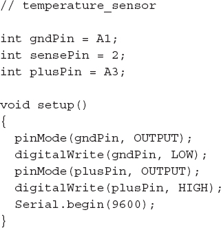
Software
The sketch (“temperature_sensor”) follows what should now be a fairly familiar pattern. The pins are defined, and then in the “setup” function the output pins that provide power to the sensor are set to LOW for GND and HIGH for the positive supply.
The main loop reads the value from the analog input and then does a bit of arithmetic to calculate the actual temperature.
First, the voltage at the analog input is calculated. This will be the raw value (between 0 and 1023) divided by 205. It is divided by 205 because a span of 1024 values occupies 5V, or 1024 / 5 = 205 per volt.
The TMP36 outputs a voltage from which the temperature in degrees C can be calculated from the equation:
tempC = 100.0 * volts – 50
For good measure, the sketch also converts this into degrees F and prints both out to the Serial Monitor.

How to Use an Accelerometer
Tiny accelerometer modules (Figure 8-14) are now available at low cost. The two models shown are very similar, both being 5V compatible and providing analog outputs for each axis. The one on the left is from Freetronics (www.freetronics.com/am3x) and the one on the right is from Adafruit (www.adafruit.com/products/163).

FIGURE 8-14 Accelerometer modules
These modules are three axis accelerometers that measure the force applied to a tiny weight inside the chip. Two of the dimensions, X and Y are parallel to the modules PCB. The third dimension (Z) is at 90 degrees to the module’s surface. There will normally be a constant force acting on this dimension due to gravity. So if you tip the module, the effect of gravity starts to increase on the dimension in which you tip it (see Figure 8-15).

FIGURE 8-15 The effect of gravity on the accelerometer
As a vehicle to test one of these accelerometers, we are going to build an electronic version of the children’s game of egg and spoon. The idea behind this is to use the accelerometer to detect the level of tilt of the “spoon” and flash an LED when it starts to be in danger of losing the egg. A buzzer sounds when the level of tilt is extreme enough for the egg to have fallen off (Figure 8-16).

FIGURE 8-16 An Arduino and spoon race
You Will Need
To participate in an Arduino and spoon race, you will need the following items.

Construction
With a bit of thought, both of the accelerometer modules are capable of being plugged directly into the Arduino, as are the buzzer and LED. You should program the Arduino with the right sketch for the accelerometer module you are using before you attach the module, just in case some of the pins on the A0 to A5 connector are set to be outputs from a previous sketch.
Figure 8-17 shows the schematic diagram for the Arduino Egg and Spoon.

FIGURE 8-17 The schematic diagram for the Arduino Egg and Spoon
As you can see from Figure 8-18, all the components fit into the sockets on the Arduino. The LED/resistor combo is the same as we used in Chapter 6. The positive end goes to digital pin 8 on the Arduino and the negative end to GND. The buzzer fits between pins D3 and D6—D6 being connected to the positive end of the buzzer. If the pins on your buzzer are at a different spacing, then you can pick other pins, but remember to change the variables “gndPin2” and “buzzerPin” to whatever pins you end up using.

FIGURE 8-18 The components attached to the Arduino
Both of the accelerometer modules will fit in the Arduino sockets A0 to A5, as shown in Figure 8-18. However, their pin allocations are quite different.
The project is powered from a 9V battery using an adapter, and the Arduino and battery are attached to the spoon with rubber bands.
Software
There are two versions of the sketch provided: “egg_and_spoon_adafruit” and “egg_and_spoon_freetronics”. Make sure you get the right one, and then program the Arduino with it BEFORE you attach the accelerometer.
The only difference between the two sketches is the pin allocations.
This is the sketch for the Adafruit version.
We start by defining the pins used.

The two variables “levelX” and “levelY” are used to measure the resting values of acceleration for X and Y if the spoon is level.
The “ledThreshold” and “buzzerThreshold” can be adjusted to set the degree of wobble before the LED lights and the buzzer sounds to indicate a “dropped egg.”
The “setup” function initializes the pins and then calls the function “calibrate” that sets the values of “levelX” and “levelY”.

In the main loop, we read the X and Y accelerations and see how much they have strayed from the values of “levelX” and “levelY”. The “abs” function returns the absolute value of a number, so if the difference is negative, it is turned into a positive value, and it is this that is compared with the thresholds that have been set.

The only complication in the “calibrate” function is that we must wait for 200 milliseconds before we can take the readings. This gives the accelerometer time to turn on properly.

How to Sense Magnetic Fields
Sensing a magnetic field is made easy using a three-pin sensor IC like the A1302 linear hall effect sensor. You can use this chip in very much the same way as we did the TMP36 temperature sensor in the section “How to Measure Temperature” earlier in this chapter.
You Will Need
To use this temperature measurement IC, you will need the following items.

Construction
Just like the TMP36, the A1302 has just three pins, two for the power supply and one analog output. The power supply needs to be between 4.5V and 6V, making it ideal for use with the 5V of an Arduino.
In fact, we can supply the power to it through digital outputs and just plug the whole chip into three pins on the analog connector of the Arduino (Figure 8-19). The chip should be oriented with the dot facing outward.

FIGURE 8-19 The A1302 magnetic sensor attached to an Arduino
Program the Arduino with the sketch before you plug in the sensor, in case A1 is set to be an output.
Software
The sketch for the magnetic sensor is very similar to that of the temperature sensor.
First, the three pins are set up: digital pins 15 and 17 (A0 and A2), and A1 is set as the sensor pin.

The main loop just takes the raw reading and sends it to the Serial Monitor.
The device is not terribly sensitive, but if you hold a magnet next to it you should see a change in the reading coming from the Serial Monitor.

Summary
There are many other sensors out there, and many will interface to an Arduino quite easily using an analog input, or employing pulse length, letting you adapt the sketches used for other sensors to different sensors.
In the next chapter, we will change tack and look at sound and audio electronics.
..................Content has been hidden....................
You can't read the all page of ebook, please click here login for view all page.