
11
Tools
This chapter is mainly for reference. You have already met some of the techniques described here while working your way through the book.
How to Use a Multimeter (General)
Figure 11-1 shows a close-up of the range selector of my multimeter.
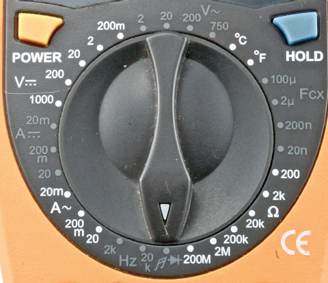
FIGURE 11-1 Multimeter range selection
This is typical of a medium-range multimeter costing around USD 20. We have probably only used four or five of the settings during the course of this book, so it is worth pointing out some of the other features of a multimeter like this.
Continuity and Diode Test
Starting at 6 o’clock, we have the Continuity mode, represented by a little music symbol and also a diode symbol. We have used the Continuity mode many times. It just beeps when there is very low resistance between the leads.
The reason a diode symbol appears here is because this mode also doubles for testing diodes. With some multimeters, this feature will also work on LEDs, allowing you to measure the forward voltage.
Connect the anode of the diode (the end without a stripe in a normal diode, and with a longer lead on an LED) to the red test lead of the multimeter, and then the other end of the diode to the black lead. The meter will then tell you the forward voltage of the diode. So, expect to see about 0.5V for a normal diode and 1.7V to 2.5V for an LED. You will probably also find that the LED glows a little.
Resistance
The multimeter in Figure 11-1 has six resistance ranges, from 200MΩ down to 200Ω. If you pick a range that has a maximum resistance lower than the resistor you are measuring, then the meter will indicate this. Mine does so by displaying a “1” on its own without any further digits. This tells me I need to switch to a higher resistance range. Even better, start at the maximum range and work your way down until you get a precise reading. For the most precise reading, you need the meter to be on the range above the one that tells you it’s out of range.
When measuring high-value resistors of 100kΩ and up, remember that you yourself are also a big resistor, so if you hold the test lead to the resistor at both ends (see Figure 11-2), you are measuring both the resistor in question and your own resistance.
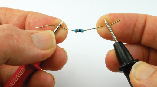
FIGURE 11-2 How not to measure high-value resistors
Use test leads with crocodile clips, or pin the resistor to your work surface with the flat of the test leads.
Capacitance
Some multimeters include a capacitance range. While not particularly useful for finding the value of unknown capacitors (capacitors have their value written on them), being able to test a capacitor and make sure it still has a capacitance something close to its stated value is useful.
The capacitance range on most meters is quite inaccurate, but then the values of actual capacitors—especially electrolytics—often have quite a wide tolerance.
In other words, if your meter tells you that your 100μF capacitor is actually 120μF, then that is to be expected.
Temperature
If your multimeter has a temperature range, it probably also comes with a special set of leads for measuring it, such as those shown in Figure 11-3.
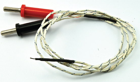
FIGURE 11-3 Thermocouple leads for temperature measurement
The leads are actually a thermocouple that can measure the temperature of the tiny metal bead on the end of the leads. This thermometer is a lot more useful than your average digital thermometer. Check the manual for your meter, but the range of temperature is likely to be something like –40°C to 1000°C (–40°F to 1832°F).
So, you can use it to check how hot your soldering iron is getting, or if you have a component in a project that seems to be getting a bit toasty, you can use this to check just how hot it is getting.
AC Voltage
We have not talked about AC very much in this book. AC stands for alternating current and refers to the type of electricity you get in a home wall socket’s 110V or 220V supply. Figure 11-4 shows how 110V AC household electricity voltage varies over time.
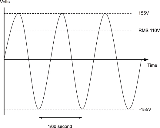
FIGURE 11-4 Alternating current
From Figure 11-4, it is apparent that the voltage actually reaches a peak of 155V and swings all the way negative to –155V. So you might be wondering why it is referred to as 110V at all.
The answer is that since a lot of the time, the voltage is quite low, at those times, it delivers very little power. So the 110V is a kind of average. It’s not the normal average voltage, because that would be (110 – 110) / 2 = 0V, and because half the time it is negative.
110V is the RMS voltage (root mean squared). This is the peak positive voltage divided by the square root of 2 (1.4). You can think of this as the DC equivalent voltage. So a light bulb running on 110V AC would appear to be the same brightness as if it were running on 110V DC.
You are unlikely to need to measure AC unless you are doing something exotic and dangerous, and you should not do that unless you are very sure about what you are doing and therefore probably already knew what I just told you.
DC Voltage
We have already measured DC voltage quite a lot—mostly at the 0 to 20V range.
There is nothing much more to say about this, except to always start with the highest voltage range you believe you are about to measure and then work your way down.
DC Current
When measuring current, you will probably find that for all current ranges you will need to use different sockets on the multimeter for the positive probe lead. There is usually one connection for low currents and a separate one for the high-current ranges (20A on the author’s multimeter; see Figure 11-5).
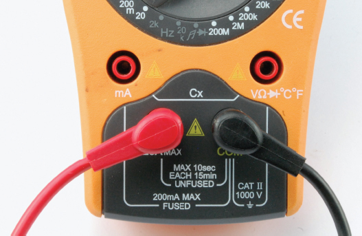
FIGURE 11-5 High-current measurement
There are two important points to consider here. First, if you exceed the current range, your meter will not just give you a warning, it may well blow a fuse within the meter.
The second point is that when the probe leads are in the sockets for current measurement, there is a very low resistance between them. After all, they need to allow as much of the original current as possible to flow through them. So, if you forget that the leads are in these sockets and go to measure a voltage elsewhere in the circuit, you will effectively short-out your circuit and probably blow the fuse on your multimeter at the same time.
So, just to reiterate, if you have been using your multimeter to measure current, ALWAYS put the probe leads back to their voltage sockets, as these are more likely to be used next. If you try and measure current with the leads in the voltage sockets, then all that will happen is that you get a reading of zero.
AC Current
The same argument that we gave for measuring AC voltage probably applies here. Exercise extreme caution.
Frequency
If your multimeter has a frequency setting, this can be useful. For example, in the section “How to Generate Tones with a 555 Timer” in Chapter 9 where we create an audio tone using a 555 timer, you could use this feature to measure the frequency of the tone being produced. This can be handy if you do not have access to an oscilloscope.
How to Use a Multimeter to Test a Transistor
Some multimeters actually have a transistor test socket where you can plug in a transistor. The multimeter will not only tell you if the transistor is alive or dead, but also what its gain (Hfe) is.
If your multimeter does not have such a feature, you can use the diode test feature to at least tell you if the transistor is undamaged.
Figure 11-6 shows the steps involved in testing an NPN bipolar transistor like the 2N3906.
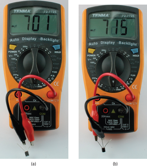
FIGURE 11-6 Testing a transistor
Put the multimeter into diode test mode and attach the negative lead of the meter to the center base connection of the transistor, and the positive lead to one of the other leads of the transistor. It does not matter if it is the emitter or collector (check the transistor’s pinout to find the base). You should get a reading, somewhere between 500 and 900. This is the forward voltage in mA between the base and whichever other connection you chose (Figure 11-6a). Then, move the positive lead to the other lead of the transistor (Figure 11-6b) and you should see a similar figure. If either reading is zero, either your transistor is dead, or it is a PNP type of transistor, in which case you need to carry out the same procedure but with the positive and negative leads to the multimeter reversed.
How to Use a Lab Power Supply
We came across a lab power supply back in Chapter 5. If you have your soldering equipment and a multimeter, then a lab power supply (Figure 11-7) is probably the next item to invest in. It will get a lot of use.
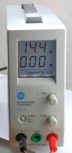
FIGURE 11-7 A lab power supply
The power supply shown in Figure 11-7 is a simple-to-use basic design. In the figure, it is being used to charge a lead–acid battery. You will find that you use it to power your projects while developing them. You should be able to get something similar for under USD 100.
It plugs into your home electrical socket and can deliver up to 20V at 4A, which is more than enough for most purposes. The screen displays the voltage at the top, and the current being consumed at the bottom.
The reasons why it is more convenient than using batteries or a fixed power supply are:
• It displays how much current is being consumed.
• You can limit the current consumption.
• You can use it in constant current mode when testing LEDs.
• You can adjust the voltage easily.
The control panel has an Output switch that turns the output voltage on and off, and two knobs that control the voltage and current.
If I am powering up some project for the first time, I will often follow this procedure:
1. Set the current to its minimum setting.
2. Set the desired voltage.
3. Turn on the output (the voltage will probably drop).
4. Increase the current and watch the voltage rise, making sure that the current isn’t rising to an unexpected level.
Introducing: The Oscilloscope
Oscilloscopes (Figure 11-8) are an indispensable tool for any kind of electronics design or test where you are looking at a signal that changes over time. They are a relatively expensive bit of equipment (from USD 200 on up) and there are various kinds. One of the most cost-effective types does not have any display at all, but connects to your computer over USB. If you don’t want to risk blobs of solder on your laptop, or wait for it to boot up, then a dedicated oscilloscope is probably best.
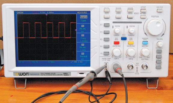
FIGURE 11-8 A low-cost digital oscilloscope
Entire books have been written about using an oscilloscope effectively, and every oscilloscope is different, so we will just cover the basics here.
As you can see from Figure 11-8, the waveform is displayed over the top of a grid. The vertical grid is in units of some fraction of volts, which on this screen is 2V per division. So the voltage of the square wave in total is 2.5 × 2 or 5V.
The horizontal axis is the time axis, and this is calibrated in seconds. In this case, 500 microseconds (μS) per division. So the length of one complete cycle of the wave is 1000 μS—or 1 millisecond—indicating a frequency of 1 KHz.
The other advantage of an oscilloscope is that the test leads are very high impedance, which means that they have very little effect on the thing you are trying to measure.
Software Tools
As well as hardware tools for hacking electronics, there are lots of useful software tools that can help us out.
Simulation
If you like the idea of trying out electronic designs in a virtual world, you should try one of the online simulators like CircuitLab (www.circuitlab.com). This online tool (Figure 11-9) allows you to draw your circuits online and simulate how they will behave.
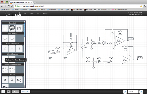
FIGURE 11-9 The CircuitLab simulator
You will have to pick up a bit more theory than this book covers, but a tool like this can save you a lot of effort.
Fritzing
Fritzing (www.fritzing.org) is a really interesting open-source software project that lets you design projects. It is intended primarily for breadboard design and includes libraries of components and modules, such as an Arduino, that can all be wired up (Figure 11-10).
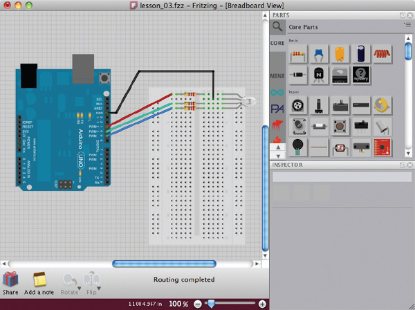
FIGURE 11-10 Fritzing
EAGLE PCB
If you want to start creating your own PCBs for your electronics designs, then look for the most popular tool for this, which is called EAGLE PCB (Figure 11-11). It allows you to draw a schematic diagram and then switch to a PCB view where you can route the connections between components before creating the CAM (computer-aided manufacturing) files, which you can then send off to a PCB fabrication shop.
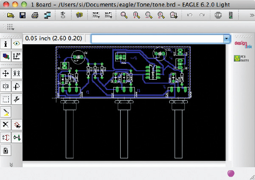
FIGURE 11-11 EAGLE PCB
Creating PCBs is a subject in its own right. For more information on this, take a look at the book Make Your Own PCBs with EAGLE: From Schematic Designs to Finished Boards by Simon Monk (TAB, 2013).
Online Calculators
Online calculators can make your electronics math a whole lot easier. Some of the more useful ones are:
• http://led.linear1.org/1led.wiz A series resistor calculator for LEDs
• http://led.linear1.org/led.wiz Designed for driving large numbers of LEDs
• www.bowdenshobbycircuits.info/555.htm A 555 timer IC component calculator
Summary
This is the last chapter in this book and I hope it will help you get started “hacking electronics.” There is much satisfaction in making something physical, or modifying a device so it does just what you want.
The line between producer and consumer is blurring more and more today as people start designing and building their own electronic devices.
The Internet offers many useful resources. The following web sites are worth a special mention:
• www.arduino.cc (for Arduino)
• www.sparkfun.com (modules and interesting components)
• www.adafruit.com (more cool stuff)
• www.dealextreme.com (bargains; search for LEDs, etc.)
• www.ebay.com (search for the same items as that in the other URLs in this list)
See also the components suppliers mentioned in the Appendix.
..................Content has been hidden....................
You can't read the all page of ebook, please click here login for view all page.