
Chapter 8: Designing Application Integration and Business Automation
In the previous chapter, we explored the concept of middleware in an application server. That's probably the most traditional meaning of middleware: you are using a layer providing some features to your code in order to standardize and avoid reinventing the wheel.
That's, of course, a concept inherent to the middleware term: something in between your code and the rest of the world (whether it's a database, the operating system resources, and so on). But middleware has a broader meaning in the enterprise world. One such meaning is related to the concept of application integration. In this sense, the middleware sits in between your application and the rest of the world, meaning other applications, legacy systems, and more.
In this chapter, we will look at some typical topics related to application integration. We will then have a look at another important related middleware aspect, which is business automation, more related to workflows and business rules. We will discuss the following topics in detail:
- Integration – point-to-point versus centralized
- Digging into enterprise integration patterns
- Exploring communication protocols and formats
- Introducing data integration
- Messaging
- Completing the picture with business automation
- Integration versus automation – where to draw the line
- Case studies and examples
After reading this chapter, you will be able to design and implement the most common integration, messaging, and business automation patterns, to be used in wider solution architecture design for your applications.
So, let's start with some reasoning about different integration approaches.
Integration – point-to-point versus centralized
Before digging into patterns and implementation techniques for application architecture, it's important to define that integration capabilities, as in making one application talk to another one, including different protocols and data formats, can be roughly split into two approaches:
- Point-to-point, where the integration capabilities are provided within each application component and components directly talk to each other
- Centralized, where a central integration layer plays a mediation role, hiding (partially or completely) the technological details of every component, hence facilitating the communication of components with each other
It's worth noticing that there is an important comparison to be made. We've already discussed, in Chapter 7, Exploring Middleware and Frameworks, that Java Enterprise Edition evolved into componentization with the goal of breaking monolithic approaches. This kind of architectural evolution is independent of software layers. This also means that other than the applications per se, the other architectural components (such as the integration layers) are impacted by such considerations, and so you may have a monolithic approach (as in centralized integration) and a modular approach (as in point-to-point).
The goal of this section is to give an overview of different integration approaches, starting from centralized, then modularized (point-to-point or cloud-native), touching on emerging topics (such as citizen integration), and in general providing a number of different architectural points of view on how to implement application integration.
To start, let's talk about a traditional, centralized integration approach: Service-Oriented Architecture (SOA).
Understanding service-oriented architecture
SOA is a broad term. It is more of an industry trend than a standard per se. It basically defines an architectural standard, somewhat similar to microservices (and different as well—more on this in Chapter 9, Designing Cloud-Native Architectures).
This whole concept is about creating reusable services. To do that, SOA relies on a number of different technologies, such as SOAP web services, an Enterprise Service Bus (ESB), and sometimes other components, such as a service registry (Universal Description Discovery and Integration (UDDI), which used to be a standard for this area), security, governance, and repositories.
The ESB is the relevant component for this chapter. Very often, SOA has been loosely adopted and ultimately abandoned in enterprise contexts (for reasons such as scalability and complexity), while the ESB has survived such architectures.
Enterprise service bus – what and why?
The ESB technology is commonly considered to have been born together with SOA, even though some of its concepts predate SOA technology.
Some commonly used ESB products include the following:
- Red Hat Fuse (https://www.redhat.com/it/technologies/jboss-middleware/fuse), distributed by Red Hat, and made using Apache Camel, which is the framework that we are going to see in this chapter.
- Tibco BusinessWorks (https://www.tibco.com/), distributed by Tibco. This is a widespread solution among many enterprise customers.
- MuleSoft (https://www.mulesoft.com), distributed by Salesforce, particularly suited to integrating SaaS applications.
While SOA focuses on supporting the construction of composable services and modular architecture (by stressing standard protocol usage, common security and governance policies, and a machine-readable registry of exposed services), ESB does some heavy lifting behind the scenes. An ESB provides all the glue needed for making the communication between different technologies transparent. The idea is we want to standardize services (such as SOAP) to make ESB interoperable and ultimately reusable to create new applications. We can integrate existing applications and services by using an ESB. An ESB revolves around the concept of a message, being the basic unit of information managed in each integration.
There are a number of ways to represent a message, but they normally include the following:
- A header, including a variable amount of metadata (usually in the form of key-value pairs), which may include information such as a unique ID, the message creation timestamp, and the original sender identifier (which is the system that generated the message).
- A body, which includes the message data (or payload). The data may be structured, meaning that it can be validated against a schema (such as .xsd for .xml files).
Given that the message represents the information flowing into our integration system, an ESB is then further composed of the following kinds of logical building blocks, dealing with such information:
- Connectors, providing interoperability (sending and receiving messages) with different technologies, such as databases, filesystems, and SaaS components.
- Formats, providing compliance with different message types, such as .json, .xml, and .csv. These are used to validate messages (to ensure the format is correct) or to convert a message between formats (to make the integration between different systems possible). We will see some widespread message formats in detail in the upcoming sections.
- Patterns, providing well-known integration behaviors, solving common integration problems such as content-based routing, splitting, and aggregating.
In this book, we will refer to integrations defined as routes. A route, in the context of integration, is composed of the following:
- One or more sources (or endpoints), which are basically systems generating messages. This is usually a connector implementing a specific technology (such as receiving REST calls, reading files, or getting data from a database).
- One or more destinations (or endpoints), which are the systems that receive the messages. Also, in this case, this is commonly a connector for a specific technology (such as inserting data into a SaaS system, writing files, or calling a web service).
- One or more integration steps, which are the business logic of the integration itself. Integration steps can imply changing the data format by calling a third-party system (using a connector) in order to retrieve (or send) data or even to implement a specific pattern (as per the previous section, so content-based routing, splitting, and so on).
This is what an integration route schematically looks like: a source, a destination, and a number of steps in between. The messages flow in such a way, following the required steps:

Figure 8.1 – Integration route
Please note that, usually, the steps are executed sequentially (straight through integration routes). However, according to specific patterns, it may be possible to have optional steps (skipped in some cases) or steps executed in parallel (for performance purposes). Now, when hearing about messages, you may get fooled into thinking that the concept of integration is inherently asynchronous. But in this context, this is not necessarily true. Conversely, integration may be (and usually is) a synchronous interaction, meaning that the initiator of such an integration process waits for the execution to complete.
Asynchronous integrations are behaviorally different. The initiator of such a process sends the message to the integration route and doesn't wait for the completion. It's usually enough to get an acknowledgment from the integration infrastructure, meaning that the system has taken charge of the message.
To implement such logic, usually, it's enough to use a message broker. In this way, you can publish the messages into a dedicated parking space (which is the broker) and have one or more consumers take it and execute the integration logic against it. Then, the integration logic may or may not signal the result of integration in some way (by using another message or synchronously calling an endpoint, such as a REST service). With this approach, you will have producers and consumers decoupled. We will see more about message brokers in the upcoming sections.
However, while most (if not all) of the principles of integration still hold valid today, ESBs have evolved and play a different role (and with different names) in the modern, cloud-native world.
Integration in the cloud-native world
With microservices and cloud-native architectures becoming popular, many started to question the role of ESBs and integration. The most common reason behind this is the lack of scalability. The microservices architectural approach heavily relies on the concept of product teams, each developing and having responsibility for a well-defined piece of software (implementing a subset of use cases).
A central ESB is simply against such an idea: in order to have service A talk to service B, you will need an integration route in the ESB, which means that both service A and service B are coupled to the system, both from a technical and an organizational point of view. You will have to pay attention to changes in your service that may break the compatibility with the central ESB (and the services dependent on it). Also, as a further side effect, you will introduce a single point of failure in the platform. Moreover, in the worst case, you'll have to raise a ticket to a specific team, which you'll need to implement yourself. This kind of complex synchronization and tight coupling between different projects is not the best in a fast-moving, self-service-oriented, cloud-native world.
But what happens if you remove the concept of the ESB from your architecture altogether?
Well, the problems that an ESB tries to solve will still exist, so you will need to solve them anyway. In order to integrate service A with service B (especially if service A and B use different technologies and protocols to communicate with each other), you will need to implement some glue. So, commonly, integration ends up buried in your services. While this is a somewhat widespread practice (more on this in Chapter 9, Designing Cloud-Native Architectures), I still think this has some downsides to be considered:
- You end up polluting your business logic with technological glue that needs to be encapsulated and isolated from your domain model (as per the patterns seen in Chapter 6, Exploring Essential Java Architectural Patterns).
- You will likely have many different implementations for the same use case (think about SOAP to REST or XML to JSON). This is inherently inefficient and may increase the occurrence of bugs.
- You will hardly reach the complete decentralization of integration capabilities. Supporting infrastructures for things such as service discovery, observability, and security will likely be needed, and are more difficult to distribute (and decentralizing such capabilities may be just wrong).
As usual, when we look at these kinds of considerations, there is not a complete answer that's good for everybody. Of course, relying on a complex and extensive centralized ESB may be a bottleneck (both technical and organizational), while trying to decentralize such capabilities may lead to repetition and a lack of governance. A common approach to resolving this kind of dilemma is basically to still rely on centralization but make it lighter and smarter. Some approaches to reduce coupling and implement more flexible integration include the following:
- It may be that your ESB becomes a set of reusable integration components (organized around capabilities) that you basically re-instantiate (and maybe modify) in your project context (hence, depending on the team providing such components, in a way).
- Such components may also not even technically be artifacts. It may be that you simply share the best practices and code samples (or even the complete code) with the project teams working with related projects. In this way, you still have some (light) control over what's going on, but each team has more freedom in understanding the component, building it, evolving it (if needed), and maybe reverting changes into the main collection via a pull request. Hence, this creates an open community behind integration capabilities across different projects.
- Another approach is to still use an ESB but limit it to one small boundary. So, instead of having a single, huge integration bus for the whole company, we can have smaller ones by department or project. They could be logical tenants of the same ESB (hence, reusing skills and best practices) or even completely different ones, based on different technologies. Once again, this is kind of a trade-off: you may still end up having repetition and/or bottlenecks, so the downsides may outweigh the benefits if you don't manage it properly.
So, even though ESBs are often viewed badly in modern architectures, the need for integration is still there, and it's important to properly study your environment in order to make good choices and evolve it correctly.
Citizen integration
One last trend that is worth highlighting is citizen integration. This is a trend highly studied by consulting firms and considered to be a game-changer in some scenarios. Basically, citizen integration is about having non-technical users (such as business analysts, managers, and other similar roles) being able to create integrations on their own, without having to rely on developers and other technical teams. To do so, our citizen integrators rely on highly expressive and user-friendly interfaces, usually simply accessible from the browser, and provide integration capabilities with wizards and drag and drop. Such interfaces are part of what's commonly called an Integration Platform as a Service (IPaaS).
As you can imagine, this is too good to be true: IPaaS and citizen integration is, of course, not a silver bullet. It's hard to solve every possible use case with such tools that commonly work very well on a specified subset of the infinite integration problems. There are technical implications too. IPaaS is a platform that needs to be configured and connected to backend systems, which can be a challenge (also from the security point of view), especially if you consider that such platforms are commonly hosted on the cloud.
So, I think that the whole concept of citizen integration is still relevant and deserves to be thoroughly considered in your integration strategy but usually does not solve all the integration needs a complex enterprise may have and should be targeted at a well-defined subset of them.
In this section, we explored the basic components and characteristics of integration, including the concept of an integration route, steps, and messages. We also discussed what an ESB is and how such a concept is evolving, starting from centralized SOA and going toward more modern, decentralized, self-service approaches.
Beyond the semantic difference and historical evolution of the integration technologies, there is a common sharing of knowledge about the integration patterns used. We will look at them in the next section.
Digging into enterprise integration patterns
The most complete and widely used collection of integration patterns is enterprise integration patterns. Enterprise integration patterns are a list of recipes for implementing well-known solutions to well-known problems in integration. Indeed, very often, the issues that occur when implementing an integration solution fall into some recognizable categories. According to common groupings, such categories include the following:
- Message routing, which includes all the issues and solutions about message dispatching, with topics such as filtering, routing, and aggregating messages
- Message transformation, which is more focused on the message content, including all kinds of message manipulation techniques, such as enriching, filtering, and uniforming the message content
- System management, which is a category including known techniques for managing and operating the integration system as a whole, including wiretaps, message archiving, and tracing
In this section, we will see a curated list of these patterns.
Message routing
The message routing family of integration patterns is a set of integration techniques aimed at programmatically defining the destination of an integration message. In this way, you can sort messages or define complex integration logic by chaining different integration steps designed for different types of messages. The most commonly used routing patterns are the following:
- Message filter: This is probably the easiest routing pattern. Here, a message filter simply discards the messages that don't comply with a specified policy. Such a policy can be a rule as complex as needed, which takes the message as input and outputs a Boolean value. The message is discarded according to that value. Common implementations of such a pattern include the comparison of some message attributes against a defined set of values. An example of a message filter is shown here:

Figure 8.2 – Message filter
As you can see in the diagram, the message filter applies a policy to input messages and discards the messages that are not compliant with such a policy.
- Content-based router: This is slightly more complex than the filter pattern. Content-based router dispatch uses logic similar to the message filter. As a result, the message can be delivered to two or more different destinations (including other integration steps, queues, or other kinds of endpoints). Of course, unlike the message filter use case, the criteria here don't output a Boolean value, but two or more different results mapping to the destination endpoint:

Figure 8.3 – Content-based router
We will further discuss the content-based router approach in Chapter 9, Designing Cloud-Native Architectures, as it will conceptually support some interesting cloud-native behaviors in the area of release management.
- Aggregator: The aggregator is an interesting pattern because, unlike the others described in this list, it is a stateful one. In the aggregator pattern, the incoming messages are collected (according to some defined policy) and composed as a more complex message. Being stateful is relevant here because you may want to understand what happens if such components crash when some messages are currently in flight, and how to react to such situations:
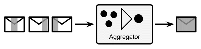
Figure 8.4 – Aggregator
- Splitter: This complements the aggregator pattern. A complex message is taken as an input and is divided into two or more different messages. Then, it may be followed by a content-based router to help dispatch each message to a different path to implement different business logic:

Figure 8.5 – Splitter
- Routing slip: This is a slightly different pattern, useful to model complex integration logic, unpredictable beforehand. With this pattern, you basically attach metadata to each of your messages and identify the next integration step (if any) that needs to be applied against such a message. This metadata can be calculated using any policy relevant to your use case. You will then need to have a component (similar to a registry) that associates the key present in this metadata with a defined destination (being another component or other endpoints):

Figure 8.6 – Routing slip
In the previous diagram, the objects with a shape (a cross, star, or triangle) represent the available integration steps. By implementing the routing slip integration pattern, each message obtains a list of integration steps, which is attached as metadata to the message itself and calculated starting from the message content. In this particular case, our message will then go through the steps represented by the triangle and the cross mark, while skipping the step represented by the star.
Now let's move on to another family of patterns, focused on message transformation.
Message transformation
As it's easy to imagine, message transformation patterns focus on changing the data format of the message body. This is useful when connecting systems based on different data models or formats (think about connecting a database to a REST service or a legacy application to a SaaS solution). The pattern used for message transformation is generically referred to as message translator and simply operates on the message body, manipulating it to change the format. Apart from this generic description, there are some specific, recognizable types of message translators. Some examples are the following:
- Content filter: A content filter is somewhat analogous to the message filter. But instead of dropping the message as a whole when the content doesn't comply with a set of rules, it operates within the message data, discards part of the content, and only keeps the part of the message that is relevant (by checking it against a set of conditions):

Figure 8.7 – Content filter
- Content enricher: This complements the content filter. A content enricher adds some new data to the message content. To do that, it relies on an external repository (such as a database). The enrichment algorithm may use a replacement (each value corresponds to another one, like when changing a ZIP code for a city name), a fixed value (adds the same value to each message), or more complex logic. Here is a diagram of it:
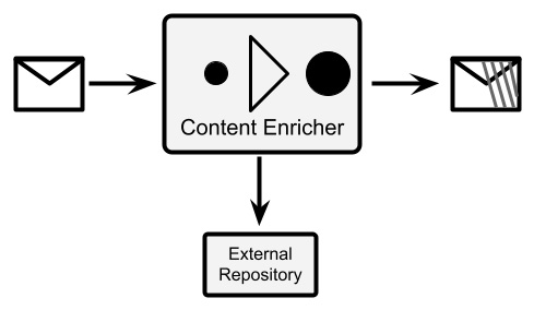
Figure 8.8 – Content enricher
- Canonical data model: This is a common approach in ESBs. Basically, in order to decouple the message format of all the participants of the system, a neutral format is defined to be used in the ESB. This is usually a superset of all the messages, or simply a different format. In order to implement this approach, each system is plugged into the ESB with a special Message Translator component, which translates the native format of each system to the canonical data model, and vice versa:
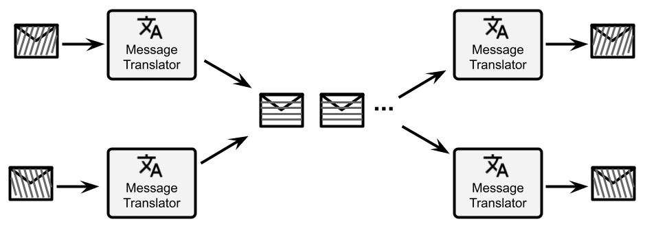
Figure 8.9 – Canonical data model
- Normalizer: This is a special case of the canonical data model approach. In order to maintain the common data format inside the ESB, but use a single endpoint for each external system, you can use the router component (as per the Message routing section). The only purpose of such a component will be to look into the messages, recognize the message format (by looking into the body or header), and route it to a specific message translator, which must be able to translate the message format to the common data format:

Figure 8.10 – Normalizer
These are just some well-known examples, but the message translators are usually something very specific to the business logic, including custom approaches, such as the merging of different fields, string formatting, and calculations. In the next section, we will talk about system management patterns.
System management
System management patterns are essentially positioned as a way to monitor and manage integration routes in production. So, in this sense, they are useful for the operation of the platform and ensuring the service level for the customer. However, there are several patterns that could also be useful for implementing logic that solves specific use cases (besides being useful for monitoring and management). Such patterns include the following:
- Detour: A detour is a practical technique for ensuring a particular treatment for some messages. In practice, you will have a content-based router triggering a specific path when some condition happens. The content-based router may be triggered by certain content in the incoming messages (as usual) or may be based on specific external conditions (such as special messages coming in, and maybe even on specific channels different from the one on which the rest of the traffic comes). When activated, the detour will route the messages to a different path that may be used for debugging, testing, or validating such messages.
The detour opens a lot of interesting (and modern) use cases, such as the concept of the circuit breaker and other cloud-native patterns (we'll see more about this in Chapter 9, Designing Cloud-Native Architectures). In the following diagram, there's an example of a detour: each message is inspected and, depending on the content (using the content-based routing pattern), it is routed to the normal path or a special path (if some conditions are met). In this way, you can activate special handling for some specific messages:
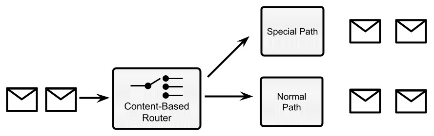
Figure 8.11 – Detour
- Wiretap: Wiretap is a pretty simple pattern. You basically add a step to the integration route that duplicates all the incoming messages and sends a copy to an alternative channel (while a copy continues to travel on the usual integration route). In this way, you can monitor the incoming messages (such as counting them or inspecting them) and analyze the system behavior with real data:
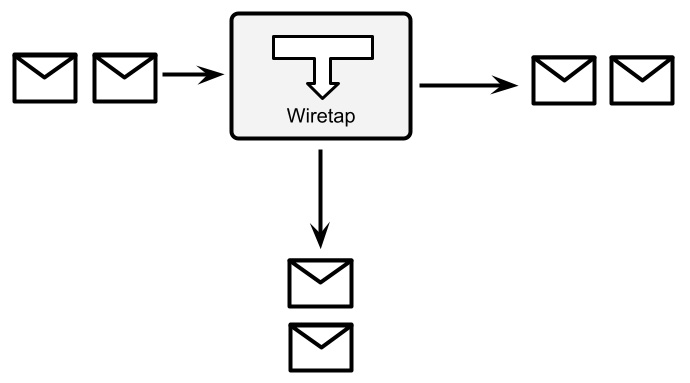
Figure 8.12 – Wiretap
- Message history: Message history is a simple and structured way to understand the path that each message flows through. Think about an integration route with multiple paths (such as conditional ones, which are diverted by content-based routers and similar patterns). It may be useful for debugging purposes or even mandated for regulation purposes (such as audit logging) to have a registry of every step spanned by the message. Message history suggests doing so by attaching some data at each step. This is commonly done by adding a unique key for each system in a specific message header. At the end of the integration route, you will have a list of keys identifying each integration step. Even in this case, this is not so different from tracking a cloud-native pattern needed for heavily distributed architectures (such as microservices). Here is a diagram for visualizing message history:

Figure 8.13 – Message history
In this diagram, we see the integration steps are represented by a symbol (a cross mark and a triangle). Each time a message passes into an integration step, the message is marked with an identifier corresponding to it. So, at the end of the integration route, you know exactly the path that each message has followed (if it skipped any step, went through optional paths, and so on).
- Message store: There are use cases in which you want to know exactly the content of each message, including intermediate transformation. This can be required for a subset of messages (such as for troubleshooting purposes) or all messages (as we saw in the message history pattern, that may be for audit logging requirements). The message store pattern suggests implementing this case by attaching a wiretap to each integration and diverting every message (or some messages, conditionally) to a shared message store (such as a database).
It may be necessary to add some complementary metadata, such as a timestamp, an identifier for each step, and maybe a signature (for checking the data integrity). In some cases, the message store may need to implement specific technologies for non-repudiation, such as Write Once, Read Many (WORM), in terms of special anti-tampering hardware. The following diagram visualizes the workings of the message store:
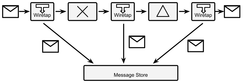
Figure 8.14 – Message store
- Test message: This is a simple health check for integration routes. Basically, in order to understand the message flow (such as whether there is any intermediate component losing messages or taking too long to process them), you inject some special test messages into the integration route. You will then need a content-based router at the end of the integration route in order to identify such special messages (such as looking for a particular pattern in the data or a special key in a header). Then, you'll need to route it to a monitoring system, which can then check whether every message is returned (so that there is no message dropping) or calculate the elapsed time, and so on.
Bear in mind that every intermediate step may need to be aware of or at least resistant to this kind of test message. This means that if you are calling external systems or writing data to a database, you may want to instruct a specific step to skip in the case of test messages. In the next diagram, we can see a graphical representation of this pattern, that is, a content-based router that identifies a special test message and routes it to a monitoring system, instead of the standard integration flow:
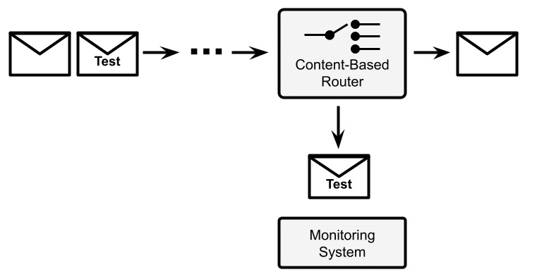
Figure 8.15 – Test message
The group of system management patterns is different from what we have seen so far. They are less focused on application logic and data and more on the monitoring, maintenance, and operation of the integration infrastructure. This does not mean that you cannot use them to implement some use cases (think about the Wiretap pattern, which can be a way to implement multiple different behaviors on the same message), but that's for sure not the main usage.
As we said, all the patterns that we have seen so far are useful both for synchronous and asynchronous integration. However, when it comes to async use cases, a whole new set of considerations arises in terms of messaging brokers and integration with them. This is partially related to enterprise integration patterns and partially implicit in the technology itself (which may be referred to as message-oriented middleware, or more commonly, queue managers). In the next section, we will have a look at those cases.
The Camel integration framework
Apache Camel is likely the most famous open source integration framework. It was created in the years after 2000 and it has been evolving constantly since then, mostly because of the very active community behind it. At the time of writing, Camel has hundreds of contributors and thousands of stars on GitHub.
Camel isn't exactly an ESB but can be used as one. It is more like a core engine containing integration capabilities. Indeed, Camel implements the enterprise integration patterns by design (and other patterns, including some techniques for cloud-native applications). Moreover, Camel includes hundreds of connectors for specific technologies (such as queues, databases, and applications) and data formats (such as JSON and XML). Camel can be run standalone or on top of a selection of runtimes (including Quarkus, which we saw in the previous chapter). It can be deployed as an ESB (centralizing all the integration capabilities at one point) or embedded in your applications (distributing such capabilities where it's needed).
The Camel DSL
Camel exactly implements the concept of routes as we have seen it so far, as a sequence of specific steps to run against each message (intended as a piece of data). In order to specify each route with Camel, you can use a .xml file or the Java Domain-Specific Language (DSL), which is basically a dialect of Java made for the purpose of expressing concepts specific to the Camel world. For the purpose of this section, we will use the Java DSL, which allows the definition of routes using a Java-fluent API.
This is what a simple integration route that converts JSON to XML looks like:
from(platformHttp("/camel/hello"))
.unmarshal()
.json(JsonLibrary.Jackson, MyClass.class)
.marshal()
.jacksonxml()
.to(file("/myfilePath?fileName=camelTest.xml"));
As you will see, there is from, which is the endpoint starting the integration route (in our case, by exposing an HTTP REST endpoint, by using a component called platformHttp), and to, which writes the final result to a file (by using the file component). In between, you can see an example of data transformation, including the mapping (unmarshal) of a JSON object to a Java object, and then mapping back (marshal) of such a Plain Old Java Object (POJO) to XML.
We will see a more complete example in the Case studies and examples section. Now, let's have an overview of the messaging concepts.
Messaging
Messaging is a core concept in the integration world. In the previous section, we discussed messages as the basic unit of data flowing inside each integration step. Let's now focus a bit more on the concepts specific to messaging, such as message brokers, asynchronous interactions, producers, and consumers. First, we will start with the broker concept.
Defining the broker concept
A broker is a common, elementary concept in IT. It can be intended as an architectural solution as well as a technology.
From an architectural standpoint, a broker allows producers to push messages into an intermediate system (a broker itself), which dispatches it to one or more consumers. The message broker concept is described in the homonymous enterprise integration pattern.
Beyond this simple description, a huge number of variants and other concepts can be elaborated on, influenced by the underlying technology and the use case we are trying to model. Examples of broker technology include Apache ActiveMQ, Kafka, and RabbitMQ.
Now, let's dig into some basic messaging concepts.
Queues versus topics
The first categorization that is common in a Java programmer's mind is queues versus topics. This differentiation has been made famous by the Java Message Service (JMS), which is the API defining messaging practices under the Java Enterprise standard.
In the JMS world, a queue is defined in the message broker, which takes care of messages sent by producers and dispatches them to a consumer. If there are no consumers available, the queue stores them until one connects, trying to avoid the loss of messages. This is referred to as the store and forward approach. The queue can also be used for point-to-point connections (one producer and one consumer) as the point-to-point channel enterprise integration pattern.
A common usage of queues is to have one or more producers and a number of consumers that may also vary with time, depending on the number of messages to work effectively (an example of horizontal scaling). In this case, each consumer takes a message in an exclusive way, usually with some sort of transactional semantic. This pattern is named Competing Consumer in the enterprise integration patterns world.
A topic has a slightly different semantic. In a topic, the messages sent by producers are propagated to all the consumers connected in that particular moment. This is similar to the concept of a broadcast, commonly used in networking. Consumers usually lose all the messages sent before they were connected with that particular topic.
Queues and topics are two high-level concepts that encompass, in recognizable names, a number of different characteristics of the messages, producers, and consumers involved (and may include different variants). In the enterprise integration pattern world, a queue is defined as a point-to-point channel including the Competing Consumer pattern. The topic is instead defined by the concept of the publish-subscribe channel, in which you have one or more producers, and not every consumer is competing, but instead receives a copy of each message, in a broadcast fashion, where everybody receives every message.
Message quality of service
An important concept, often related to the underlying messaging technology, is the quality of service (also known as QoS). QoS, in the context of messages, refers to the commitment that the broker takes on when it comes to delivering our message to consumers. This refers to what happens after the producer puts a message into the system and gets an acknowledgment from the broker. Then, based on the configuration of the system, three delivery scenarios are possible:
- At most once, which means that the message may not be delivered at all, but if it's indeed delivered, it will not be delivered more than once. Here, the use case is about best-effort messages (so, we can lose some), where duplication is to be avoided (because it pollutes our downstream systems). A real-world example of this is currency exchange rates. These are values that change very often, and in some scenarios (such as high-frequency trading), you would rather lose one value (which is valid for a very short period of time and overridden by a new one) than just having a ghost value caused by a message duplicate. Here is a diagram to illustrate this:
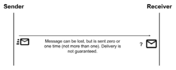
Figure 8.16 – At most once message delivery
- At least once, which implies that messages will never get lost, but may be sent more than once to consumers. Here, the use case is, of course, the opposite to the previous one. In particular, it's more important to not lose any messages. In the real world, this could be an Internet of Things (IoT) scenario: imagine collecting field data from an industrial machine. You may prefer to have all messages (which, for example, may highlight an imminent failure), even if this means that you may have duplicates (which could be discarded in downstream systems or simply be considered as harmless). The following diagram exemplifies this:

Figure 8.17 – At least once message delivery
- Exactly once, which is the ideal scenario that you can imagine when approaching a messaging system. Needless to say, here the broker guarantees that your message will be delivered and no duplicates will exist. This, of course, may be a mandatory requirement in some kinds of use cases. Typically, in the real world, this is related to financial services: once you have entered a payment transaction, you cannot afford to lose it, nor execute it twice. The following diagram demonstrates this:
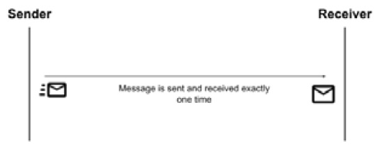
Figure 8.18 – Exactly once message delivery
Now, you might be wondering, why don't we simply stick with the exactly once delivery scenario every time, and simplify our lives? The answer is simple and expected: exactly once is the most expensive of the three. Since the system will need to lock at some point (to check for duplicates), providing there are the same number of messages and the same hardware, exactly once would probably be the worst choice in terms of performance. This may not be noticeable with low traffic, but it may be crucial if you are designing with high-traffic peaks in mind.
Zero message loss
In messaging, it's a common requirement to guarantee the zero loss of messages (and as we have seen, this is a combination of at least once and exactly once QoS). In order to provide such requirements, messaging systems usually use two kinds of solutions:
- Message persistence, which is usually on a filesystem or database. This means that a producer will get an acknowledgment for putting a message in a queue only after the message is serialized on the persistent storage. In this way, in the event of a system crash, it is guaranteed that the situation can be recovered by reading from the journal. Here is a diagram for demonstration:
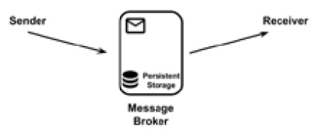
Figure 8.19 – Message persistence
- Message copies, which are sent to different instances of the message broker. The producer gets the acknowledgment for putting a message in the queue after a copy of the message is propagated (over the network) to one or more (usually configurable) backup instances of the messaging system. This guarantees that, in the case of our messaging system crashing, the backup instances can take over and deliver the message. Of course, in this scenario, you are reducing but not eliminating risks. You may still end up with all the instances down in the case of catastrophic failures, and you should plan accordingly (such as using different physical locations, where possible), as shown in the following diagram:

Figure 8.20 – Message copies
Zero message loss scenarios almost always have performance impacts.
Other messaging concepts
As has been said, depending on the underlying implementation technology, there are a number of use cases that can be implemented in the messaging world. Here is a list of the most useful ones:
- Dead Letter Queue (DLQ): This is pretty common in any messaging system. A DLQ is basically a special location, as shown in the following diagram, to redirect messages when certain conditions happen (such as no consumers are available after a certain amount of time, as we will see in the next point about time to live) or simply when the broker doesn't know what to do with a message (for example, for runtimes or configuration errors). It's a common behavior to persist and monitor the DLQ as an indicator if something goes wrong and if the messages contain any recoverable data.
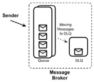
Figure 8.21 – Dead letter queue
- Time to live: When used, time to live is an attribute associated with each message when it is inserted into the queue. It will define the expiry of the message: if a message is still in the queue after the expiration has occurred (because there are no consumers or they aren't fast enough), it could be discarded or moved to a special queue (such as the DLQ).
It's an elegant way to model some use cases: there are some kinds of data that are just useless after a certain amount of time has passed (maybe because some more recent information has become available by that time). In this way, you avoid putting overhead on the consumers. However, if you have too many messages expiring, there is probably a need for something else to be tuned (such as the availability and performance of the consumers).
- Duplicate checks: Some broker implementations can check messages against duplicates. This is usually a delicate matter to handle. There are different possible implementations, but the most common one involves the presence of a unique identifier for the message (which can be provided externally, such as a database key, or calculated by the broker, such as a hash) and storing such messages in a proper data structure (such as a database or a key-value store). Each message is then checked against such a structure, and if a duplicate is found, the message is discarded. The message store commonly has a fixed maximum size or an expiration to avoid indefinite growth.
- Priority: This is a common requirement for some use cases. Basically, it is the possibility to identify some messages as having a higher priority than others (usually setting a specific header), to inform the broker to have it delivered before the other messages in the queue (if present).
- Bridge: This is an infrastructure for multiple queue management that basically passes messages from one broker to another, as shown in the following diagram. It can copy the messages or just move them to another queue and broker. It's useful to interface with different technologies and existing systems, or even to provide reliability (such as a multi-site messaging system):

Figure 8.22 – Bridge infrastructure
- Filters: This is a common functionality of brokers, which mimics the content-based router pattern that we have already seen. It's basically a configuration instructing the broker to move messages between different queues when some conditions happen (such as if a special header is present or a condition is met in the message payload).
- Chunking: It may happen that a queue is used to transfer data of a consistent size. In order to avoid hogging the broker and handle very big messages, a broker can implement chunking. As it's easy to imagine, a big message is then chunked into smaller parts before being delivered, as shown in the following diagram. However, some mechanism is needed to reconstruct the message on the consumer's side. A common one is to tag each chunk with an identifier and a sequence number:
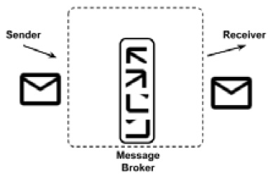
Figure 8.23 – Message chunking
- Schema: It's sometimes useful to perform some validation on the messages inserted into the broker. A smart way to do that is to define a data schema (such as an XSD). The messages that are not compliant with such a schema are then discarded or moved to special queues (such as the DLQ), as follows:

Figure 8.24 – Data schema in messaging
This list completes our considerations about messaging. In this section, we have seen many constructs (such as brokers, queues, and topics) and configurations (such as QoS and zero message loss) that can be used to model a lot of different use cases. In the next section, we will focus on the protocols and formats of data.
Exploring formats
As we have seen in the previous sections, integration works with flows (synchronous or asynchronous) of small information bites (in the form of messages) to be acted upon. Such messages are usually formatted into well-known shapes. Let's have a quick overview of the most common ones.
XML
Ostracized for being verbose and cumbersome, and often considered old and past it, eXtensible Markup Language (XML) is simply here to stay. And for good reason, since, as we will see, it has a number of powerful and useful features. To start, XML files are expressive and structured, and there is a lot of tooling supporting them.
This is what a simple XML file looks like:
<?xml version="1.0" encoding="UTF-8"?>
<myTag>
<mySubTag myAttribute="myValue" >my content</mySubTag>
</myTag>
I'm sure everybody is familiar with XML; however, just to set common ground, the characteristics of a proper .xml file are as follows:
- It is text-based.
- There is a special tag at the beginning, called a prolog, specifying the version and encoding of the document (such as <?xml version="1.0" encoding="UTF-8"?>).
- There is a root tag including all the other tags in the document (excluding the prolog, which is considered to be a special element of the document).
- Each tag of the document can include text content (<myTag>my content</myTag>) or other tags (<myTag> <mySubTag>...</mySubTag> </myTag>). This is called an element.
- Each tag may include one or more key-value pairs, called attributes (such as <myTag myKey="myValue" ...>...</myTag>).
- Each tag must be opened and closed properly (such as <myTag>...</myTag>). The shorthand form is allowed if the tag is empty (<myTag/>). Tags must be properly nested: if you open a tag, you can open other tags inside it, but you need to close the parent tag before closing the child tags (<myTag><myOtherTag></myOtherTag></myTag> is allowed, while <myTag><myOtherTag></myTag></myOtherTag> is not).
- Special characters, such as <, >, and ", must be replaced with special entity references, such as <, >, and ", which are commonly called escape sequences and are basically one-to-one mappings between each special character and the related entity reference.
Most likely, such rules are just taken for granted: after all, you have probably already edited a .html file (which is a sibling of the .xml file) or a configuration file in the XML format.
As mentioned, detractors of XML say that it is long and hardly human-readable, not to mention the frustration of parsing errors when you try to manually edit it: one single character off will often corrupt the whole file.
However, due to this simple but powerful syntax, XML provides some interesting features:
- It allows for automatic validation by using an XML schema (XSD): An XSD is considered a class when the .xml file is considered to be the instance. An XSD can be applied to a given .xml file to ensure it is compliant with such a specification. That's crucial in machine-to-machine interactions and may reduce the number of runtime errors. By defining an XSD, you are basically creating an XML dialect suitable for your own problem.
- It can be searched (using queries): By using technologies such as XPath and XQuery, you can define patterns that will allow you to find a specific portion of a .xml document. That's particularly interesting in the context of integration (think about the content filter or content-based router patterns that we have seen), so most of the available ESB technology provides support for this kind of feature.
- It can be automatically transformed: By using the XSLT dialect, you can define transformations for .xml files. In this way, you can set rules allowing a processor to change a .xml file from one definition to another, mapping and transforming tags in the source files to something different in the target files. Also, in this case, it's an interesting feature in the integration world that can basically cover most of the message transformation patterns.
Talking about XML is like talking about Java: there is plenty of criticism around calling it an old and outmoded standard. However, while more modern approaches have, of course, come along and deserve attention, XML, like Java, provides proper support for a wide range of use cases to date, due to a structured set of rules and the extensive availability of supporting tools and technology.
Working with XML in Java
The translation of .xml files from and to Java objects is a pretty common task. There are basically two ways to do so:
- The first (and now less common) way to parse XML is to use streaming. This is useful if you don't know the structure of the .xml document upfront that you are going to parse. So, you rely on a streaming approach, in which XML is traversed from the beginning to the end, and each element triggers events, such as the start element and the end element.
Each event contains the data for the particular elements (contents and attributes). While it is not particularly widespread today and has some practical disadvantages (the creation of Java objects is cumbersome and random access to elements is not allowed), this kind of parsing has the advantage of usually being very efficient, especially in terms of memory usage. The most famous implementation of XML streaming in Java is SAX (www.saxproject.org).
- The most common way to implement XML serialization and deserialization is to use direct mapping. With this approach, there is a direct link between elements (and attributes) of the XML content and fields of the POJO. Such linking is defined by a proper mapping, which could be defined in configuration files or, more conveniently, by using annotations. Part of the mapping can also be implicit (such as fields mapped to homonymous XML elements and vice versa).
Nested elements are commonly mapped using collections or other complex subobjects. This approach is heavily used in integration (but not only that), as XML content is mapped to Java objects that are then used for business logic, checks, and other interactions. The most common implementation of XML mapping in Java is provided by Jakarta XML Binding (JAXB), which is part of the JEE specification. It is also worth knowing that Jackson, a JSON library that we saw in Chapter 7, Exploring Middleware and Frameworks, in the JPA and REST (and more) with Quarkus section, can also be used as a framework for REST serialization for XML mapping (and supporting other data formats too).
Whatever the approach is for parsing, mapping XML to Java is a pretty common use case in the enterprise world, as XML is a widely used format for data interchange (used in many different industries, including banking and healthcare).
In the next section, we are going to see a challenger of XML in the field of web services: JSON notation.
JSON
We have already seen and used JSON, in Chapter 7, Exploring Middleware and Frameworks, in the Jakarta RESTful web services section. Now, it's time for a bit of theory about it.
JSON is the acronym for JavaScript Object Notation. It is a text representation for representing data. The technology was born in the context of web development when the AJAX application became widespread. We will see more about AJAX and web development in Chapter 10, Implementing User Interaction, but for now, it's enough to know that it's now a common technology that started to be used around 1999 and is about web pages dynamically requesting data from the backend after the page is downloaded by the browser. To do so, the JavaScript language is used on the client side for both requesting and parsing such data.
While it is possible to use XML to serialize such data, JSON emerged as an effective and simpler alternative. JSON is indeed native to JavaScript, and the serialization/deserialization of JavaScript objects to JSON is done without the need for external libraries. This is what a simple JSON file looks like:
{
"myKey":"myValue",
"myOtherKey": 42,
"mySubObject":
{
"mySubKey": "mySubValue",
"myArray":[ "value1", "value2", "value3" ]
}
}
JSON is basically made of primitive types (such as strings, Booleans, and numbers), objects, which have one or more key-value pairs enclosed in curly brackets, and arrays, which are collections of other objects, arrays, or primitive types, enclosed in square brackets. The thing that made JSON popular, other than being native to JavaScript, is that it is less verbose and more human-readable than XML.
The major criticism of JSON is that it's less structured than XML, which has produced a number of other concepts and technologies in terms of validation (XSD, as we saw in the previous section), web services (SOAP), querying (the aforementioned XPath and XQuery), and more (such as security and other features associated with the SOAP standard).
However, JSON nowadays covers some (if not all) of those features, both natively and via third-party implementation. It's worth mentioning that JSON Schema is a technology available for syntactic validation, and other implementations, such as JSONPath, are used for querying JSON documents. Moreover, JSON is commonly used as a base technology in NoSQL document databases (we'll see more on this in Chapter 11, Dealing with Data). In the next couple of sections, we are going to see the interactions between JSON and YAML (which is a widely used data format nowadays), and, of course, JSON and Java.
JSON and YAML
YAML Ain't Markup Language (YAML) is an alternative data serialization language created in 2001 that became widespread with the popularity of Kubernetes because it's used as a format to encode resources and configurations (we'll see more on Kubernetes in Chapter 9, Designing Cloud-Native Architectures). YAML is also widely used in frameworks such as Quarkus and Spring Boot for managing configurations of microservices. YAML is designed to be easily human-readable and is heavily based on key-value-like structures (and more complex objects), which are organized using a syntax similar to the Python language, which relies on spaces to define hierarchies.
This is what a simple YAML file looks like:
---
myKey: myValue
myOtherKey: 42
mySubObject:
mySubKey: mySubValue
myArray:
- value1
- value2
- value3
It's interesting to note that, since YAML can (but does not enforce doing so) use a syntax based on curly brackets, it is indeed a proper superset of JSON. This means that YAML provides some additional features that are not present in JSON (such as comments and richer data type management).
A YAML parser, in other words, can parse JSON documents. Moreover, if the additional features are not used, a YAML document can be directly translated to JSON (and vice versa) without losing any data. Indeed, the example for YAML that we have seen is the exact representation of the example for JSON that we saw in the section before.
Working with JSON in Java
As we already know, the parsing of JSON files is native in JavaScript, while in Java the already mentioned Jackson library is a common way to work with JSON. The mapping, as we saw in Chapter 7, Exploring Middleware and Frameworks, is made by associating (explicitly by using an annotation, or implicitly by relying on the name) each field of the POJO to each key of the .json file, similar to the approach of JAXB for XML mapping. This kind of mapping is particularly useful when dealing with REST web services.
Protobuf
Protocol Buffers (Protobuf) is a slightly different way to store data. It was created by Google as an internal tool (widely used within their infrastructure) and then was open sourced. The most notable difference from the other technologies seen so far is that Protobuf is a binary protocol. As per the other technologies seen so far, it is language-independent, so you can use it as a way to communicate from Java to other technologies.
Google (and the other organizations and contributors involved in the open source community) provides tools for serializing, deserializing, and in general working with Protobuf, including an SDK for Java. The SDK contains a compiler (protoc) that acts as a source code generator. Basically, when given a specific configuration (in a .proto file), it creates all the needed scaffolding for serializing and deserializing POJOs to and from byte arrays (and they then can be sent over the network, persisted to a file, or used as a message). Since the output is in a binary format, it is very efficient and optimized.
The configuration is basically a declaration of all the fields contained in the POJO you want to serialize, plus some metadata:
syntax = "proto3";
option java_outer_classname = "MyPojoProto";
option java_package = " it.test";
message MyPojo {
string myField = 1;
repeated string myList = 2;
int32 myNumber = 3;
}
Here are some details about the preceding block of code:
- syntax refers to the version of Protobuf used. Proto3 is the current version at the time of writing.
- The two option keywords are specific to Java. They will configure the name of the class and the package containing all the autogenerated facilities.
- message is the description of each field. Other than the name of the object (MyPojo), it defines the name of each field and the primitive type (string, int32, and so on). The field can be prefixed by the repeated keyword, meaning that a specific field can be present multiple times in a valid message. If that keyword is not present, it can be present zero or one times (not more than once). Last but not least, each field is attached to a numerical index (1, 2, 3, and so on), which Protobuf uses as a unique identifier for the fields in a message.
Running the protoc compiler against the .proto file will generate a class (in our case, named MyPojoProto). This file will contain an inner class that will be used to represent our POJO (a message, in Protobuf jargon, which in our case is named MyPojo). In the class, there will also be a number of utility methods, including a builder to create such messages, and methods to serialize and deserialize to and from byte arrays.
In this section, we have seen a number of widely used data formats, such as XML, which is a traditional, old, and widely used technology; JSON, which has become more and more popular also, thanks to JavaScript and web technologies; and Protobuf, a less-used alternative with a different approach and aiming to reach cases where a binary format is needed.
Exploring communication protocols
In the previous sections, we focused on the data formats used for storing and exchanging information in a standard way. The next step is identifying the ways to exchange such information, in other words, the most commonly used communication protocols.
SOAP and REST
SOAP and REST are two widely used communication protocols. Even if they have been mentioned many times in previous chapters (and in this chapter too), I think it's still relevant to provide a quick summary of them, as this can be the key to understanding the role of communication protocols in integration systems:
- SOAP: As mentioned before, this used to be a key component of the so-called SOA. Being based on the XML data format, it's usually used over the HTTP protocol. The documents are exchanged via formatted XML files included in a root tag called envelope, containing a header and a body. Being regulated by a lot of substandards, SOAP is used to define the methods, the exchanged data, and optionally other specifications, such as the security, to be used. Last but not least, SOAP provides a well-structured way for defining method signatures and performing validations, called WSDL. SOAP is less popular currently for the same reasons as the XML technology: it is verbose and less flexible than most modern alternatives.
- REST: This is considered to be a less formal, more flexible alternative to SOAP. In this sense, it's improperly defined as a protocol; it's more of an architectural style. REST is basically a definition of a set of operations (based on the HTTP verbs, such as GET, PUT, POST, and DELETE). Such operations are performed against resources, which are identified by the URIs. The threatened resources can be formatted in many different ways, but JSON is a widely used way to do so. REST is way more lightweight than SOAP. For this reason, some of the features embedded in SOAP (such as security, session handling, and validation) are not natively part of REST and are usually implemented by using external tools, libraries, and extensions.
Of course, that's just a very high-level introduction to SOAP and REST, but since they are widely used, well-defined protocols, there is a lot of relevant material available that can be used for getting more information. Having said that, it should be clear by now that SOAP and REST are ways to allow different systems (across different languages and technologies) to communicate with each other, and basically implement APIs for both querying data and invoking remote operations. Now, let's see a couple of more modern, alternative approaches commonly used today for achieving similar goals.
gRPC
gRPC Remote Procedure Call (gRPC) is a modern, open source framework developed originally by Google, and then released in open source as part of the CNCF projects umbrella. It defines a complete way for implementing interoperability between different systems. In order to do so, it provides a number of client libraries for all major languages, including Java, PHP, and Python.
gRPC natively implements a lot of useful mechanisms that are often missing or implemented externally in SOAP and REST. Such mechanisms include bidirectional streaming and notifications (full-duplex communication), security, synchronous and asynchronous patterns, and flow control. Another key characteristic is that gRPC natively uses Protobuf as a serialization technique, hence providing more stability and fewer issues with cross-language communication. For all of those reasons, gRPC is now considered to be a good alternative to REST and SOAP for the communication between microservices and has proven to be most useful, in production and in many well-known contexts (such as Netflix, Spotify, and Dropbox), in providing low-footprint, high-performance communications.
From a practical standpoint, in order to use gRPC communication, it is of course necessary to retrieve the relevant library for the language that we are going to use. As said, Java is a great choice. Once the dependency is provided, you have a component acting as a server and another component acting as a client. Once the server has been started, the client can connect to it and from that point, fully bidirectional communication is established.
Let's see a practical example of a server and a client implementation, using the official Java gRPC library. Here is a basic server implementation:
...
int port = 9783;
server = ServerBuilder.forPort(port)
.addService(new PingImpl())
.build()
.start();
logger.info("Server started, listening on " + port+"
...");
server.awaitTermination();
...
static class PingImpl extends PingGrpc.PingImplBase {
@Override
public void send(PingRequest req,
StreamObserver<PingReply> responseObserver) {
logger.info("Received request " + req.getMsg() + "
...");
PingReply reply = PingReply.newBuilder().setMsg("pong
" + req.getMsg()).build();
responseObserver.onNext(reply);
responseObserver.onCompleted();
}
}
...
In this simple example, you can see a Java class launching and an embedded gRPC server. The main method creates the server using the ServerBuilder class provided by the library. In order to build the server, a port is passed (9783, in this case), then a static class is passed, which defines the implementation of the server method defined by the RPC (in this case, a send method, answering to a simple request by passing a string). The server is then built and started in the same chain of method calls in the ServerBuilder utility. Lastly, the awaitTermination method is called, and basically blocks the execution while waiting for connections and handling them.
Let's now see how a simple gRPC client can be implemented to contact this server:
...
String message = "Ciao!";
String target = "localhost:9783";
ManagedChannel channel =
ManagedChannelBuilder.forTarget(target)
.usePlaintext()
.build();
blockingStub = PingGrpc.newBlockingStub(channel);
logger.info("Trying to ping with message " + message + "
...");
PingRequest request =
PingRequest.newBuilder().setMsg(message).build();
PingReply response;
response = blockingStub.send(request);
logger.info("Received response: " + response.getMsg());
...
As you can see, in the previous simple example, ManagedChannel is built, passing some parameters (the host and port to contact the server, in this case, locally). Then, a stub is instantiated. A request object is built, and a message is set inside (in this case, the Ciao string). The send method is then invocated against this stub, passing the request object. The response is then collected and logged.
As mentioned before, gRPC relies on Protobuf by default for defining serialization. That's where the request and reply objects are defined, and the signature for the send method is declared. Here is a sample .proto definition for our example:
syntax = "proto3";
option java_multiple_files = true;
option java_package = "it.test";
option java_outer_classname = "GrpcTestProto";
option objc_class_prefix = "HLW";
package grpctest;
service Ping {
// Sends a greeting
rpc Send (PingRequest) returns (PingReply) {}
}
message PingRequest {
string msg = 1;
}
message PingReply {
string msg = 1;
}
That's all for our primer about gRPC. Of course, in the real world, more things need to be taken into account, such as correctly shutting down the server, handling exceptions, and any other features (such as retries, flow control, or load balancing) that you may want to use. In the next section, we are going to see another protocol that is commonly compared and used alongside REST: GraphQL.
GraphQL
GraphQL is a technology for defining complete API systems in order to query and manipulate data. It has some similarities with the REST and SQL technologies, but it's really a unique idea, as it defines APIs that are structured while providing freedom to the clients, who can specify what kind of data they are requesting. GraphQL was originally implemented by Facebook, which then released the governance of the project to an open source community under the Linux Foundation.
As mentioned previously, an aspect that is really interesting (and unique) of GraphQL is that the client is controlling the kind of data that is sending requests to the server, thus making this technology well suited for mobile applications and, in general, optimizing the communication, because only the data needed is transferred. In order to do so, GraphQL defines a special way to make queries that explicitly define the kind of data we are requesting to the server. As an example, take a look at the following query:
query {
payments{
date
amount
recipient
}
}
This is a simple definition asking for payments and three specific fields of each payment. Of course, some conditions for querying can be passed, such as the following:
query {
getPayments(recipient: "giuseppe") {
amount
data
}
}
Of course, there are a lot of other options that can be explored. GraphQL supports complex, nested types. You can specify queries with multiple conditions. It is possible to use other interesting features, such as pagination, sorting, and caching.
In order to implement and expose GraphQL APIs in your projects, there are at least two different options:
- You can implement a server, embedded in your backend code. In this case, it can be useful to use a framework such as the Domain Graph Service framework built by Netflix (github.com/netflix/dgs-framework). Other options include GraphQL Spring Boot (github.com/graphql-java-kickstart/graphql-spring-boot) and graphql-java (github.com/graphql-java/graphql-java).
- Another option is to use a standalone server. In this case, instead of embedding the GraphQL functionalities in your code, you will configure an external application that provides data through GraphQL APIs and retrieves it from a data store (such as a SQL database). A couple of popular implementations of such an approach are Apollo (apollographql.com) and Hasura (hasura.io).
In order to consume and query GraphQL APIs, your best bet is to use a client for your language. There are a number of semi-official implementations for a lot of languages. Due to the protocol being heavily used for web and mobile applications, JavaScript, Android, and iPhone clients are very common. Of course, there are also a couple of libraries for Java, such as graphql-java (seen before for its server capabilities), which can be used as a client too.
In this section, we have seen a number of different technologies in the scope of APIs. We glanced at API technologies, briefly looking at SOAP and REST, and then some modern alternatives, such as gRPC and GraphQL. In the next section, we are going to dig a bit more into the world of data and integration in such a layer.
Introducing data integration
Data integration is a very widespread technique, or rather, consists of a range of techniques.
Under this umbrella terminology, there are a lot of different approaches aiming to consolidate, enrich, filter, and in general work on data, potentially in a range of different formats, to generate different results. Basically, while the integration techniques seen in the Digging into enterprise integration patterns section are about transient data (being part of a method call, as a web service, or an asynchronous interaction, such as a message), data integration focuses on data at rest, so when it's persisted on a data store, such as a database or a file. Better again, data integration starts and ends with data persisted (at rest), usually with a big amount of data (such as databases and .csv files).
I have to admit that this is not my favorite approach, and I advise against indiscriminate use, especially in greenfield applications. Indeed, data integration can generate a lot of side effects, including stale data (if something goes wrong in the process), an unpredictable amount of time taken to complete the processes, and scalability issues. Moreover, you may end up having less trust in the data you deal with, as you may not know who the master is and which data is the most recent or reliable.
Given this warning, I also have to say that, in a more or less structured way, data integration is very widespread in enterprise contexts, especially in the context of data warehouses and batch processing. The more common data integration techniques include the following:
- Extract, Transform, and Load (ETL): This is a generic term indicating the process of reading data from one or more sources, transforming it (enriching, joining, filtering, and other techniques, more or less similar to what we saw in the Message transformation section), and loading it to one or more target storage systems (as a database). This can be done by using specialized software (proprietary or open source) or custom developments (such as SQL queries or custom-written software).
- Data virtualization: This is an approach that tries to minimize the downsides of ETL. It basically involves the same steps as ETL but without replicating the data. To do so, the last step (load) is replaced by the virtualization of a target system (usually a database). This means that, instead of loading the data in a target database, there is a fake database simulated by the data virtualization technology of choice (which can be an open source or proprietary product). This translates the requests into queries or other ways to collect data from the source systems.
If it sounds complicated and cumbersome, it's because it is complicated and cumbersome. There can be caching in between (to enhance performance), as the generated queries (or whatever will be needed for collecting data from source systems, which can also be files or other data stores) are usually not so optimized. In general, an approach that can work very well in some scenarios could go awfully in other cases (depending on the source data and the transformations needed).
- Change data capture: This is an alternative technique for aligning different data sources. There is a process of listening for changes in a data source and propagating such changes to the systems that are interested in them. The listening for changes is usually specific to each source technology but is commonly done by polling the system (such as with a scheduled query running repeatedly) or by parsing the system metadata (usually the so-called transaction log). It is indeed a log maintained by some databases keeping a track of changes. The events detected in this way are then usually propagated in queues (Kafka is particularly widespread as a technology for such use cases). Last but not least, one or more consumers will then listen for some or all the events generated and use them to create a target data store with the desired format.
In this section, we had an overview of data virtualization techniques. In the next section, we will talk about another important piece of enterprise middleware systems, business automation, which includes rules and workflow engines.
Completing the picture with business automation
This section is focused on another big use case of enterprise middleware. While the previous section was about integrating applications with each other by translating data formats and protocols, in this section, we are going to see how to decouple the business logic from the application code.
What do we mean by that? Basically, in each application, there is a part of the behavior that may be subjected to a change periodically. We are not talking about the business logic as a whole, but about the specific subsections that are likely known in advance as being required to change due to some specific conditions, such as new business requirements. This kind of logic is usually grouped into two categories:
- Rules, which include all kinds of calculations and algorithms that are specific to the business domain and can be isolated, changed, and fine-tuned in the application life cycle. We already introduced the concept of business rules, in Chapter 3, Common Architecture Design Techniques, in the Decision model and notation section, which is standard notation for business rules.
- Workflows, which are modeled around the concept of business processes by mapping a use case as a set of sequential steps. We already introduced the concept of business workflows, in Chapter 3, Common Architecture Design Techniques, in the Business process model and notation section, which is standard notation for business processes.
Why should you use such separation of logic and implementation in your applications? Well, there are at least two important reasons, which are as follows:
- Having the business logic encapsulated in a rule or workflow will make it quicker, cheaper, and safer to change the business logic itself, in order to fix bugs or adhere to changing external conditions. Depending on the technology you are going to use, it may be supported for a hot reload of the logic, meaning that you can change the behavior of the application with minimal or no downtime. Even if hot reload is not supported, changes in the business logic will still have a very limited impact (such as changing a text file or a database), with minimal consequences on the rest of the application. This means that you can run a smaller set of tests, and the risk of introducing bugs and regressions elsewhere is limited.
- Depending on the language used for the business logic, it can be validated or even directly edited by the business owners (or by a non-technical person anyway). Some technologies for business rules and workflows, such as the aforementioned Decision Model and Notation (DMN) and Business Process Model and Notation (BPMN), indeed are basically human-readable as there are tools available to provide a graphical representation of the logic included. Also, the concepts used (such as the task, the item, or the decision table) require no technical knowledge and are intended to have a direct mapping to business concepts.
Business rules, as well as workflows, can be basically deployed in a centralized or embedded way. The considerations about it are similar to the ones that we saw in the integration area:
- When deployed in a centralized way, all your rules or workflows sit on a server (or a cluster of servers), and you interact with them remotely (such as via a REST service call or a message). In this way, everything is organized, and you have a central view and management of all the business artifacts. The downside is, as usual, that this may become a bottleneck and a single point of failure. As the performance slows down, a crash or a maintenance window will impact all the applications dependent on this central component.
- If deployed in an embedded mode, you include the business engine powering workflows and rules in each component that needs such functionalities. Of course, the rules and workflows per se will still be deployed separately (usually being loaded from external text files or artifacts). The embedded mode will allow better scalability as each component will have full control over the decision capabilities. On the other hand, you will lack central administration and governance capabilities.
Let's now have a look at those two technologies in detail and learn when you should use them in your application.
Business rules
Business rules are a way to express and isolate logic from the implementation, or better, the algorithm that ultimately leads to a decision from the technical details behind it. The examples here are very different scenarios. A common one is the concept of promotions in an e-commerce environment: the products, the price, and the rest of the behavior stay the same, but you may change the amount of discount calculated based on the time of year, the number of items in stock, or simply new requirements coming from the business.
Another widespread use of business rules is regarding anti-fraud. Basically, before accepting a payment request, you make several checks to ensure that said payment is not a fraudulent one. The number and type of checks you perform may vary with time, as you may discover more fraudulent cases and add other controls in order to detect them. In the next section, we will extend the concept of business rules by introducing the temporal dimension. This concept is called Complex Event Processing (CEP).
Complex event processing
CEP is a concept related to business rules. The most widely accepted distinction between business rule processing and CEP is that in CEP, the concept of time and event flow is the core of the computation.
With CEP, each decision can be influenced by previous events that occurred, both in a time window (such as in the last hour) or an event window (such as in the last 10 events).
Let's get back to our anti-fraud example. A business rule checking for fraud will make a decision based on the data related to the specific incoming payment, such as the amount or the profile of the sender. CEP-based checking for fraud will add the temporal dimension to it, so the evaluated information will include past payment transactions. You may want to check whether any of the last 10 transactions have been suspected of fraud, or you may want to check whether, in the last hour, other payment transactions have occurred in a very distant location (such as a different country).
Now that we have cleared the basics of business rules and CEP, let's have a look at the Drools project, which is a very widespread implementation of such concepts.
The Drools project
Drools is a widespread open source business rules engine, created in the early 2000s. It is part of a broader community called Knowledge Is Everything (KIE), which included related features, such as a workflow manager implementation (jBPM—more about that in a few sections) and the related tooling (such as rules modeling and graphical interfaces). Drools ships a lot of interesting capabilities, such as great performance, a small footprint, and compatibility with different rule languages, including DRL and the already mentioned DMN. Moreover, Drools can be deployed in various configurations, including embedded and server mode (supporting a number of different runtimes, including Quarkus).
The decision model and notation
As already mentioned in Chapter 3, Common Architecture Design Techniques, DMN is a language for modeling business decisions in a way that's understandable to both technical and non-technical people. The language is based on XML, so while it is text-based (hence easily versionable in a source code repository), it's hardly human-readable because it contains all the properties and coordinates for visualizing the components onscreen. However, there are plenty of free and commercial tools to edit and visualize such files. You can download some from the Kogito tooling page (github.com/kiegroup/kogito-tooling), or you can have the same experience online for free (at the dmn.new page).
This is what a simple hello world rule looks like in the editor:
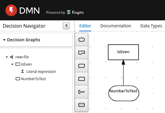
Figure 8.25 – A simple DMN rule
This rule will check whether a number in input is even, returning Yes or No.
The rounded component is a DMN Input Data element, which contains the NumberToTest input variable, while the Is Even ? rectangle component is a DMN Decision containing the algorithm. In this case, if we look in the panel on the left, the component contains a so-called literal expression. By editing the component, we can see this expression:
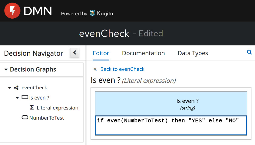
Figure 8.26 – A simple DMN rule
Of course, this is a very simple example expression. In a real-world application, you could have much more complex logic, such as a combination of different expressions, a function, and a decision table. The decision would likely have other components, such as different input, complex types, and reusable decisions.
Let's now extend our reasoning with business workflows.
Business workflows
Business workflows can be seen, conceptually, as an extension of the concept of business rules. By using workflows, indeed, you aim to logically separate the business logic from the implementation and application logic.
While with rules you isolate a decision (which may be simple or complex at will), with workflows you model an entire process. You will still start from a set of information and arrive at a final outcome, but the process will involve a number of different steps and it will usually be passivated every now and then (usually on a database) while waiting for each step to complete.
The steps can be fully automated (such as when calling a REST service or sending a message to a queue or similar things), or simply represent a human task happening outside of our application (such as the signature on a paper document or other manual tasks) and need an explicit confirmation (which may be via email or completing a web form) in order to signal the completion (and let the process continue). So, to keep it simple, while a business rules model represents a single calculation, a business process involves a set of different steps and each decision may go through a set of different paths.
Indeed, one core function of workflows, other than modeling and isolating business processes, is to give insights into the process performance and statistics from both a business and a technical point of view.
Let's suppose that we implement a business process to represent a loan request. You will have a first step for getting the data for the request, including the amount of money requested, the name of the requestor, and their age. You will then most likely have a set of validation, such as a background check of the requestor, verification of their salary, and the history of the payments made by the requestor. Each of these steps can be modeled as an item in a workflow, which can be completed automatically (such as calling an external system asking for information) or by asking an operator (such as sending an email and waiting for the reply). It's a common practice to model some of those steps as business rules, according to what we have seen so far in this chapter.
Let's suppose you have such a system in production. You can then extract the historical data from the past process instances and understand how well your workflow is performing. How many loan requests get approved at the end? How much time do you spend on each task? What's the average age of each requestor?
From this valuable data, the business can get insights to change the process (such as simplifying, changing, or removing some steps), to create different promos (such as a special loan with different interest rates for a specific audience), and so on. This is basically the reason why you want to isolate decisions (whether rules or processes). You now can easily know what's happening in your application and fine-tune such behavior while having a limited impact on the other functionalities.
The most widespread approach to technically model such business processes is to rely on the BPMN notation, which is a standard. Also, as DMN is based on XML, it is human-readable and editable by using graphical tools. For more information on BPMN, please refer to Chapter 3, Common Architecture Design Techniques.
The jBPM project
jBPM is another project under the KIE umbrella, providing a lightweight and extensible engine for running BPMN workflows. Similar to Drools, jBPM can be deployed in many different ways, including embedded in your applications and standalone, and it can rely on many different runtimes (such as JBoss WildFly and Quarkus), implementing both traditional and cloud-native scenarios.
As per the Drools project, jBPM provides some free tools to visualize and edit BPMN files at github.com/kiegroup/kogito-tooling and you can use the online editor on the bpmn.new page.
This is what a simple workflow looks like:
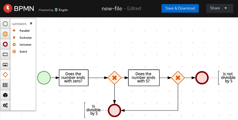
Figure 8.27 – A simple BPMN process
In this simple process, we check the divisibility of a number by 5. There is a start, then a couple of checks (whether the number ends with zero or five), and a logic gateway that leads to an end in both cases: is or is not divisible.
This section completes our overview of business automation. In the next section, we will compare the architectural roles of integration and automation.
Integration versus automation – where to draw the line
A common discussion when designing complex software architectures is where to define the boundary between integration and automation.
After all, there is a bit of overlap: both a business workflow and an integration route can call a number of external systems sequentially or while going through conditions (which may be represented, in both cases, as business rules).
Of course, there is not a fixed answer for every behavior. I personally prefer to avoid polluting the business automation with too many technical integrations (such as connectors for specific uncommon technologies, everything that is not a call to a web service or a message in a queue) and the integration routes with conditions that are dependent on specific business requirements (such as modeling a business process as an integration route). But other than this high-level, common-sense advice, there are a few considerations that can help in understanding whether a particular feature should stay in the automation or integration layer:
- If the flow that represents our use case involves a significant number of human tasks (such as when human interaction is needed), it will likely be a business workflow.
- If you have to deal with technologically driven behavior, such as retries in the case of errors in service calls or other details about the protocols used by the external system, it is most likely something to encapsulate in an integration route.
- If the process has business relevance, so every step is something significant to a business person, who could be interested in the performance of the process (meaning how many processes are stuck in a step, or how much time is needed for a particular path), it is likely to be a business workflow.
- If no passivation is needed, meaning that the majority of instances are straight-through processes, or in other words, a set of steps performed one after the other without needing to be persisted in a data store (waiting for a signal or other events to restart), it is likely an integration route.
That is my personal advice on how to consider whether a particular feature should be in an integration or business automation layer. Indeed, in many cases, you will need a combination of both layers:
- An integration layer is used to encapsulate technical details into interactions with third-party and other external systems (such as databases) and expose such functionalities as a higher-level, composite API (such as a REST service).
- A workflow layer orchestrates the calls to those high-level APIs, adds human tasks (if needed) and processes instance persistence, and in general models business processes and gets metrics and insights on such process execution.
This completes our overview of business automation. In the next section, we will have a look at examples of integration and automation using the aforementioned technologies.
Case studies and examples
In this section, we are going to go on with our payment use case, to see some examples of integration and business automation.
For example purposes, we will use Camel, jBPM, and Drools. Our target runtime will be Quarkus, which we already saw in the previous chapter.
But many of the concepts and implementations are applicable to other runtimes, such as embedded ones (as in using the runtime as a dependency of your Java application), deployed on JBoss WildFly, and deployed on Spring Boot.
Integrating payment capabilities
Our first use case to implement integration is the connection of payment capabilities with a legacy backend. Let's suppose that we have developed our microservices payment application and it is working correctly. A new business requirement is to integrate a legacy platform for settlement purposes (which is a kind of accounting operation done after payments).
It's fairly easy for our core application to call a REST service for this purpose, but the legacy system used for settlement works with .xml files placed in a shared folder. That's a perfect fit for integration: there is no business logic apart from some plumbing to make the two systems talk to each other, and it will be fairly easy to implement with a rich and expressive framework such as Camel.
There are a number of ways to create a Camel project on top of Quarkus. As we saw in the previous chapter, we can create it with the mvn command, or go to the Quarkus website and use a web wizard to download an empty project scaffold.
The dependencies that we are going to use are in the camel-quarkus family. Here are the details:
- camel-quarkus-platform-http is basically a bridge to make the existing HTTP server of the runtime (Quarkus, in our case) usable from Camel.
- camel-quarkus-jackson is the component to marshal POJO to JSON and vice versa.
- camel-quarkus-jacksonxml works on the same concept, but for XML serialization. As we have seen, Jackson is a library that can be used for JSON, XML, and other formats.
- camel-quarkus-file is the default component for reading and writing files.
We have already created a Payment Java class for holding our payment data, in the previous chapter. You can see the fields used in the following code (the rest of the class is getters and setters plus some more boilerplate code):
public class Payment {
private String id;
private Date date;
private String currency;
private String sender;
private String recipient;
private String signature;
private float amount;
...
In order to define a Camel integration route using Java DSL, it's enough to create a class extending EndpointRouteBuilder, as follows (imports are omitted here):
@ApplicationScoped
public class PaymentSettlement extends EndpointRouteBuilder
{
@Override
public void configure() throws Exception {
from(platformHttp("/camel/settlement"))
.unmarshal()
.json(JsonLibrary.Jackson, Payment.class)
.setHeader("PaymentID", simple("${body.id}"))
.marshal()
.jacksonxml()
.to(file("{{settlement.path}}?fileName=
${header.PaymentID}.xml"));
}
}
This simple Java code models an integration route that starts by exposing an HTTP endpoint, unmarshals the requests coming as JSON objects (using the Jackson framework), mapping it to a Java object of the Payment class, sets a header, then marshals the Java object to XML (using Jackson again), and finally writes the XML to a file.
To call the Camel route, we have to post a request to /camel/settlement (http://127.0.0.1:8080/camel/settlement, if we are running locally), which is a JSON representation of the Payment object (as seen in the previous chapter). Here's an example:
{
"id":"1ef43029-f1eb-4dd8-85c4-1c332b69173c",
"date":1616504158091,
"currency":"EUR",
"sender":"[email protected]",
"recipient":"[email protected]",
"signature":"169e8dbf-90b0-4b45-b0f9-97789d66dee7",
"amount":10.0
}
Regarding the Camel route, we already saw a similar flow a couple of sections ago, in the The Camel DSL section, following our first look at the Camel framework, in the The Camel integration framework section. However, there are a couple of things worth noticing:
- There is a setHeader method, which locates the id field from the body of the current message flowing through the Camel route (which is the ID of the payment transaction) and sets it into the PaymentId header so it can be reused later as a name for the .xml file that we are generating. Note that the simple expression language is used, which can be used for navigating the payload (using the dot notation) and express conditions.
- The Quarkus properties (defined according to what we saw in the previous chapter, using the system properties defined in application.properties or in many other ways) are directly accessed and used with double curly brackets. In this case, the file component accesses the {{settlement.path}} variable to set the destination path of the settlement file.
But what if we want to avoid the generation of settlement for an amount of less than 10 €? That's easy. It is enough to implement the filter EIP and basically drop the messages that do not respect the relevant condition:
from(platformHttp("/camel/settlement"))
.unmarshal()
.json(JsonLibrary.Jackson, Payment.class)
.setHeader("PaymentID", simple("${body.id}"))
.setHeader("Amount", simple("${body.amount}"))
.marshal()
.jacksonxml()
.filter(simple("${header.amount} > 10"))
.to(file("{{settlement.path}}?fileName=
${header.PaymentID}.xml"));
As you can see, the Camel component is indeed called filter.
And what if we want to add a different behavior for the two conditions (less than 10 € or more than 10 €)? The EIP here is a content-based router, which can be implemented in Camel using the choice component, like this:
from(platformHttp("/camel/settlement"))
.unmarshal()
.json(JsonLibrary.Jackson, Payment.class)
.setHeader("PaymentID", simple("${body.id}"))
.setHeader("Amount", simple("${body.amount}"))
.marshal()
.jacksonxml()
.choice()
.when(simple("${header.amount} > 10"))
.to(file("{{settlement.path}}?fileName=
${header.PaymentID}.xml"))
.otherwise()
.log("No settlement needed")
.end();
In this case, we are simply logging in the otherwise case, but in the real world, you may consider doing something more (such as writing a different file format or in different storage) and you can also add a number of different when conditions.
More generally, this is just a taste of what Camel can do. In the real world, there are a lot of technology connectors, formats, and patterns, and the routes can be modularized to call each other. On the official Camel website, you can even find a page about mapping between EIP and Camel components. This completes our integration example. Let's now have a look at automation.
Automating customer onboarding
Our payment platform will for sure need a process to onboard customers. It's pretty common to have some actions supporting the creation of profiles for new customers, including validations and the provisioning of customers on many different systems. This is a task that is a perfect fit for business automation.
Indeed, customer onboarding is commonly driven by (changing) business requirements (such as the number of steps for registering a user and facilitating the onboarding of some categories for promotional purposes). Moreover, these kinds of processes may be regulated by laws, and so it may happen that you have different workflows in different geolocations (such as some countries requiring wet signatures on paper needing to be modeled as human tasks) and changing steps with changing regulations over time.
Last but not least, the process of provisioning a user is typically stateful: you will want to have it persisted on a data store for auditing, reporting, and customer experience purposes. It may happen that a customer starts the registration process on a mobile app, then the user continues doing other steps on a computer, then lastly, finalizing it by going to a bank branch.
A workflow will allow this kind of experience (also known as omnichannel) by persisting each step (where needed) and providing a stateful process. Let's start with modeling one single step of the workflow: a business rule modeling the age check of a customer. That's quite easy with DMN and the visual editor provided by the Kogito project (maybe the online one, or a standalone version, as a plugin for an IDE, such as VSCode):

Figure 8.28 – A simple DMN validation rule
This is a very simple rule: using the customer data structure and providing a CheckAge DMN decision. Here is what's inside such a decision:
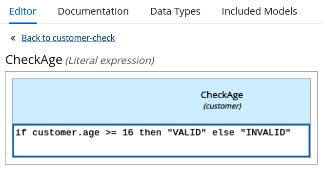
Figure 8.29 – The rule expression
In this example, we are using a very simple Friendly Enough Expression Language (FEEL) expression, checking on the age field of the customer structure. Here is what the structure looks like in the Data Types editor:

Figure 8.30 – The customer data type
In the sources of this example, you can also find the POJO representing the same structure (and it is interoperable with it). In order to invoke this rule, we need to post this REST request in JSON:
POST http://localhost:8080/customer-check HTTP/1.1
content-type: application/json
{
"customer":{
"name":"Giuseppe",
"surname":"Bonocore",
"age":37,
"taxCode":"dads213213fasfasf"
}
}
Here, the Kogito engine will reply with VALID or INVALID. This is, of course, pretty useful: you can easily create decision services providing business rules (usually more complex than the one seen in this example) and use them in your project. But there is more: this rule can become one step in a more complex workflow.
Let's imagine a very simple prototype of a customer onboarding process: you have the start of the process, a preparation step (which may include sending a request to a CRM or other systems), and the evaluation of the age of the customer (by using the DMN rule that we have just seen). If the age is INVALID, you may want to have some special handling (such as asking for the permission of a parent). We did exactly that in this simple BPMN workflow:

Figure 8.31 – The customer data type
In this example, the Evaluate Customer step is using our DMN rule, while the other steps, for example, purposes, are simple script tasks printing the information on the console (using a System.out call). Of course, you may want to have different kinds of tasks here, such as REST calls to external services, sending messages, or human tasks. Whatever your implementation is, you can trigger the workflow with a REST request, such as the following:
POST http://localhost:8080/customer_onboarding HTTP/1.1
content-type: application/json
{
"customer":{
"name":"Giuseppe",
"surname":"Bonocore",
"age":37,
"taxCode":"dads213213fasfasf"
}
}
Take into account that in this simple example, we have not configured a persistence layer, nor defined tasks requiring passivation of the process instance. If this is needed, you can easily do it by adding some configurations (such as in the application.properties file). Once you have a process requiring and using persistence, you can then query the Kogito engine, asking for the status of encapsulated (or even completed) process instances, the list of pending tasks, and so on (like you could do in a typical BPMN workflow engine). This completes our examples for this chapter.
Summary
In this chapter, we have looked at a lot of technologies, completing the middleware overview that we started in the last chapter. You have also learned what an ESB is (including connectors, patterns, and data formats).
We have looked at the enterprise integration patterns and the Camel library, which is an implementation of enterprise integration patterns. We have also looked at messaging systems to support the concept of integration in asynchronous scenarios. We then shifted our view of process automation by digging into business rules and business workflows and having a glimpse at Kogito, which is a complete business automation engine running on Quarkus.
After this chapter, you should be able to understand the basics of enterprise integration, including messaging capabilities. We have also seen what business automation is, including workflows and rules, and how to differentiate what should stay in an integration layer from what should stay in a business automation layer. By using some open source libraries, we have gone through a couple of examples of implementing these concepts in Java.
In the next chapter, we will see how to design and implement a modern distributed application by applying cloud-native architecture recommended practices.
Further reading
- The arc42 official website: https://arc42.org/
- Gregor Hohpe, Bobby Woolf, Enterprise Integration Patterns (www.enterpriseintegrationpatterns.com)
- Enterprise Integration Patterns, by Gregor Hohpe and Bobby Woolf, published by Pearson Education (2012)
- Apache Software Foundation: The Apache Camel project (camel.apache.org)
- Apache Software Foundation: The Apache Camel project – mapping to EIP (camel.apache.org/components/latest/eips/enterprise-integration-patterns.html)
- The official XML website (XML.org)
- The official JSON website (JSON.org)
- The Google Protobuf Java tutorial (developers.google.com/protocol-buffers/docs/javatutorial)
- The official gRPC website (grpc.io)
- The KIE project, including Drools, jBPM, and more (www.kiegroup.org)
- The Kogito project, providing business automation on Quarkus (kogito.kie.org)