
Chapter 7: Visual Effects with Particle Systems and Visual Effect Graph
In this chapter, we will continue learning about visual effects we can use for our game. We will be discussing particle systems, which we can use to simulate fire, waterfalls, smoke, and all kinds of fluids. Also, we will look at the two Unity particle systems for creating these kinds of effects, Shuriken and Visual Effect Graph, with the latter being more powerful than the first, but requiring more hardware.
In this chapter, we will cover the following topics:
- Introduction to particle systems
- Creating fluid simulations
- Creating complex simulations with Visual Effect Graph
Introduction to particle systems
All the graphics and effects we have created so far use static meshes, 3D models that can't be skewed, bent, or deformed in any way. Fluids such as fire and smoke clearly can't be represented using this kind of mesh. However, we can simulate these effects with a combination of static meshes, and this is where particle systems are useful.
Particle systems are objects that emit and animate lots of particles or billboards, which are simple quad meshes that face the camera. Each particle is a static mesh, but rendering, animating, and combining lots of them can generate the illusion of a fluid. In the following figure, on the left, you can see a smoke effect using particle systems, while on the right, you can see the Wireframe view of the same particles. There, you can see the quads that create the illusion of smoke, which is done by applying a smoke texture to each of the particles and animating them so that they spawn at the bottom and move up in random directions:
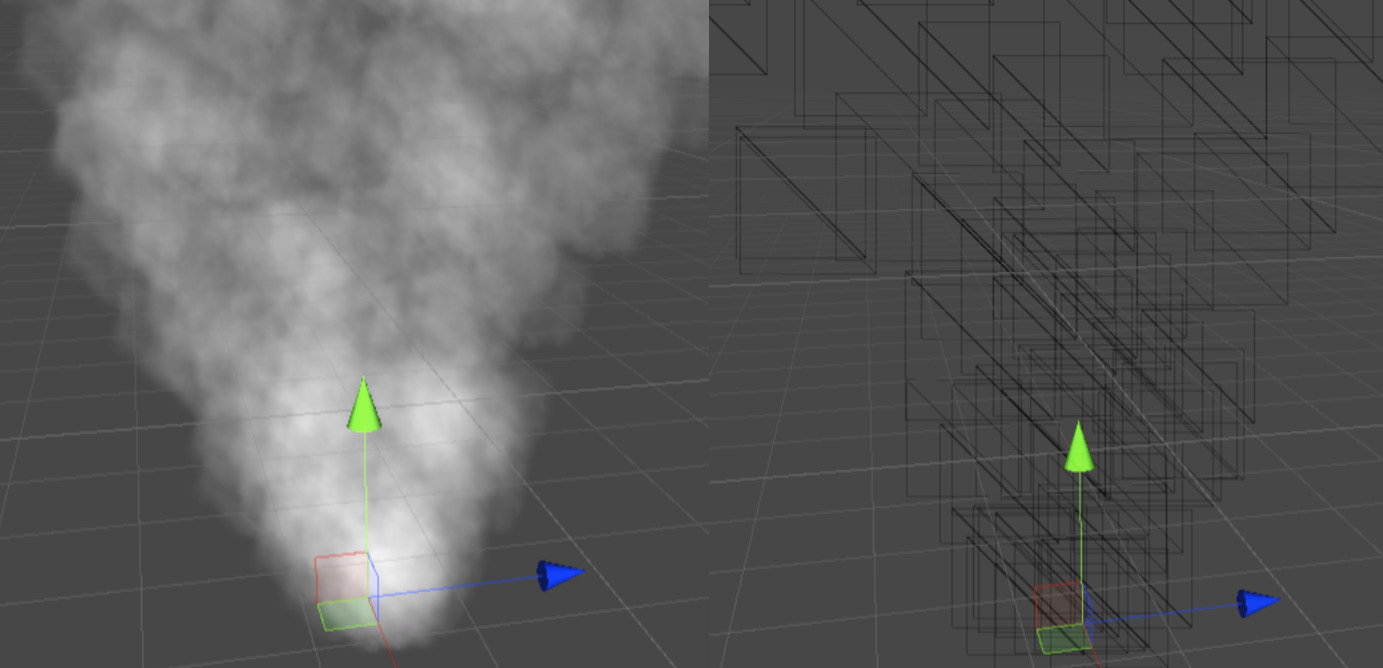
Figure 7.1 – Left, a smoke particle system; right, the wireframe of the same system
In this section, we will cover the following concepts related to particles:
- Creating a basic particle system
- Using advanced modules
Let's start by discussing how to create our very first particle system.
Creating a basic particle system
To illustrate how to create a particle system, let's create an explosion effect. The idea is to spawn lots of particles at once and spread them in all directions. Let's start by creating a particle system and configuring the basic settings it provides to change its default behavior. To do so, follow these steps:
- Select the GameObject | Effects | Particle System option:
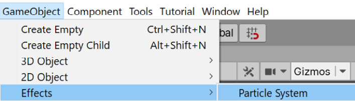
Figure 7.2 – Particle System option
- You can see the effect in the following screenshot. The default behavior is a column of particles going up, similar to the smoke effect shown previously. Let's change that:
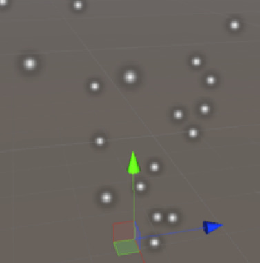
Figure 7.3 – Default appearance of the particle system
- Click the created object in the scene and look at the Inspector window.
- Open the Shape section by clicking on the title. Here, you can specify the particle emitter shape where the particles are going to be spawned.
- Change the Shape property to Sphere. Now, the particles should move in all possible directions instead of following the default cone:
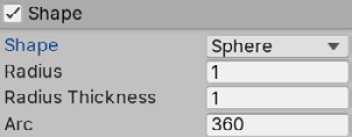
Figure 7.4 – Shape properties
- In the particle system module (usually known as Main), set Start Speed to 10. This will make the particles move faster.
- In the same module, set Start Lifetime to 0.5. This specifies how long a particle will live. In this case, we have given a lifetime of half a second. In combination with the speed (10 meters per second), this makes the particles disappear after moving 5 meters:

Figure 7.5 – Main Particle System module
- Open the Emission module and set Rate over Time to 0. This property specifies how many particles will be emitted per second, but for an explosion, we need a burst of particles, so we won't emit particles constantly over time in this case.
- In the Bursts list, click the + button at the bottom. Then, in the created item in the list, set the count column to 100:

Figure 7.6 – Emission module
- In the Main module (the one titled Particle System), set Duration to 1 and uncheck Looping. In our case, the explosion won't repeat constantly; we just need one explosion:
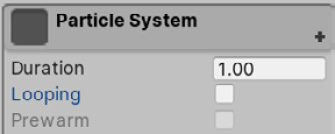
Figure 7.7 – Looping checkbox
- Now that the particle isn't looping, you need to manually hit the Play button in the Particle Effect window, in the bottom-right part of the Scene view, to see the system:

Figure 7.8 – Particle system playback controls
- Set Stop Action to Destroy. This will destroy the object when the Duration time has passed. This will work when you are running the game, so you can safely use this configuration while editing your scene:
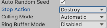
Figure 7.9 – Stop Action set to Destroy
- Set Start Size of the Main module to 3. This will make the particles bigger so that they seem denser:
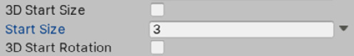
Figure 7.10 – Particle system Start Size
- Click on the down-pointing arrow to the right of the Start Rotation property of the Main module and select Random Between Two Constants.
- Set Start Rotation to 0 and 360 for the two input values that appeared after the previous step. This allows us to give the particles a random rotation when they spawn to make them look slightly different from each other:

Figure 7.11 – Random Start Rotation
- Now, the particles behave as expected, but they don't look as expected. Let's change that. Create a new Material by clicking on the + icon in the Project view and selecting Material. Call it Explosion.
- Set its shader to Universal Render Pipeline/Particles/Unlit. This is a special shader that is used to apply a texture to the Shuriken particle system:

Figure 7.12 – Particle system material shader
- Download a smoke particle texture from the internet or Unity's Asset Store. In this case, it is important to download one with a black background; ignore the others:

Figure 7.13 – Smoke particle texture
- Set this texture as the Base Map of the material.
- Set Surface Type to Transparent and Blending Mode to Additive. Doing this will make the particles blend with each other, instead of being drawn over each other, to simulate a big mass of smoke instead of individual smoke puffs. We are using Additive mode because our texture has a black background and because we want to create a lighting effect (the explosion will brighten the scene):

Figure 7.14 – Surface Options for particles
- Drag your material to the Material property of the Renderer module:

Figure 7.15 – Particle material settings
- Now, your system should look like this:
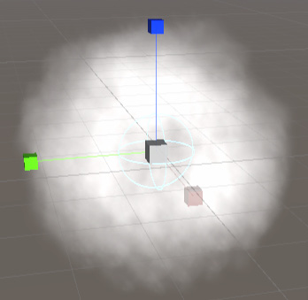
Figure 7.16 – The result of the previous settings
In the previous steps, we have changed how the particles or billboards will spawn (using the Emission module), in which direction they will move (using the Shape module), how fast they will move, how long they will last, how big they will be (using the Main module), and what they will look like (using the Renderer module). Creating particle systems is a simple case of configuring their different settings. Of course, doing this properly is an art on its own; it requires creativity and knowledge of how to use all the settings and configurations they provide. So, to increase our configuration toolbox, let's discuss some advanced modules.
Using advanced modules
Our system looks nice, but we can improve it a lot, so let's enable some new modules to increase its quality:
- Check the checkbox on the left of the Color over Lifetime module to enable it:
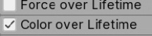
Figure 7.17 – Enabling the Color over Lifetime module
- Open the module by clicking on the title. Then, click the white bar on the right of the Color property. This will open the gradient editor.
- Click slightly to the right of the top-left white marker in the bar to create a new marker. Also, click slightly to the left of the top-right white marker to create the fourth marker. These markers will allow us to specify the transparency of the particles during its lifetime:
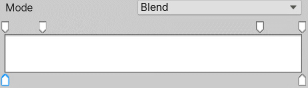
Figure 7.18 – Color over Lifetime in gradient editor
- If you have created any unwanted markers, just drag them outside the window to remove them.
- Click on the top-left marker (not the one we created – the one that was already there) and set the Alpha slider at the bottom to 0. Do the same with the top-right marker, as shown in the following screenshot. Now, you should see the particles fading away instead of popping out of existence when the explosion is finishing:
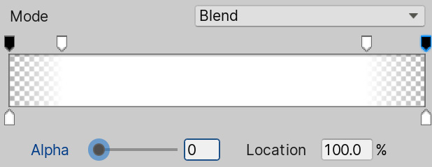
Figure 7.19 – Fading in and fading out the gradient
- Enable the Limit Velocity over Lifetime module by clicking on its checkbox.
- Set the Dampen setting to 0.1. This will make the particles slowly stop instead of continuing to move:

Figure 7.20 – Dampening the velocity to make the particles stop
- Enable Rotation over Lifetime and set Angular Velocity between -90 and 90. Remember that you should set the value in Random Between Two Constants by clicking on the down-pointing arrow to the right of the property. Now, the particles should rotate slightly during their lifetimes to simulate more motion:
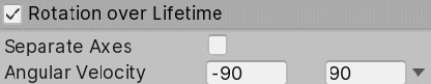
Figure 7.21 – Random rotation velocity
Some of these effects will be very subtle, given the short lifetime we set in the Main Module when we just created the particle. Feel free to increase the lifetime value to see those effects in more detail, but note that this could lead to an excessive number of particles if you spawn them frequently, thereby reducing performance. Just be wary about how they impact your performance when tweaking those values.
As you can see, there are lots of extra modules that can be enabled and disabled to add layers of behavior on top of the existing ones, so again, use them creatively to create all kinds of effects. Remember that you can create Prefabs of these systems to replicate them all over your scene. I also recommend searching for and downloading particle effects from the Asset Store to see how other people have used the same system to create amazing effects. That is the best way to learn how to create them – viewing a variety of different systems – and that is actually what we are going to do in the next section: create more systems!
Creating fluid simulations
As we mentioned previously, the best way to learn how to create particle systems is to keep looking for already-created particle systems, and then explore how people have used various system settings to create completely different simulations.
In this section, we will learn how to create the following effects using particle systems:
- A waterfall effect
- A bonfire effect
Let's start with the simplest one: the waterfall effect.
Creating a waterfall effect
In order to do this, follow these steps:
- Create a new particle system (GameObject | Effects | Particle System).
- Set Shape to Edge and its Radius to 5 in the Shape module. This will make the particles spawn along a line of emission:
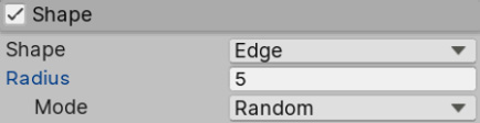
Figure 7.22 – Edge shape
- Set Rate over Lifetime of the Emission module to 50.
- Set Start Size of the Main module to 3 and Start Lifetime to 3:
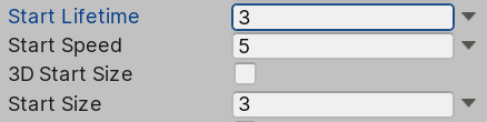
Figure 7.23 – Main module settings
- Set Gravity Modifier of the Main module to 0.5. This will make the particles fall:
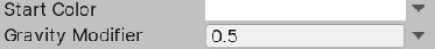
Figure 7.24 – Gravity Modifier in the Main module
- Use the same Explosion material we created previously for this system:

Figure 7.25 – Explosion particle material
- Enable Color Over Lifetime and open the Gradient editor.
- Click the bottom-right marker. This time, you should see a Color picker instead of an alpha slider. The top markers allow you to change the transparency over time, while the bottom ones change the color of the particles over time. Set a light blue color in this marker:

Figure 7.26 – White to light blue gradient
As a challenge, I suggest that you add a little particle system where this one ends to create some water splashes, simulating the water colliding with a lake at the bottom. Now, we can add this particle system to one of the hills of our scene to decorate it, as shown in the following screenshot. I have adjusted the system a little bit so that it looks better in this scenario. I challenge you to tweak it by yourself to make it look like this:
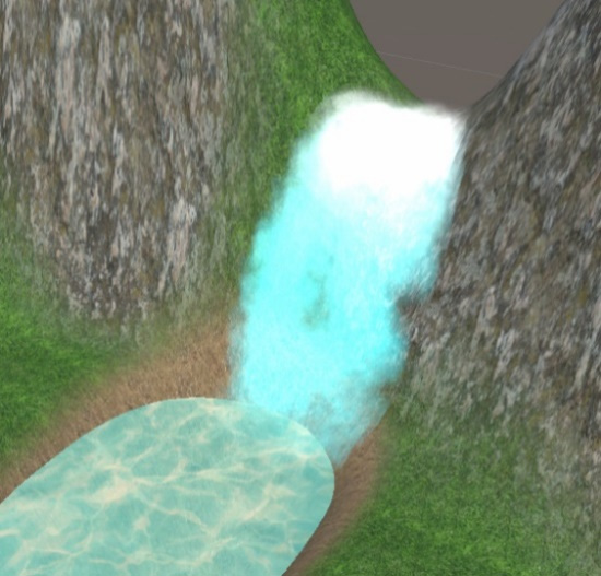
Figure 7.27 – The waterfall particle system being applied to our current scene
Now, let's create another effect: a bonfire.
Creating a bonfire effect
In order to create this, do the following:
- Create a particle system (GameObject | Effects | Particle System).
- Look for a Fire Particle Texture Sheet texture on the internet or the Asset Store. This kind of texture should look like a grid of different flame textures. The idea is to apply a flame animation to our particles, which swaps all those mini textures:

Figure 7.28 – Particles texture sprite sheet
- Create a particle material that uses the Univeral Render Pipeline/Particles/Unlit shader.
- Set the flame's sprite sheet texture as the Base Map.
- Set the color to the right of the Base Map to white.
- Set this material as the particle material. Remember to set Surface Type to Transparent and Blending Mode to Additive:
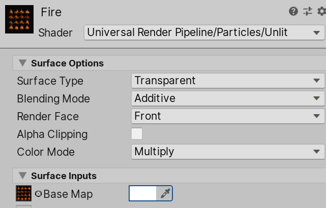
Figure 7.29 – A material with a particle sprite sheet
- Enable the Texture Sheet Animation module and set the Tiles property according to your fire sheet. In my case, I have a grid of 4x4 sprites, so I put 4 in X and 4 in Y. After this, you should see the particles swapping textures:

Figure 7.30 – Enabling Texture Sheet Animation
- Set Start Speed to 0 and Start Size to 1.5 in the Main module.
- Set Radius to 0.5 in Shape.
- Create a second particle system and make it a child of the fire system:

Figure 7.31 – Parenting particle systems
- Apply the Explosion material from the explosion example.
- Set Angle to 0 and Radius to 0.5 in the Shape module.
The system should look like this:
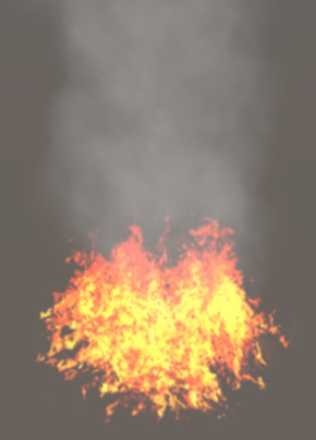
Figure 7.32 – Result of combining the fire and smoke particle systems
As you can see, you can combine several particle systems to create a single effect. Take care when doing this because it's easy to emit too many particles and affect the game's performance. Particles are not cheap and may cause a reduction in the game's Frames Per Second (FPS) if you are not cautious when using them.
So far, we have explored one of the Unity systems that you can use to create these kinds of effects, and while this system is enough for most situations, Unity recently released a new one that can generate more complex effects, called Visual Effect Graph. Let's learn how to use it and see how it differs from Shuriken.
Creating complex simulations with Visual Effect Graph
The particle system we have used so far is called Shuriken, and it handles all calculations in the CPU. This has pros and cons. A pro is that it can run on all possible devices that Unity supports, regardless of their capabilities (all of them have CPUs), but a con is that we can exceed CPU capabilities easily if we are not cautious regarding the number of particles we emit. Modern games require more complex particle systems to generate believable effects, and this kind of CPU-based particle system solution has started to reach its limit. This is where Visual Effect Graph comes in:

Figure 7.33 – Left, a massive particle system; right, an example of a Visual Effect Graph
Visual Effect Graph is a GPU-based particle system solution, meaning that the system is executed in the video card instead of the CPU. That's because video cards are far more efficient at executing lots and lots of little simulations, like the ones each particle of a system needs, so we can reach far higher orders of magnitude in the number of particles with the GPU than we can with the CPU. The con here is that we need a fairly modern GPU that has compute shader capabilities to support this system, so we will exclude certain target platforms using this system (forget about most mobile phones), so use it if your target platform supports it (mid- to high-end PCs, consoles, and some high-end phones).
In this section, we will discuss the following concepts of Visual Effect Graph:
- Installing Visual Effect Graph
- Creating and analyzing a Visual Effect Graph
- Creating a rain effect
Let's start by learning how we can add support for Visual Effect Graph in our project.
Installing Visual Effect Graph
So far, we have used lots of Unity features that were already installed in our project, but Unity can be extended with a myriad of plugins, both official and third-party ones. Visual Effect Graph is one of those features that needs to be independently installed if you are using Universal Render Pipeline (URP). We can do that using Package Manager, a Unity window dedicated to managing official Unity plugins.
Something to think about when you are installing those packages is that each package or plugin has its own version, independent of the Unity version. This means that you can have Unity 2021.1 installed, but Visual Effect Graph 11.0.0 or 11.1.0, or whatever version you want, and you can update the package to a newer version without upgrading Unity. This is important because some versions of these packages require a minimum version of Unity. Moreover, some packages depend on other packages – specific versions of those packages – so we need to ensure we have the correct versions of every package to ensure we have compatibility. To be clear, the dependencies of a package are installed automatically, but sometimes, we can install them separately. So, in that scenario, we need to check the required version. It sounds complicated, but it is simpler than it sounds.
At the time of writing this book, to get Visual Effect Graph working properly, we need version 11.0.0, and also we need to have Universal RP version 11.0.0. Yes, Universal RP is another feature you can install using Package Manager, but since we created the project using the Universal RP template, it was already installed for us with the proper version. However, this may not always be true, so we must check that. With that in mind, let's install Visual Effect Graph, as follows:
- In the top menu of Unity, go to Window | Package Manager:
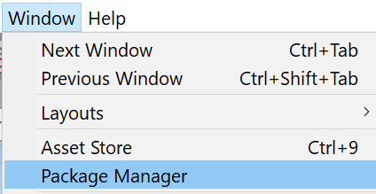
Figure 7.34 – Package Manager location
- Remember to ensure Package Manager is in Unity Registry mode so that you can see Unity's official packages list:
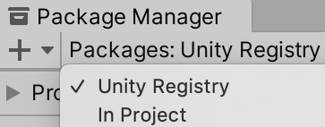
Figure 7.35 Package Manager – Unity Registry mode
- From the left column, locate Universal RP and check whether it says 11.0.0 or higher to the right. If it does, jump to step 6. Remember, though, that a higher version may look different or have different steps you must follow to use it than the ones displayed in this chapter:

Figure 7.36 – Universal RP package
- If you don't have version 11.0.0 or higher, click on the right-pointing arrow to the left to display a list of all possible versions to install. Locate 11.0.0 and click it. In my case, it says currently installed as I have the proper version and there are no others available for Unity 2021:

Figure 7.37 – Package version selector
- Click on the Update to 11.0.0 button in the bottom-right corner of the window and wait for the package to update.
- Look for the Visual Effect Graph package on the left-hand side of the window. As you did with Universal RP, make sure you select version 11.0.0 or higher (whichever is closest):

Figure 7.38 – Visual Effect Graph package
- Click the Install button on the bottom right of the window and wait for the package to install:
Figure 7.39 – Install button
- Sometimes, it is recommended to restart Unity after installing these packages, so save your changes and restart Unity.
Now that we have installed Visual Effect Graph, let's create our first particle system using it.
Creating and analyzing a Visual Effect Graph
The philosophy behind creating a particle system using Visual Effect Graph is similar to the regular Particle System. We will chain and configure modules as part of the behavior of the particles, each module adding some specific behavior. However, the way we do this is very different than what we usually do with Shuriken. First, we need to create a Visual Effect Graph, an asset that will contain all the modules and configurations, and then make a GameObject play the graph. Let's do that by performing the following steps:
- In the Project window, click on the + button and look for Visual Effects | Visual Effect Graph:

Figure 7.40 – Visual Effect Graph
- Create an empty GameObject using the Game Object | Create Empty option:

Figure 7.41 – Empty GameObject creation
- Select the created object and look at the Inspector window.
- Using the Add Component search bar, look for the Visual Effect component and click on it to add it to the object:
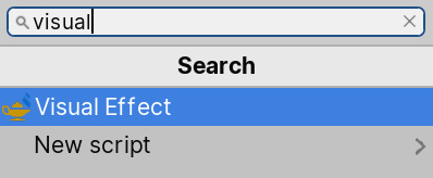
Figure 7.42 – Adding a component to Visual Effect Graph
- Drag the Visual Effect asset we created to the Asset Template property of the Visual Effect component in our GameObject:

Figure 7.43 – Visual Effect using the previously created Visual Effect asset
- You should see clock particles being emitted from our object:
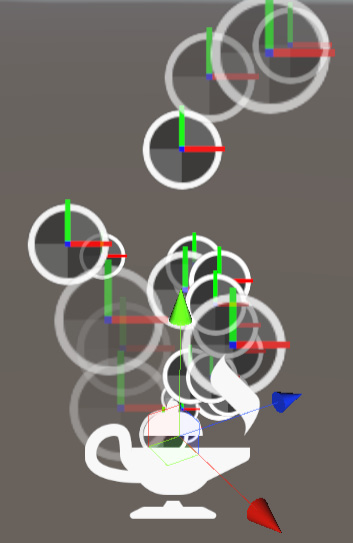
Figure 7.44 – Default Visual Effect Asset results
Now that we have a base effect, let's create something that requires a lot of particles, such as dense rain. Before doing so, we will explore some core concepts of Visual Effect Graph. If you double-click the Visual Effect asset, you will see the following editor:

Figure 7.45 – Visual Effect Graph editor window
This window is composed of several interconnected nodes, generating a flow of actions to be executed. As with Shader Graph, you can navigate this window by holding down the Alt key (Option on Mac) and dragging over the empty areas of the graph with the mouse. At first, it seems similar to Shader Graph, but it works a little bit differently, so let's study each section of the default graph.
The first area to explore is the dotted one that contains three nodes. This is what Unity calls a System. A System is a set of nodes that defines how a particle will behave, and you can have as many as you want, which is the equivalent of having several particle system objects. Each System is composed of Contexts, the nodes inside the dotted area, and in this case, we have Initialize Particle, Update Particle, and Output Particle Quad. Each Context represents a different stage of the particle system's logic flow, so let's define what each context in our graph does:
- Initialize Particle: This defines the initial data of each emitted particle, such as position, color, speed, and size. It is similar to the Start properties in the Main module of the particle system we saw at the beginning of this chapter. The logic in this node will only execute when a new particle is emitted.
- Update Particle: Here, we can apply modifications to the data of the living particles. We can change particle data such as the current velocity or size of all the frames. This is similar to the Over Time nodes of the previous particle system.
- Output Particle Quad: This Context will be executed when the particle needs to be rendered. It will read the particle data to see where to render, how to render, which texture and color to use, and different visual settings. This is similar to the Renderer module of the previous particle system.
Inside each Context, apart from some base configurations, we can add Blocks. Each Block is an action that will be executed in the context. We have actions that can be executed in any Context and then some specific Context actions. As an example, we can use an Add Position Block in the Initialize Particle Context to move the initial particle position, but if we use the same Block in the Update Particle Context, it will move the particle constantly. So, basically, Contexts are different situations that occur in the life of the particle, and Blocks are actions that are executed in those situations:

Figure 7.46 – A Set Velocity Random block inside the Initialize Particle context. This sets the initial velocity of a particle
Also, we can have Standalone Contexts, which are Contexts outside systems, such as Spawn. This Context is responsible for telling the System that a new particle needs to be created. We can add Blocks to specify when the context will tell the system to create the particle, such as at a fixed rate over time and bursts. The idea is that Spawn will create particles according to its blocks, while a System is responsible for initializing, updating, and rendering each of them, again, according to the blocks we set up inside each of those Contexts.
So, we can see that there are lots of similarities with Shuriken, but the way we create a system here is quite different. Let's reinforce this by creating a rain effect, which will require lots of particles. This is a nice use case for Visual Effect Graph.
Creating a rain effect
To create this effect, do the following:
- Set the Capacity property of the Initialize Particle Context to 10000:
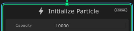
Figure 7.47 – Initialize Particle context
- Set Rate of Constant Spawn Rate of the Spawn context to 10000:
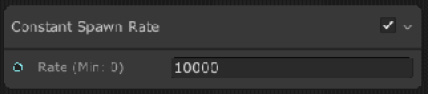
Figure 7.48 – Constant Spawn Rate block
- Set the A and B properties to (0, -50, 0) and (0, -75, 0) in the Set Velocity Random Block in Initialize Particle Contexts, respectively. This will set a random velocity pointing downward for our particles:

Figure 7.49 – Set Velocity Random block
- Right-click the Initialize Particle title and select Create Block.
- Search for the Set Position Random block and click on it:
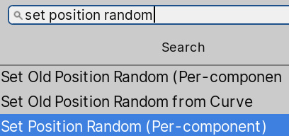
Figure 7.50 – Adding blocks
- Set the A and B properties of the Set Position Random block to (-50 , 0, -50) and (50, 0, 50), respectively. This will define an initial area where we will randomly spawn the particle.
- Click the arrow to the left of the Bounds property of the Initialize Particle Block to display its properties. Then, set Center and Size to (0, -12.5, 0) and (100, 25, 100), respectively. This will define the area where the particles should live. Particles can move outside this area, but this is important for the system to work properly (search for Frustum Culling on the internet for more information):
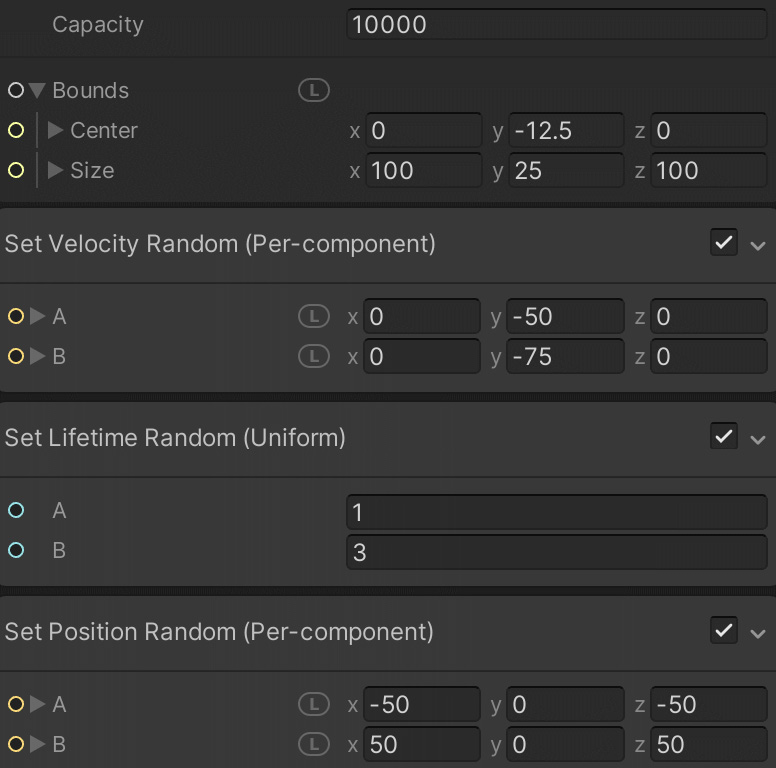
Figure 7.51 – Configuring blocks
- Select the GameObject that is executing the system. Then, in the bottom-right window in the Scene view, check the Show Bounds checkbox to see the previously defined Bounds:

Figure 7.52 – Visual Effect Playback controls
- Set the object's position so that it covers the whole base area. In my case, the position is (100, 37, 100). Remember that you need to change Position of the Transform component for this:
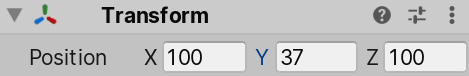
Figure 7.53 – Setting a transform position
- Set the A and B properties of the Set Lifetime Random Block in Initialize Particle to 0.5. This will make the particles have a shorter lifetime, ensuring that they are always inside the bounds:

Figure 7.54 – Set Lifetime Random block
- Change the Main Texture property of the Output Particle Quad Context to another texture. In this case, the previously downloaded smoke texture can work here, even though it's not water, because we will modify its appearance in a moment. Also, you can try to download a water droplet texture if you so wish:

Figure 7.55 – VFX Graph Main Texture
- Set Blend Mode of the Output Particle Quad Context to Additive:
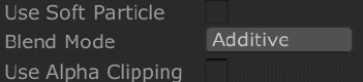
Figure 7.56 – Additive mode of the VFX Graph
- If you can't see the changes being applied, click the Compile button in the top-left corner of the window. Also, you can save your changes using Ctrl + S (Command + S on Mac):
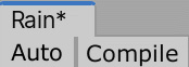
Figure 7.57 – VFX Asset Saving controls
- We need to stretch our particles a little bit so that they look like actual raindrops instead of falling balls. Before accomplishing that, first, we need to change the orientation of our particles so that they don't point at the camera all the time. To do this, right-click on Orient Block in the Output Particle Quad Context and select Delete (or press Del on Windows or Command + Backspace on Mac):
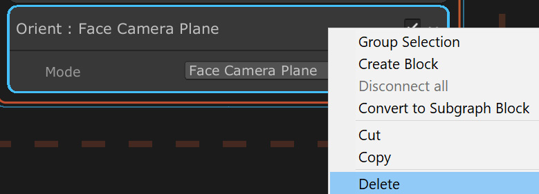
Figure 7.58 – Deleting a block
- We want to stretch our particles according to their velocity direction. Another thing we must do before actually doing that is select the title of the Output Particle Quad context and hit the space bar to look for a block to add. In this case, we need to search for and add the Orient Along Velocity block (right-click on the Output Particle Quad title and then click on Create Block).
- Add a Set Scale Block to the Initialize Particle Context and set the Scale property to (0.25, 1.5, 0.25). This will stretch the particles so that they look like falling drops:
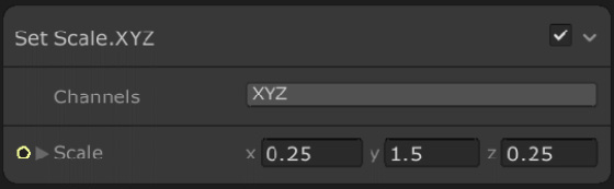
Figure 7.59 – Set Scale block
- Click the Compile button in the top-left window again to see the changes. Your system should look like this:
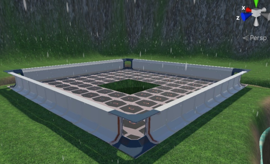
Figure 7.60 – Rain results
From here, you can experiment by adding and removing Blocks from the Contexts as you wish. Again, I recommend that you look for already-created Visual Effect Graphs to find ideas for other systems. Actually, you can get ideas for Visual Effect Graph by looking at effects made in Shuriken and using the analogous blocks. Also, I recommend that you look at the Visual Effect Graph documentation (https://docs.unity3d.com/Packages/[email protected]/manual/index.html) to learn more about this system. You can also access the documentation of any Unity package by clicking the View documentation link in Package Manager while the package is selected:
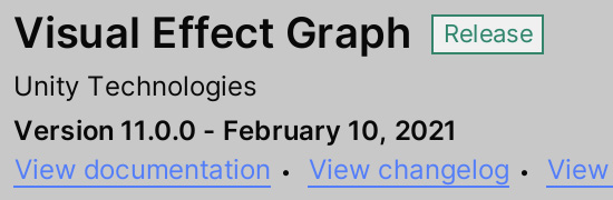
Figure 7.61 – Package Manager documentation link
Now, let's summarize this chapter.
Summary
In this chapter, we discussed two different ways of creating particle systems; that is, using Shuriken and Visual Effect Graph. We used them to simulate different fluid phenomena, such as fire, a waterfall, smoke, and rain. The idea is to combine particle systems with meshes to generate all the props that are needed for your scene. Also, as you can imagine, creating these kinds of effects professionally requires you to go deeper. If you want to dedicate yourself to this (another part of the job of a Technical Artist), you will need to learn how to create your own particle textures to get the exact look and feel you want, code scripts that control certain aspects of the systems, and several other aspects of particle creation. Again, that is outside the scope of this book.
Now that we have some rain in our scene, we can see that the sky and the lighting in the scene don't reflect a rainy day. We'll fix this in the next chapter!