In the previous chapters we discussed the static removal of design errors, structure and use of simulators, and test bench creation. With these components in place, we are ready to simulate designs. The challenge in simulation is to uncover as many bugs as possible within a realistic time frame. To uncover all bugs, one can exhaustively enumerate all possible input patterns and internal states. However, this is seldom feasible in practice. In the following discussion, we will compute an upper bound on the number of input patterns to test exhaustively a sequential circuit having s states. A sequential circuit is completely tested or verified if all of its reachable states are visited from an initial state, and all transitions from that state are verified. So, the first step is to derive an input that drives the circuit from an initial state to any of the s states. There are S such inputs, one for each state. Next, all transitions from that state need to be tested, and there are, at most, R transitions. R is the number of possible inputs. Therefore, an upper bound for the number of inputs is SR. If the circuit has N FFs and M inputs, then S = 2N and R = 2M, and the number of input patterns becomes 2(M+N), which prohibits any practical attempt to verify exhaustively any useful design.
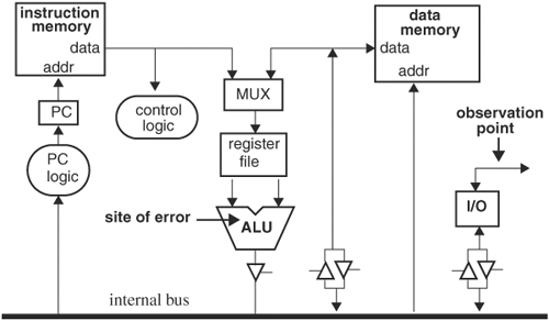
In this chapter we discuss how a design should be simulated over a well-selected subset of all inputs in a systematic manner to achieve a reasonably high level of confidence that the design is correct. With regard to deriving a well-selected subset of input, we discuss test plans and test scenarios, which aid verification engineers in determining corner cases and in enumerating functionality. Because only a subset of all possible inputs is simulated, a measure of quality of the input subset, or of the confidence level of the simulations, is required. We address the issue of simulation quality by discussing several types of coverage measures. Test plans, test scenarios, and coverage can be regarded as methods of search or exploring the input space of the design. After input space exploration is considered, we focus on output space—namely, detecting errors. Detecting errors by comparing a design or a module’s primary outputs with the desired responses may not be the most efficient, because any internal error will have to be propagated to a primary output to be detected, and there can be many cycles after its occurrence. As an example, consider the architecture in Figure 5.1 of a simplified CPU design. If only the I/O port is monitored, marked as the observation point, and we assume that an error in the ALU occurs, then the error is detected only when the I/O block is activated to output data from the internal bus, and the ALU is driving the bus. It is likely that the error in the ALU is stored in data memory or the register file, gets used in later operations, and manifests, if at all, in a totally different form at the I/O port many cycles later. This latency makes debugging difficult, because the designer needs to dump out signals in a time window covering the moment the error originates and trace back through the many cycles. It is also possible that the error will never make it to the I/O port and thus will go undetected.
One approach to reducing bug incubation is to enhance the design’s observability to detect errors as soon as they surface. For example, observation points can be added to the output of the ALU, instruction and data memory data and address lines, control logic, program counter (PC) logic, and the register files. Then, when the error occurs in the ALU, it will be caught immediately. In this chapter we will look at a methodology to enhance systematically a design’s observability by using assertion technology.
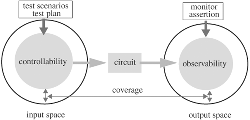
We will address the bug-hunting process in three stages: enumerating input possibilities with test plans, enhancing output observability with assertions, and bridging the gap between exhaustive search and practical execution with coverage measures, as illustrated in Figure 5.2.
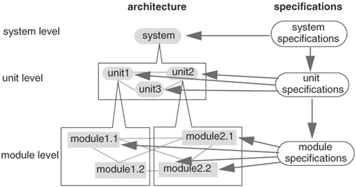
Directly verifying a large system can be difficult for a number of reasons: verification tool capacity limitation, long runtime, and limited controllability and observability. Therefore, a larger system needs to be decomposed into smaller subsystems, which may be decomposed recursively until their sizes are manageable by verification tools. Decomposition can be based on the organization of the design architecture. For instance, a CPU can be decomposed into an instruction prefetcher, an instruction dispatcher, an integer unit, an FPU, an MMU, a cache, a testability structure, and an I/O unit. Furthermore, decomposition can be accomplished at multiple levels. A typical hierarchy includes the system level, unit level, and module level. That is, a system is decomposed into an interconnection of units, each of which is further decomposed into an interconnection of modules. To verify lower level components, their specifications or functionality are derived from those of higher level components. At the top level, the functionality of the overall system is extracted from specifications independent of the implementation architecture. However, the functionality for lower level components is dependent on both the overall specifications and the implementation architecture. The functionality of lower level components working together as determined by the implementation architecture, must accomplish the higher level functionality. Therefore, to verify the overall system specifications, two steps are required. The first step verifies that the units or modules meet their specifications. The second step verifies that the architecture, comprised of the units and modules, as a whole meets the overall specification. The concept of hierarchical verification—structural and functional decomposition—is illustrated in Figure 5.3.
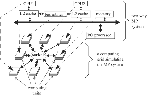
The design under verification at the system level can be the entire chip, a connection of multiple chips, or a board. Because of the complexity at this level, hardware simulators are often used. If software simulators are used, multiple threads or multiple parallel simulators are run concurrently over a network of computers (in other words, a computing grid or computer farm), with each thread or simulator verifying a part of the system. A diagram of a computing grid is shown in Figure 5.4. The two-way processor system with look-through L2 caches is mapped to the computing grid, where each computing unit simulates a unit of the two-way processor system. The dashed arrows denote the mapping from the design units to the computing units. The computing units communicate with each other through TCP/IP sockets.
Two areas of verification are addressed at the system level: (1) verifying interconnections of the subsystems that make up the system and (2) verifying the complete system at the level of implementation. For the first area, the units are assumed to have been verified, and thus they are often modeled at a high level of abstraction (for example, functional models). For example, the CPUs can be replaced by C programs called ISSs. The goal is to demonstrate that the units were constructed to achieve the design objectives of the system. For the second area of verification, all units of the system retain their implementation details (such as RTL), and the entire system is simulated using a computing grid or a hardware simulator. The advantage of this approach is the added confidence that comes from not relying on the functional model, which comes at the expense of high complexity and slow runtime.
With system-level simulation, because the entire system is self-contained, stimuli can be application programs loaded in the system’s memory or can come from the I/O ports when the system is embedded in an application environment. For instance, if the system is a microprocessor, the stimulus can be a compiled program loaded into instruction memory.
To generate test scenarios for system verification, a typical approach is to “benchmark” representative applications and run the benchmarks on the system. Choose benchmarks that represent normal as well as abnormal operations, just to test design robustness. For instance, to test error handling and recovery, select an application that produces illegal operations. To garner better coverage for normal operations, select applications that exercise all functional units in the system. For example, choose an application that uses integer operations, as well as floating point operations, or an application that uses two processors and causes frequent cache misses and snoop push-backs.
A unit can be a large functional unit consisting of dozens of files. An example is an integer unit in a CPU. Specifications for the unit are derived from the overall system specifications. For example, if the system specification is a 64-bit SPARC processor with a minimum clock frequency requirement, then a specification derived for the integer unit would mandate the ability to handle 64-bit operands, the set of predefined SPARC integer operations, at a speed bound by the timing constraints for an integer unit to meet the overall clock frequency.
The derived specifications can be used to create test cases. Additionally, one can apply other functional categories to generate test scenarios. For instance, using the integer unit as an example, one can create tests with operands that cause overflow, underflow, or error traps.
Although it is practically impossible to stimulate all inputs, two principles make verification in practice useful without exhaustively stimulating all inputs. First, it is seldom necessary to stimulate all possible input vectors in order to find all bugs because a bug can be stimulated by several “equivalent” inputs, thus stimulating only the representative inputs is sufficient to achieve our goal. Second, bugs have priorities. The definition of a bug may even become blurred in the lower priority categories. High-priority bugs affect a design’s essential functions. Such a bug renders the design useless, whereas low-priority bugs or features may be a nice-to-have option or an unspecified behavior in the architecture. Therefore, a practical and effective verification prioritizes input stimulation accordingly.
A test plan is the foundation for a successful verification effort; it plays the same role that an architectural blueprint does for designers. A test plan starts with the architectural specifications of the design, derives and prioritizes functionality to be verified, creates test scenarios or test cases for each of the prioritized functionalities, and tracks the verification progress. These four steps can be regarded as a top-down process that refines high-level specifications to lower level ones, and hence to more concrete requirements that eventually yield test cases. Let’s discuss each of these four steps:
Extract functionality from architectural specifications
Prioritize functionality
Create test cases
Track progress
An architectural specification of a system is a high-level description that mandates the I/O behavior of the system, without spelling out the details of how the behavior can be accomplished. An example architectural specification is a processor with a 32-bit instruction and address space, running SPARC instructions, supporting IEEE 754 floating point format, and using memory mapping for I/O. A design implementation constructs an interconnection of modules and components to accomplish the required I/O behavior. To verify that the design implementation meets the specification, functionality must be extracted from the specification to enable the verification engineer to confirm concretely that all functionality works as specified. An example of functionality of the aforementioned specification is a specific SPARC instruction, such as LDSTUB. A set of specifications often leads to a large amount of functionality; thus, to verify all functionality, a systematic way is required to enumerate functionality from a specification. An ideal enumerating methodology extracts functionality from the specifications as well as that implied by the specifications. Getting a complete list of functionality or features often depends on one’s experience with the design and its applications. Let’s discuss a state machine-based approach, which will serve as a guide in our exploration of features and functionality verification. This method partitions complete design behavior and its interaction with its environment into six categories. For each category, functionality and features are extracted to generate test scenarios. If all categories are verified completely, the design is completely verified.
Any digital system can be described as a finite-state machine with behavior that is completely determined by its initial state, its transition function for the next state, the input it accepts, and its output. An input or state is valid if it is valid according to the specification. Denote all valid initial states, valid states, valid inputs, and valid outputs by Q0, S, I, and O respectively. The complements of these sets are invalid and are denoted with a bar over the set (for example, Ī). Thus, if the design receives an unexpected input F, then F ∊ Ī. Furthermore, we use X → Y|I to denote a transition from state X to state Y under input I, and X ⇒ Y|I to denote a sequence of transitions that starts at state X and ends at state Y under an application of consecutive inputs (a sequence of input). (The input in this case should be a Cartesian product of the input set I: I×...×I = I*. For convenience, we abuse the notation a little bit.) Finally, Ω is a don’t-care or wild card, which can be a don’t-care state or an input. As an example, Ω ⇒ Q0|I means the circuit starting at any state, under the application of a sequence of valid input, enters a valid initial state.
Based on this notation, Ω → Ω|Ω is the set universe describing all possible input and behavior of the design. We partition this universe into the following categories of functionality or features to facilitate generating test scenarios:
Ω → Ω|Ī. In this category, the design receives an input not specified in the specifications. This can happen if the design is used in an unintended environment. The functionality to be verified for this category could be that the design detects the invalid input, protects itself from drifting to an invalid state, and issues appropriate warnings.
 . The design is an invalid state, which can be caused by component failures or a design error that drove the design to this state. The functionality to be verified is how the design responds and recovers from it.
 . The design starts at a valid state, receives a valid input, but ends up at an invalid state. This is a design bug. Test scenarios belong to this category only after they expose bugs. Then these test scenarios are preserved for regression to ensure the bugs do not occur in future versions of the design.
S → S|I. This behavior, starting at a valid state and transiting to another valid state under a valid input, is the correct behavior. This category states what the system specifications are. Therefore, the functionality in the specifications is the test scenario.
Ω ⇒ Q0 The design on power-on enters into a valid initial state from any state. Tests in this category are sometimes called power-on tests. When the design is first powered on, it can be in any state. The functionality to verify is that the design can steer itself to a valid initial state.
 . The design on power-on is at an invalid state. If the design enters an invalid state, the design has a bug. Test scenarios in this category try to drive the design to an invalid initial state (for example, through various combinations of inputs during the power-on stage).
To understand that these six categories form the complete input and state space, we reverse the partitioning as follows. Categories 5 and 6 together verify Ω ⇒ Ω0, which is the complete initialization from any state to any initial state. Categories 3 and 4, ![]() and S → S|I, together verify S → Ω|I, which covers transition from a valid state to any state under a valid input. Combining S → S|I with category 2,
and S → S|I, together verify S → Ω|I, which covers transition from a valid state to any state under a valid input. Combining S → S|I with category 2, ![]() , gives Ω → Ω|I, which forms the complete transition from any state to any state under a valid input. Finally, by combining Ω → Ω|I with category 1, Ω → Ω|Ī, the entire transition space is covered: Ω → Ω|Ω. Therefore, the six categories cover the entire state and input space: Ω ⇒ Ω0 and Ω → Ω|Ω. Hence, if each of the six categories is thoroughly verified, the design is thoroughly verified.
, gives Ω → Ω|I, which forms the complete transition from any state to any state under a valid input. Finally, by combining Ω → Ω|I with category 1, Ω → Ω|Ī, the entire transition space is covered: Ω → Ω|Ω. Therefore, the six categories cover the entire state and input space: Ω ⇒ Ω0 and Ω → Ω|Ω. Hence, if each of the six categories is thoroughly verified, the design is thoroughly verified.
Note that these categories explore situations when the design is in both expected and unexpected environments (for example, the design starts in an invalid state or the design receives an invalid input). Verifying under an unexpected or even illegal environment is required, especially for reusable designs with applications that are not known to the designers beforehand.
Table 5.1 summarizes the six categories. In each category, a name or a brief description of the state space test generation method is given.
Table 5.1. Functional Categories for Test Scenario Enumeration
Category | Name | Description | State Space Coverage |
|---|---|---|---|
1 | Input guarding | Create test scenarios that have illegal inputs and determine the design behaves correctly. | Ω → Ω|Ī |
2 | Error handling and recovery | Create test scenarios that preload the design in illegal states and drive it with both legal and illegal inputs. |
|
3 | Operational anomaly | Create test scenarios from the functionality specified in the specifications. Set the design in a legal state and drive it with a legal input. If the design transits to an illegal state, a bug is found. These tests are preserved for regressions to ensure that the bugs are fixed in future design revisions. |
|
4 | Normal operation | Create test scenarios from the functionality specified in the specifications. Set the design in a legal state and drive it with a legal input. If the design transits to a legal state, that particular functionality passes. These tests can be used for regression to ensure this functionality passes in future design revisions. | S → S|I |
5 | Power-on test | Create test scenarios to start the design from any state and determine whether the design arrives at a correct initial state. If yes, the power-on test passes. | Ω ⇒ Q0 |
6 | Initialization anomaly | If a test scenario makes the design arrive at an incorrect initial state, a bug is found in the power-on test. This test is preserved for regression. |
|
When functions to be verified are determined, they need to be prioritized, because there is always not enough time to verify all functionality. Furthermore, as a project progresses, specifications and architectures change, resulting in new verification tasks. When the project deadline gets close, some lower priority verification tasks have to be sacrificed. The priorities are determined by the application priorities of the design. The mission-critical applications attain the highest priority. Thus, the highest priority functionality consists of the basic operational requirements and minimum features the design must have to be usable for the mission-critical application. A basic operational requirement is that the design will power up and enter a correct initial state. Another basic operational requirement is that the design, once powered on, executes basic commands correctly so that the minimum feature set is operational. Yet another basic operational requirement is that the debugging facility be operational. The next-priority functionality consists of the features that expand the design’s applicability for a large market share (for instance, supporting a newly adopted standard or being compatible with formats from other regions in the world).
Once the set of functionality is determined and prioritized, it is translated into test cases. The translation process involves two stages. During the first stage we need to ask specific questions about what constitutes the passing of a functionality, and how to tell from signal values that a functionality has passed or failed. The list of functionality in a test plan is also called test items. The next stage is about how to create stimuli to exercise the signals to determine whether the functionality passes.
Finally, progress is tracked by listing all functions to be verified in order of decreasing priority, documenting which function’s test bench has been written, and checking off the functions that have been tested and passed. This process is also known as scoreboarding.
In summary, the following four steps are used to create a test plan:
Enumerate all functions and features to be verified. This can be done systematically using the state space approach. These functions and features are then prioritized according to their importance to the design’s applications.
For each function or feature, determine the signal or variable values that constitute a pass or fail.
Create a procedure or a test bench to stimulate the design and monitor the signals or variables.
Collect all testcases and document their progress.
Table 5.2. Example Test Plan for a Cache Unit and a Testability Unit
Priority | Unit/Owner | Function (test case name) | Status | Result |
|---|---|---|---|---|
1 | Cache/J.Doe | Invalidate signal should be active before modifying a shared cache block | Written: 10/11/03, revised: 11/11/03 | Passed |
1 | Snoop push-back transfers modified cache data to memory before another processor reads | Written: 12/01/03, revised: 12/11/03 | Passed | |
1 | Back-off flag should raise if a processor is to read another processor’s modified cache block | Written on 12/02/03 | Failed; flag is delayed by one cycle | |
1 | Cache state changes to shared when more than one processor has the same cache block | Work in progress | N/A | |
1 | Testability unit/D. Smith | Shift and load operation | Work in progress | N/A |
2 | Error register value | Work in progress | N/A |
Tests derived from specifications are called directed tests, and do not cover all possible scenarios. Oftentimes, directed tests are biased and are only as good as the specifications. If a specification detail is missing, that detail will not be tested. To fill in the gaps, pseudorandom tests are used. Another reason to use pseudorandom tests is that they are generated; hence, the cost of creating the tests is much lower compared with directed tests. It is important to know that random tests are not arrows shot in the dark. On the contrary, random tests are only random within a predetermined scope. That is, the pseudorandomly generated tests are not entirely random. They emphasize certain aspects of the target component while randomize on other aspects. The emphasized aspects are determined by the user and are usually centered at the directed tests. Hence, random tests can be regarded as dots neighboring directed tests. As an example, to test a 32-bit multiplier, the emphasized aspects can be that the multiplicands are at least 30 bits and that 50% of time they have opposite signs. The random aspect is the specific values of the multiplicands. The emphasized aspects are dictated to the test generator through the use of seeds. A seed can be a signal number or a set of parameters. In the following discussion, we look at the key components of a random test generator with a pseudorandom CPU instruction generator.
There are several requirements and objectives that a pseudorandom test generator should meet. First, the generated tests must be legal operations, because not all combinations of instructions are legal. For instance, the target address of a branching instruction must be within the code address range; it cannot be in the privileged address space. Second, the tests generated must be reproducible. This requirement ensures that the same tests can be used in reproducing and hence debugging the problems found by the tests. Thus, using date, time, or a computer’s internal state as a seed is prohibited. Third, the tests should have a target objective as opposed to a collection of haphazard instructions. A target objective can be testing a particular unit of a system or the intercommunication among functional blocks. Fourth, the distribution of random tests should be controllable so that, although random, it can be directed to explore one area more than another. Finally, random tests should be complete probabilistically; that is, all input patterns should have a nonzero probability of being generated.
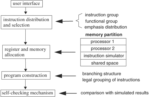
In this section we will look at the architecture of a generic pseudorandom test generator through the design of a pseudorandom processor code generator. A pseudorandom processor code generator creates programs run on a processor so that the programs test certain emphasized instructions and architectural features. The major components of a pseudorandom code generator are shown in Figure 5.7.
The user interface allows the user to specify the instructions and system features to be emphasized in generating random code. For instance, one may stress storing and loading instructions and test MMU functionality. Another example is to test cache coherency.
The user selectable parameter set usually consists of instruction groups, architectural function, selection probability distribution, degree of data dependency, and methods of result checking. Instructions are grouped according their functionality and nature. Typical groups are floating point instructions, arithmetic and logical operations, branching instructions, address instructions, memory instructions, exception and interrupt instructions, multiple-processor communication instructions, and data movement instructions.
Architectural function stresses individual functional units and interactions among functional units. Example architectural function groups are cache coherency, interrupt and exception handling, instruction prefetcher, instruction decoding, cache line-fill, Multiple-Processor (MP) snooping operation, multistrand operation, privileged memory access, atomic operations, Direct Memory Access (DMA) operation, pipeline stall and flush, and many others. When a feature is selected, the generator assembles the necessary instructions to create the scenario.
The selection probability distribution forces some instructions or functions that are more likely or less likely to be included in the generated programs. The code generator should have the capability of automatically generating default distributions and should be able to vary the distribution from run to run to explore fully the entire space. For example, a Gaussian distribution on architectural function groups selects the function groups according to a Gaussian distribution, with the highest emphasized group located within one sigma of the mean, the second highest emphasized group within two sigmas, and so on.
Data dependency is accentuated by restricting instructions to use only a specific subset of registers and memory locations. Address space restriction creates data dependency because an instruction can be executed only after all its operands are available. For example, an instruction attempting to store to a register must wait until the existing content of the register is no longer needed and can be safely overwritten. The same principle applies to memory addresses. Therefore, the smaller the size of the address space, the stronger the dependency among the instructions.
Randomly generated code is useful only if there are ways to check the results. Therefore, it is imperative that a code generator create self-checking routines for the random code. Self-checking routines require expected results for comparison. Result checking can be done at the end of each instruction or at the end of a program run. To produce the expected results, the generated instructions are simulated by the generator. This simulation can be done at the time the generated program is executed or at the time the program is generated. Expected results usually consist of register values and values at some memory locations. Then the expected results and comparison operations are inserted in the generated program. The advantage of simulating instructions concurrently with running the generated code is the added testing capacity, at the expense of a longer execution time.
In addition to the restriction on register and memory location use imposed by data dependency, registers and memory space are partitioned for different use. Some registers are reserved for storing address offsets, some as link registers for storing the base address on returning from a subroutine call, some as general-purpose registers, and some as data registers for store and load instructions. The memory space is partitioned so that each processor has address ranges for data and stack. All branching instructions should have target addresses within this assigned range. If instructions are simulated concurrently with code execution, the simulator will have a code and data memory segment to carry out the simulation. Finally, there is shared memory space among processors and the instruction simulator.
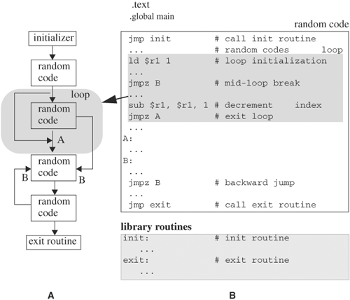
During this step, instructions are selected according to the user-specified distribution and to form a program to stress the selected system features. The instructions are assembled in a legal order. For branching instructions, target addresses are resolved after the instructions are put in order. For loop constructs, the loop index is initialized and the exit condition is added. After the main program is created, an initialization subroutine is inserted at the beginning and an exit subroutine is appended. The initialization routine saves the registers’ values and then fills the registers and data memory space with random numbers constrained by the user-set distribution. The exit subroutine ensures that all processes have finished or an error is recorded. Then it restores the registers’ values saved by the initialization routine. An example program structure and program layout are shown in Figure 5.8. In this example (Figure 5.8A) shows a template of the program flow. The flow contains a loop in a shaded area that has two exit points to label A and label B. Many different flows can be selected with this generator. Once the flow of the program is set, the code for the blocks is randomly selected according to the user-chosen distribution. Figure 5.8B shows a sample random code segment. The initializer and exit routines are library routines that are linked with the generated program. The loop is implemented with an index initializer and an index decrementer, and two jump instructions to exit the loop (see the upper shaded area of Figure 5.8B).
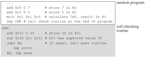
A randomly generated program runs on a processor and, at the end of the run, the result (values of registers and some memory locations) is compared with the expected result. The expected values are computed by the program generator. For instance, if a random program is a multiplication operation and the multiplicands are 7 and 5 respectively, the result will be in register R1. The generator computes the product and stores 35 as the expected value in a register, say R31. Then the generator appends a comparison routine to the random program that checks the value of R1 with that of R31. If they are equal, a passing message is issued; otherwise, a fail message is issued. Figure 5.9 shows a code segment of the self-checking mechanism.
Assertions are constructs, in the form of a group of statements, a task, or a function, that check for certain conditions on signals or variables in a design over a span of time. If the condition is violated, an error message is issued identifying the location of the occurrence. Assertions have been used in software and hardware design for quite some time, but only until recently have there been coordinated efforts to standardize assertions. An example of an assertion is that chip select, CS, is high whenever active low signal WR is low. If this requirement is not met, the assertion fails and an error message is issued. If it passes, there may not be a message issued. However, it is essential to keep track of the assertions that have passed, because silence could also mean that an assertion was not encountered. In Verilog, the assertion is
// assertion
'ifdef ASSERTION
if ( (WR == 1'b0 && CS == 1'b1) == 1'b0 )
   $display ("ERROR: !WE && CS failed. WR=%b,CS=%b",WR,CS);
'endif
Because assertions are not part of the design, they should be able to be conveniently excluded from the design. In this example, the assertion is enclosed within directive ifdef and can be stripped by not defining ASSERTION.
Assertions can be inserted throughout a design to detect any problems immediately. Without using assertions, one must rely on primary outputs to detect errors that often manifest the errors many cycles after their occurrence, hence making debugging difficult. Worse still are the situations when errors never propagate to a primary output. Therefore, a major advantage of using assertions is enhancing error observability and debugability. Furthermore, by standardizing assertions, they can be reused for new projects. In addition, assertions, now mainly used in simulation-based verification, can be used as specifications of design properties during formal method-based verification. For instance, the previous code example in a standard form may look like assert(!WR&&CS), which can be a simple runtime check on (!WR&&CS) during simulation verification, or it could be a property that (!WR&&CS) must be proved to hold in formal verification.
There are two approaches to defining assertions. We can start with specifications and conclude that certain behaviors or properties of the design must hold, which we call affirmative assertion, or we can start with design faults or some features or behaviors not specified, derive conditions that when met indicate that anomalies have occurred, and assert that these conditions must not be satisfied, which we call repudiative assertions. Both affirmative and repudiative assertions originate from and codify the items in a test plan. Test items state the functions or features to verify, and assertions translate these objectives into measurable signals and variables. Therefore, a comprehensive test plan should precede a robust assertion plan.
To illustrate deriving assertions from test items, consider a test item in category 1 (input guarding) of the state space approach for test plan creation. The item specifies which input patterns are illegal. Hence, an assertion can check for the specified input pattern. If an illegal pattern is encountered, a warning or error is issued. This application of assertions is especially informative when embedded in IPs or reusable designs for which the designers assumed a particular input configuration and have no control of the environment in which the design would reside. By embedding the input-guarding assertions, users can be warned of application environments unsuitable for the design. As another example, consider a category 5 (power-on test) test item that states that after power-on, all stacks are empty. To codify this condition, an assertion is activated by a power-on signal and, once activated, it compares all stack pointers with their respective top pointer. If they are unequal, an error is issued.
Like specifications, assertions exist in a hierarchy. There are assertions at the system level, unit level, and module level. As an example of a module-level assertion, consider a First-In-First-Out (FIFO) and a category 3 (operational anomaly) property. An assertion is that an error occurs if an empty FIFO is popped or if a full FIFO is pushed. During hierarchical verification, assertions can be classified into those monitoring internal operations of the building blocks and those ensuring correctness of the interactions among the building blocks. An example of the latter is the following: In a system consisting of a processor and external memory connected through a Peripheral Component Interconnect (PCI) bus, an assertion that a store command issued by a processor will cause the PCI bus to execute the corresponding transactions and after a number of cycles, memory has the data stored at the specified address.
Assertions have four major components: signal archive, triggering condition, assertion, and action. The first component is a signal archive that stores past values of signals and variables. The archive is just a memory or a shift register storing past values of signals and variables. The second component is a triggering expression that activates the assertion if the expression evaluates to true. This expression sets the conditions the assertion should be effected. An example of a trigger expression is if (init_done), which turns off all assertions during the power-on period in which unknown signal or variable values may falsely fire assertions and turns on assertions when initialization is done. The third component is an expression that checks a property or condition on signals and variables, and calls the fourth component if the check fails or passes. The fourth component is an action, called by the assertion, that prints a message if the assertion fails or may do nothing if it passes. Figure 5.10 depicts the four components of a sample assertion.
An expression contains variables or signals over a range of cycles. An expression is combinational only if it uses the current value of its variables or signals; otherwise, the expression is sequential. Denote the value of signal S, n cycles in the past, by S−n and m cycles in the future by S+m. Then the value at last cycle is S−1, the value at next cycle is S+1, and the current value is simply S. The following Boolean expression is combinational,
(A != 0 ) && ( A & (A−1))
whereas the following expression is sequential. It states that if signal A changes value from last to current cycle, then it should hold the value for the next cyle. -> is the implication operator.
(A-1 != A) -> (A == A+1)
An assertion is combinational if all of its expressions are combinational; otherwise, it is sequential. To code combinational assertions, only combinational logic is needed. To code sequential assertions, a finite state machine is required. If an expression has both past and future variables, the time interval from the most past and to the most future is the time window of the expression.
In the following section, we discuss common techniques of checking signal properties. First we discuss combinational assertions and then sequential assertions.
The simplest kind of assertion is to check whether a signal’s value is within an expected range. This is done by comparing the signal’s value with a minimum bound and a maximum bound. If the value lies outside the bound, an error has occurred. Sample code that checks whether signal S is out of bound [LOWER, UPPER] is
if ( 'LOWER > S || S > 'UPPER )
   $display ("signal S = %b is out of bound");
An assertion may not need to be active all the time. For instance, during the power-on period, S may not have been initialized and the assertion should be turned off. To activate the assertion only when S is ready, a triggering expression is added:
always @(posedge clock)
begin
if ( (ready_to_check == 1'b1) && ('LOWER > S || S > 'UPPER ))
   $display ("signal S = %b is out of bound");
end
Many assertions used in practice fall into this type of assertion, sometimes with a minor change. Table 5.3 lists some variants of signal range assertion.
Table 5.3. Variants of Signal Range Assertion
Assertion Name | Description | Code Variation |
|---|---|---|
Constant | Signal’s value remains constant | UPPER = LOWER; or, simply use event control to detect change (e.g., |
Overflow and underflow | Signal’s value does not overflow or underflow the limit of operation | No code modification is needed |
Maximum, minimum | Signal’s value does not exceed a lower or upper limit | No code modification is needed |
Checking whether signal A is equal to an unknown value cannot be done by simply comparing A with x, because A can have multiple bits. The assertion is to ensure that no bit of A has an unknown value. This assertion is needed in situations when data patterns are expected on A (for instance, data bus to memory during a write cycle). A brute-force check is to go through each bit of A and compare it with 1’bx. A more clever method is to use a reduction XOR operator, ^. A reduction XOR performs XOR on all the bits of A, one by one. By definition of XOR, if at any time an operand has an unknown value X, the result will be X regardless of other operand values. Thus, the reduction XOR will produce an X result if and only if at least 1 bit of A is X. The Verilog code to check for an unknown value on signal A is
if ( ^A == 1'bx) $display ("ERROR: unknown value in signal A");
A signal is of even parity if the number of 1s is even, such as ^A gives 0. Similarly, A is odd parity if ^A is 1. To check a signal’s parity, reduction XOR can be used, which XORs all bits of the signal together. If the result is 1, the parity is odd; otherwise, it is even. The code for checking even and odd parity is as follows:
if ( ^A == 1'b0) $display ("info: signal A is even parity");
if ( ^A == 1'b1) $display ("info: signal A is odd parity");
This type of assertion ensures that a set of signals is equal to expected values or differs from unwanted values. The expected values can be valid opcodes and the unwanted values can be unknown values. As an example, consider checking an instruction variable, instr, against a list of legal opcodes: BEQ, JMP, NOOP, SHIFT, and CLEAR. The comparison can be done by using either the comparison operator == or a case statement, as shown here. The macros (for example, BEQ and JMP) are defined to be the corresponding opcode binaries:
'define BEQ 1010
'define JMP 1100
'define NOOP 0000
'define SHIFT 0110
'define CLEAR 1000

if( (instr != 'BEQ)   &&
    (instr != 'JMP)   &&
    (instr != 'NOOP)  &&
    (instr != 'SHIFT) &&
    (instr != 'CLEAR))
$display ("ERROR: illegal instruction instr = %b", instr);
Or, embed a case statement within the body of an instruction execution unit:
case (instr):
   'BEQ: execute_beq();
   'JMP: execute_jmp();
   'NOOP: execute_noop();
   'SHIFT: execute_shift();
   'CLEAR: execute_clear();
   default:
   $display ("ERROR: illegal instruction instr = %b", instr);
endcase
Several signals can be concatenated and compared against a set of legal values. Grouping signals gives a more concise description and opens the opportunity for using don’t-cares in the expressions, as illustrated next. For example, we restrict single-bit signals reset, load, cs, hold, and flush to the values {10001, 11001, 00110, 01110}, which can be simplified using don’t-care notation to {1?001, 0?110}. To take advantage of don’t-cares, use the casez statement for comparison:
sigSet = {reset, load, cs, hold, flush}
casez (sigSet) :
   1?001: // do something
   0?110: // do other thing
   default:
      $display ("illegal control signals ...);
endcase
A signal is one-hot if exactly 1 bit of the signal is 1 at any time. To assert the one-hot property, instead of comparing the bits of the signal with 1, 1 bit at a time, the following simple code accomplishes the goal:
if ( |(B & (B - 'WIDTH'b1)) != 1'b0 )
   $display ("Bus B is not one hot, B = %b", B);
The macro WIDTH is the width of signal B. To see why this expression detects the one-hot property, try sample value B equals 8'b00010000.
                B : 8'b00010000
         B - 8'b1 : 8'b00001111     // subtract 1
   B & (B - 8'b1) : 8'b00000000     // bitwise AND
| (B & B - 8'b1 ) : 1'b0            // reduction OR
If B is not one-hot, say, B equals 8'01001000, then
              B : 8'b01001000
         B-8'b1 : 8'b01000111
   B & (B-8'b1) : 8'b01000000
| (B & B-8'b1 ) : 1'b1
Sometimes, a one-hot signal has a 0 value when it’s not active. A 0 value is not one-hot, but the previous algorithm does not distinguish 0 from one-hot. To eliminate 0 from being one-hot, a comparison with 0 is added to the previous one-hot-checking code, as follows:
if ((B != 'WIDTH'b0) &&
    ( | (B & (B - 'WIDTH'b1)) != 1'b0 ))
In addition, some bits of a one-hot signal can have unknown values when inactive. To accommodate this situation, a check for value X is added to the one-hot assertion, as follows:
if ((^B != 1'bx) &&
    (B != 'WIDTH'b0) &&
    (|(B & (B - 'WIDTH'b1)) != 1'b0 ))
OR
if ((^B != 1'bx) &&
    (|B != 1'b0) &&
    (|(B & (B - 'WIDTH'b1)) != 1'b0 ))
A one-cold signal, on the other hand, has exactly 1 bit equal to 0. To assert on one-cold, invert the signal bit by bit and use the previous one-hot assertion:
B = 'WIDTH{1'b1} ^ C;
where C is a one-cold signal. ’WIDTH{1’b1} creates a mask of 1s with a width of ’WIDTH (for example, 8{1’b1} is 8’b11111111).
Sequential assertions involve past and future values of variables. The key is to create a signal archive that saves the past values of the variables. A simple archiving mechanism is a shift register file for each variable such that at each clock transition, the current value of the signal is shifted in. The length is the register file equal to the history required for the assertion. The shift register file is clocked by the variable’s reference clock. To evaluate an assertion, the past values of the variables are retrieved from the shift register files. For example, consider writing an assertion to ensure that a Gray-coded signal changes exactly 1 bit at a time. The assertion first determines the bits that change by bitwise XORing the current value with that of the previous cycle (A = S-1 ^ S). If a bit changes, the corresponding bit position in A is 1. Then we determine how many bits have changed by checking whether A is one-hot. If A is one-hot or 0, the signal did not violate the Gray coding requirement. The code is as follows:
A = prev_S ^ S; // prev_S = S-1
if (~((A == 0) || | (A & (A-1) ) ) // one-hot assertion
   $display ("ERROR: Gray code violation");
where S-1 or prev_S can be obtained as follows:
initial
   curr_S = 1'bx;
   // assume S (curr_S) is one-bit; or use ('WIDTH-1) {1'bx}

always @(posedge clock)
begin
   prev_S = curr_S;
   curr_S = S;
end
In general, to save the previous N values of a signal S, a circular queue of length N + 1 is used, N slots for the N past values plus one slot for the current value. Figure 5.11A illustrates the movement of the queue over time. The queue rotates clockwise one slot every time the clock clicks, but the external labels (S, S-1, ..., S-N) remain stationary. At every clock tick, the current value of the signal is stored in the slot facing label S. Thus, after N clock ticks, the queue is fully filled, and now all N past values are available. A piece of Verilog code implementing the circular queue is as follows:
reg ['WIDTH-1:0] CQ [N:0]; // WIDTH is width of S
integer i; // index of the current cycle
integer j; // index of the jth past value

initial i = N;

always @(posedge clock)
begin
   i = i + 1 ;
   i = i % (N+1); // circular index
   CQ[i] = S; // present value
   // retrieving kth past value
   j = (i-k>=0) ? i-k : i-k+N+1 ; // calculate circular index
   prev_k_S = CQ[j];
end
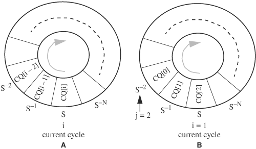
Figure 5.11. Circular queue for archiving past signal values. (A) A circular queue before a clock tick. (B) A circular queue rotates after a clock tick.
Signal S-k, 1 ≤ k ≤ N, is CQ[j], where j = i - k, if i - k is nonnegative; otherwise, j = i - k + N + 1.
Once past values of signals are computed, assertions over the history of signals can be written. An example assertion over signal history is as follows: If Req is 1, then Ack should turn 1 three cycles later, which causes Req to return to 0 seven cycles later. Whether this assertion fails will not be known until ten cycles after Req becomes 1. After Req has become 1, values of Ack and Req are archived for the next ten cycles. By then, passage of the assertion can be determined. Let prev_k_Req and prev_k_Ack denote the past kth value of Req and Ack respectively:
if (prev_10_Req == 1'b1)
   if ( !(prev_7_Ack == 1'b1 && Req == 1'b0) )
      $display ("ERROR: assertion failed");
If we use circular queues CQ_Ack and CQ_Req for Ack and Req respectively, and choose N to be ten, then the assertion takes the form
always @(posedge clock) begin
   i = i + 1;
   i = i % 11;
   j1 = (i−7>=0) ? i−7 : i + 4; // index for Ack
   j2 = (i−10>=0) ? i−10 : i + 1 ; // index for Req
   if (CQ_Req[j2] == 1'b1)
      if (!(CQ_Ack[j1] ==1'b1 && Req == 1'b0) )
         $display ("ERROR: assertion failed");
end
Note that this code should be activated after at least ten cycles have passed.
Once the history of signals is available, and together with combinational assertions, we can obtain assertions on many common signal properties. Table 5.4 lists some common assertions that can be implemented by applying combinational assertions to the signals’ history.
Table 5.4. Assertions on Signal Change Pattern
Assertion | Description | Coding Algorithm |
|---|---|---|
Gray code | At most, 1 bit changes. | S^S−1 is one-hot. |
Hamming code, H | Number of bit changes is H. | S^S−1 has H ls. |
Increment, decrement | A signal increments or decrements by a step size, N. | (S − S−1) or (S−1 − S) is N. |
Change delta | A signal’s change is with a range, R. | |(S − S−1)| is within range R. It is a signal range check. |
Transition sequence | A signal’s transition follows a certain value pattern. | {S, S−i, S−j, S−k,...,} has the pattern value. It is a signal membership check. |
Cause and effect | Signal | A−N -> B asserts. |
These assertions determine whether a signal does or does not change over a period of time or within a period specified by a pair of events. In the case when the time period is delimited by a number of cycles, a repeat statement can be used to perform the check. For instance, assume that a signal must remain unchanged for N cycles, checking is done by embedding S−1 == S in a repeat loop of N iterations. In the code, signal S is sampled at every positive transition of the clock, and thus it is assumed that signal S changes only at the clock’s transitions:
repeat (N)
   @(posedge clock)
      if (prev_S != S) $display ("ERROR...");
In the other case, when the interval is specified by a pair of events, signal S must be monitored for changes all the time, not just at some clock transitions. This situation is related to an asynchronous timing specification and it is discussed in “Unclocked Timing Assertions” on page 243.
The previous discussion assumes that the cycle numbers of the past values are specified, such as signal value seven cycles ago. On the other hand, if a range, instead of the exact cycle number, is specified (such as, S will rise some time between cycle 1 and cycle 10 after signal Ready is set), then the assertion can be implemented by embedding the check inside a loop with an iteration count equal to the range. The following code asserts that S will rise some time from cycle 1 to cycle 10 after signal Ready is set. When S rises, it immediately disables the block. If S does not rise after ten cycles, an error will be displayed:
always @(posedge clock)
begin: check // named block
   if ( Ready == 1'b1 ) begin
      repeat (10) @(posedge clock)
         if ( (prev_S != S) && (S == 1'b1) ) disable check;
          // assertion passes, exit
   end
   $display ("ERROR: assertion failed");
end // end of named block, check
Similar code can be written for assertions about an event that should not occur throughout an interval. If the event occurs within the interval, an error message is issued and the block is disabled. If not, it silently passes. For example, the following code asserts that address [31:0] remain steady for ten cycles after WR becomes one:
always @(posedge clock)
begin: check
   if (WR == 1'b1)
      repeat (10) @(posedge clock)
         if ( prev_Address != Address ) begin
            $display ("ERROR: Address changed");
            disable check;
         end
end // end of named block, check
Thus far, all timing constraints use a clock cycle as a reference. Hence, this way of constraining is not applicable for assertions that do not have explicit clocks. Situations with no reference clocks occur in high-level specifications that constrain the order of event occurrences without specific delays. For instance, signal R must toggle after signal S becomes high, with no requirement on how soon or how late R must toggle. Here we need to study two cases. The first case concerns an expression that should remain steady within an interval. The second case involves an expression that should attain a certain value within an interval. The interval is defined by two transitions—one signaling the beginning and the other signaling the end. An example of the first case is that the WR line must not change during a read or write cycle. An example of the second case is that signal Grant must attain a value and remain steady until signal Req is lowered. Unlike the situations with reference clocks, the expressions must be constantly monitored throughout the interval, as opposed to monitoring just at clock transitions.
To construct an assertion for the first case, the delimiting events and the expressions or signals are monitored using the event control operator @. The following example code ensures that S remains steady throughout the interval marked by events E1 and E2. The assertion is active only when guarding signal Start becomes 1. Two named blocks are created: one block waiting on E1 and the other, E2. If the assertion fails before E2 arrives, an error is displayed and the E2 block is disabled. If E2 arrives before any failure, the E1 block is disabled:
always @(posedge Start) // guarding statement
begin: check
   @ (E1);
   @ (S) $display ("ERROR: signal S changes");
      disable stop;
end

always @(posedge Start) // guarding statement
begin: stop
   @ (E2) disable check;
end
To prevent a hanging situation, when E2 never arrives, another block can be created to impose an upper time limit on the interval:
always @(E1)
begin: time_limit
   @(posedge clock) begin
      count = count + 1;
      if (count > LIMIT) begin
         $display ("ERROR: interval too long");
         disable check
         disable stop; // disable the ending block
      end
   end
end
When E2 arrives, block stop has to disable block time_limit because the stopping event has already arrived, and thus checking for its arrival time becomes irrelevant. A modified block stop is as follows:
always @(posedge Start) // guarding statement
begin: stop
   @ (E2) begin
      disable check;
      disable time_limit;
   end
end
For the second case that asserts an expression to attain a certain value during an interval, the expression is first monitored for changes. When a change occurs, the value of the expression is checked. The interval is instrumented with two named blocks: one block waiting on the first event and the second block waiting on the second event. We can illustrate this with the assertion that signal Grant cannot change until signal Req lowers, and this sequence of transitions must happen within an interval:
always @(posedge Start) // guarding statement
begin: check
   @ (E1); // beginning event
   @ (posedge Grant)
   if (Req != 0) $display ("ERROR: Grant changed at Req = 1");
   disable stop;
end

always @(posedge Start) // guarding statement
begin: stop
   @ (E2) $display ("ERROR: Grant never changed");
   disable check;
end
If signal Grant changes within the interval, the value of Req is checked. If it’s not 0, an error will be issued. In either case, block stop will be disabled when Grant arrives. Therefore, if block stop has not been disabled when event E2 arrives, it means that signal Grant never changed in the interval and an error will be issued.
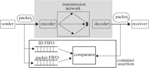
Assertions can also check the integrity of the data without knowing the exact data values. These assertions ensure that design entities remain intact after they have gone through processing. An example is that the content of a cache block remains the same from the time it is filled to the time it is first accessed. Another example is that a packet received is the same packet sent, even though the packet has undergone encoding, transmission, and decoding. This type of assertion contains local variables or containers that save the data before processing, and use the saved data to compare with the data after processing. Let’s illustrate container assertion with following packet transmission example.
In this example, packets are encoded, transmitted through a network, decoded, and received. We want to write a container assertion to check for data integrity of the packets—namely, the received packets were not corrupted during the process. We assume each packet is identified by an ID and packets arrive in the same order they are sent. When a packet is sent, signal SEND toggles. The container assertion has two FIFOs: one for the packet ID and the other for the packet data. When SEND toggles, the packet’s ID is pushed into id_FIFO, and the packet data are saved in packet_FIFO. The packet also carries its ID. On the receiving end, when a packet arrives, signal RECEIVE toggles, and the ID is extracted from the packet. At the same time, an ID is also retrieved from id_FIFO for comparison. If there is no match, an error is issued. If there is a match, the saved data are retrieved from packet_FIFO and are compared with those of the received packet. If there is a difference, an error has occurred. The transmission process and its interactions with the assertion are shown in Figure 5.12.
The following abridged code implements the container assertion:
always @(SENT) begin
   push_idFIFO(ID);
   push_packetFIFO( packet);
end

always @(RECEIVE) begin
   ID1 = get_FIFO();
   ID2 = get_ID_from_packet (packet);
   if (ID1 != ID2) $display ("ERROR: packet out of order");
   else begin
      org_packet = get_original_packet (packet_FIFO);
      ok = compare_packet (packet, org_packet);
      if (!ok) $display ("ERROR: packet corrupted");
   end
end
If we relax the requirement that the arrival order has to be the same as the sending order, id_FIFO would have to be replaced by another data structure that is more amicable to matching, such as a hash table. Then, when a packet arrives, its ID is extracted and is sent to the hash table for matching. If it is found, the packet content is then compared; otherwise, an error has occurred.
An alternative to writing assertions from the ground up is to use commercial built-in assertions. Most of these assertions are called as functions and they offer checks in a wide range of abstraction, from signal level to protocol level. Assertions can be categorized according to the functions they check. Some common categories are signal or variable property, temporal behavior, control and data checks, interface, and protocol.
Signal property may consist of checks for “one-hot-ness,” Hamming distance, parity, overflow, and change range. Temporal behavior may include checks for expected transitions or no transitions within a time interval, sequences of signal transitions at specified times, and order of signal changes without timing constraints. Control and data checks ensure proper operations for functional units such as FIFOs, stacks, memory, encoders, finite-state machines, and buses. Example checks include: no “enqueue” command is issued when the FIFO is full, data popped are identical to those pushed, memory address lines are steady when the read or write line is active, no unknown values are written to the memory, read locations have been initialized, state transitions are within the legal range, and, at most, one driver is active on a bus at any time. Interface checks ensure that interactions among functional units are correct. Some example checks include signal sequencing is correct during a DMA transaction, commands to the Universal Serial Bus (USB) port are legal, and data sent from the processor are received intact by main memory. Protocol checks are high-level assertions that ensure the specific protocols are followed at all times. Example checks include: PCI protocol is followed, bus arbitration is fair to all units, and critical shared resources are “mutexed” (in other words, only one client can access at a time).
These built-in assertions can be invoked as stylized comments, inline functions, or PLI system tasks:
always @(posedge clock)
   case (PS):
      NS = ...; // assertion check_state_transition(PS, NS,
                       clock,...), stylized comment assertion

grant= (idle ? ... ) ;
check_arbitor (grant, request, ...); // inline assertion

if( command == 'ENQUEUE) ...
$check_fifo(command, ...); // PLI system task assertion
Stylized comment assertions are recognized only by the assertion tool that processes the assertions and performs the checks during simulation. Because these assertions are comments, they are not part of the design. Inline assertions are implemented as modules, functions, tasks, or keywords specific to the vendor’s simulator. They should be enclosed within a pair of Verilog pragmas for easy removal from the design code, such as ’ifdef ASSERTION ... ’endif. PLI system task assertions perform the checks in C/C++ code. Like inline assertions, they should be embedded within a pair of ifdefs.
Although most assertions can be written using Verilog constructs, the assertion code can be lengthy and complicated, making maintenance and reuse difficult. In SystemVerilog language, built-in constructs are proposed to express succinctly the intent of commonly encountered verification assertions. These assertion constructs can serve as assertions for simulation-based verification as well as property specifications for formal method-based verification. Although at the time of this writing the exact syntax of SystemVerilog assertions has not been standardized, the concepts conveyed should persist into the future. Let’s discuss the key constructs of SystemVerilog assertions. For more details and updates about the syntax, please refer to IEEE 1364 SystemVerilog documents.
Two types of assertions exist in SystemVerilog: immediate assertions and concurrent assertions. Immediate assertions follow simulation event semantics for their execution and are executed like any procedural statement. Assertions of this nature are also called procedural assertions. They are just Verilog procedural statements preceded with the SystemVerilog keyword assert, which behaves like an if-then-else statement. If the assertion passes, a set of statements is executed; if it fails, another set of statements is executed. For example, to write to memory, we first ensure ![]() (chip select) is low and signal
(chip select) is low and signal WR is high. If the condition is not met, an error will be printed; otherwise, a confirmation message is printed. The checking part and the associated actions are succinctly encapsulated by the immediate assertion construct. The following is an immediate assertion inside an always block:
always @(posedge write_to_memory)
begin // a Verilog procedural block
   data = ...;
   address = ...;
   ...
   // here is an immediate assertion
   assert (WR == 1'b1 && CS == 1'b0)
      $display ("INFO: memory ready"); // pass clause
      else $display ("ERROR: cannot write"); // fail clause
...
end // end of always
Either or both of the pass and fail clauses may be omitted. Immediate assertions check on Verilog expressions only and do not describe temporal behavior. Immediate assertions are used during simulation-based verification.
Concurrent assertions, on the other hand, describe temporal behavior, and, analogous to Verilog’s module, they are declared as stand-alone properties and can be invoked anywhere, just as a module is defined and instantiated. Assertions of this nature are also called declarative assertions. Concurrent assertion is to Verilog module as immediate assertion is to procedural statement. Concurrent assertions use sequence constructs to describe temporal behavior. The syntax of a concurrent assertion is
assert property (property_definition_or_instance) action

action ::= [statement] | [statement] else statement
If the property holds, the first statement is executed; otherwise, the statement after else is executed. The keyword property distinguishes a concurrent assertion from an immediate assertion. An example of a concurrent assertion is
assert property (hit ##1 read_cancel) $display("ok"); \
   else $display ("ERROR: memory read did not get \
   cancelled in time");
which asserts on the property hit ##1 read_cancel that if there is a hit on cache, the read to main memory should be canceled during the next cycle. If the property fails, an error is issued.
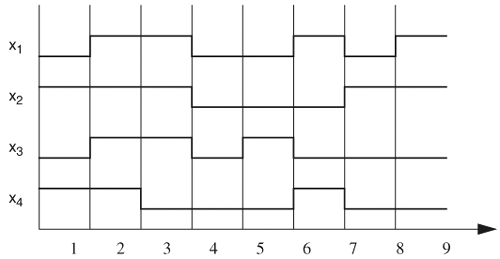
The main ingredient in modeling temporal behavior in property definition is sequence. A sequence is a list of Boolean expressions ordered in time—for example, sequence = {(Bi,Ti),i ∊ V}, where Bi is the Boolean expression at time Ti, and V is a set of integers denoting time (such as a cycle number). For example, sequence1 = {(x1 & ![]() + x3, 1), (x1 + x2), (x2 & x3, 3)}. For a sequence to be true, Bi must be true at Ti for all i in V. Therefore, for sequence1 to be true, (x1 &
+ x3, 1), (x1 + x2), (x2 & x3, 3)}. For a sequence to be true, Bi must be true at Ti for all i in V. Therefore, for sequence1 to be true, (x1 & ![]() + x3) must be true at time 1, (x1 + x2) must be true at time 2, and (x2 & x3) must be true at time 3. The property in this example is a sequence that translates into {(hit, N), (read_cancel,N + 1)}, where N is the current cycle. Sequences can model waveforms. A waveform with a 50% duty cycle and a period of 2 can be represented by sequence
+ x3) must be true at time 1, (x1 + x2) must be true at time 2, and (x2 & x3) must be true at time 3. The property in this example is a sequence that translates into {(hit, N), (read_cancel,N + 1)}, where N is the current cycle. Sequences can model waveforms. A waveform with a 50% duty cycle and a period of 2 can be represented by sequence
{(Si,i), Si = 1,i is even. Si = 0, i is odd. i ε Z}.
A sequence can represent several waveforms. If a waveform satisfies the sequence, then the sequence is said to have resulted in a match. For instance, sequence
{(Si,i), Si = a,i is even. Si = ā, i is odd. i ε Z}.
represents two waveforms, one of which is the previous waveform of the 50% duty cycle and period 2. The previous waveform has resulted a match in this sequence. The other waveform is the complement of the first waveform.
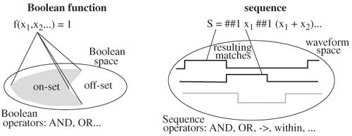
Sequence, therefore, is an extension of Boolean expression over time. Furthermore, although a Boolean expression describes the behavior of variables at an instance in time, a sequence describes the behavior of variables over time. A waveform is to a sequence as a vertex is to a Boolean function. For example, a Boolean function is true for the set of vertices in the on set of the function, and a sequence is true for the set of waveforms that result in matches for the sequence. Figure 5.13 contrasts Boolean domain with temporal (sequence) domain. Let’s divide our discussion on SystemVerilog assertions into two parts: the first part on sequence constructors and the second part on sequence connectives or operators.
The key to construct a sequence is to specify time. The first constructor is cycle delay specifier ##. ## N means N cycles of delay, and N can be any nonnegative integer. As an example, x1 ##3 x2 is equivalent to (x1, t1), (x2, t1 + 3). In other words, x2 is delayed by three cycles relative to the previous time. The argument of ## can be a range (##[n,m]), which means the delay is any number between n and m. For example, x1##[1,3] x2 is equivalent to the following:
     x1 ##1 x2
     or
     x1 ##2 x2
     or
     x1 ##3 x2
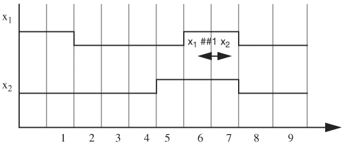
Therefore, for x1##[1,3]x2 to be true, at least one of the previous sequences must be true. Consider the waveforms in Figure 5.14. x1 ##1 x2 is satisfied at time 7 if it starts at time 6, because at time 6, x1 is true and one cycle later x2 becomes true. However, x1 ##2 x2 and x1 ##3 x2 are not satisfied with the waveforms. Therefore, sequence x1 ##[1,3] x2 is satisfied by the waveforms. To specify an unbound upper limit, $ denotes infinity (for example, ##[1,$] means any number of cycles greater than or equal to one).
As an example of constructing a sequence, consider the order of events that signal req is high, followed by ack going high three cycles later, and ending with req going low seven cycles later. The sequence is req ## 3 ack ## 7 !req. This sequence is true if and only if the previously described pattern occurs.
Just like a module, a sequence can be defined, with or without arguments, and can be instantiated elsewhere. For example, to define sequence mySeq, enclose the sequence within keywords sequence and endsequence:
     sequence mySeq ;
   ##1 x1 (x2) [*2,8] ##3 x1
     endsequence
To instantiate, just call mySeq,
##3 y mySeq #1 x
which is equivalent to
##3 y ##1 x1 (x2) [*2,8] ##3 x1 #1 x
To define a sequence with parameters, enclose the parameters inside a pair of parentheses. The following is an example of defining sequence seqParam with parameters a and b:
     sequence seqParam (a,b);
   ##1 a x1 ##3 (x1 == b)
endsequence
To instantiate the sequence, just call it by name and substitute values for the parameters. For example, the following instantiation
seqParam (y,z)
is equivalent to
##1 y x1 ##3 (x1 == z)
Larger sequences can be formed from sequences using connective operators, so that complex assertions can be built from simple ones. To duplicate a sequence over time, use the repeat operator [*N], which duplicates the preceding expression N times with one cycle delay inserted between duplicates. For example, (x1+x2) [*3] is equivalent to the following:
(x1 + x2) ##1 (x1 + x2) ##1 (x1 + x2) // duplicate 3 times
Note the one cycle delay was inserted between the duplicates. The argument of the repeat operator, N, can be a range (for example, [*n,m]) in which case it repeats for a number of times j, where n≤j≤m. For example, (x1+x2) [*1,3] is equivalent to the following:
     (x1 + x2)
     or
     (x1 + x2) ##1 (x1 + x2) // duplicate 2 times
     or
     (x1 + x2) ##1 (x1 + x2) ##1 (x1 + x2) // duplicate 3 times
Instead of separating duplicates by exactly one clock cycle, as in repeat operator [*n,m], two variants of the repeat operation allow arbitrary intervals between duplicates. To create patterns with arbitrary intervals between duplicates, use nonconsecutive repeat operators [*->n,m] or [*=n,m]. Nonconsecutive repeat operators allow other patterns to be inserted between duplicates. For example, x1##1x2 [*->1,3] ##1x3 is equivalent to
x1 ##1 (y ##1 x2) [*1,3] ##1 x3
where y is any sequence, including an empty sequence, that does not have x2 as a subsequence. Therefore, x1 ##1 (x4 ##1 x2) (x5 ##1 x2) ##1 x3 is an instance described by the previous construct. Formally, x1 ##1 x2 [*->1,3] ##1 x3 is equivalent to
x1 ##1 (!x2 [*0,$] ##1 x2) [*1,3] ##1 x3
Repeat operator [*=n,m] is a slight variation of [*->n,m] in that a ##1 is appended to the end of the result from the operator. That is, x1 ##1 x2[*=n,m] ##1 x3 is equivalent to
x1 ##1 (!x2 [*0,$] ##1 x2) [*n,m] ##1 !x2 [*0,$] ##1 x3
Sequence connectives build new sequences from existing ones. To build new sequences, some connectives place constraints on the operand sequences, such as start times and lengths, to make the resulting sequences meaningful. The idea behind sequence connectives is twofold. First, it makes creating complex sequences easy; second, it extends operations on variables to sequences so that temporal reasoning can be carried out in a manner similar to Boolean reasoning.
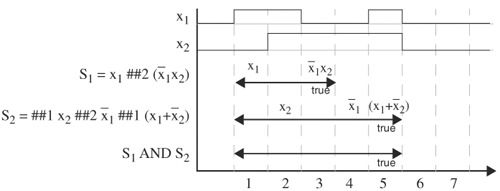
Sequences can be logically ANDed if the operand sequences start at the same time. Operation (sequence1 AND sequence2) is true at time t if and only if both sequences are true at time t, or one sequence is true at time t and the other has already become true at time t. Let’s use Figure 5.15 to determine whether S1 AND S2 is true on the given signal waveforms of x1 and x2, where S1 = x1 ##2 ![]() and S2 = ##1 x2 ##2
and S2 = ##1 x2 ##2 ![]() ##1 (x1 +
##1 (x1 + ![]() ). The horizontal double–arrowhead lines denote the time interval a sequence is evaluating, from the start time to the end time. Assume the current time is cycle 1. Sequence
). The horizontal double–arrowhead lines denote the time interval a sequence is evaluating, from the start time to the end time. Assume the current time is cycle 1. Sequence S1 starts at time 1 and ends at time 3. In cycle 1, the expression is x1, and in cycle 3, the expression is ![]() . From the waveforms, we see x1 is
. From the waveforms, we see x1 is 1 at cycle 1, and at cycle 3, x1 is 0 and x2 is 1. Therefore, S1 becomes true at cycle 3. The same goes for sequence S2, which becomes true at cycle 5. Hence, S1 AND S2 is true at cycle 5.
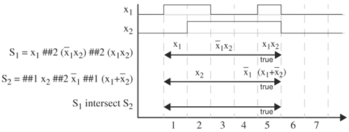
For intersection operation, sequence1 intersect sequence2 is true at time t if and only if both sequences are true at time t. This operator requires that both operand sequences start and end at the same time. Therefore, we cannot perform intersection on the sequences in Figure 5.15, because S1 and S2 do not end at the same time. If we change S1 to S1 = x1 ##2 ![]() ##2 (x1x2), then
##2 (x1x2), then S1 intersect S2 becomes true at cycle 5, because both sequences become true at cycle 5, as shown in Figure 5.16. If either or both sequences have multiple matches, only the pairs with the same start time and end time are considered.
sequence1 OR sequence2 is true at time t if and only if at least one sequence is true at time t. Both operand sequences start at the same time. For the sequences in Figure 5.15, S1 OR S2 is true at cycles 3, 4, and 5, because S1 is true at these times.
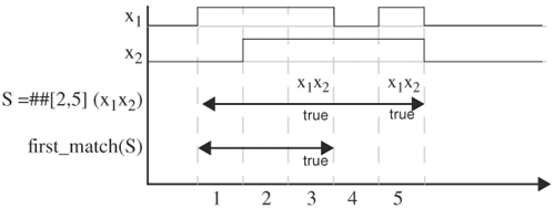
Operator first_match takes in a sequence and returns true when the sequence first becomes true. If the sequence expands to multiple sequences, such as ##[2,5](x1x2) expanding to four sequences, then first_match returns true when any of the expanded sequences first becomes true. The end time of first_match is the time it turns true. Figure 5.17 shows the operation of first_match. ##[2,5] (x1x2) expands to ##2 (x1x2) or ##3 (x1x2) or ##4 (x1x2) or ##5 (x1x2). Of these, ##2 (x1x2) and ##4 (x1x2) are true for the given waveforms. Operator first_match detects the first time the sequence becomes true (at cycle 3, ##2 (x1x2)). Thus, it returns true and ends at cycle 3.
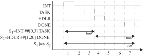
This operation is the same as the Boolean implication operator, A → B, which is Ā + A · B, except that it applies to sequences (for example, sequence1| → sequence2). If sequence1 is true at time t, then sequence2 starts at time t and its valuation determines that of the implication. If sequence1 is false, then the implication is true. A variation is sequence1|⇒ sequence2 for which sequence2 starts one cycle after sequence1 becomes true. An example use of sequence implications is when an interrupt signal arrives, the processor will wait up to three cycles. If all in-flight tasks are finished by then, the control is transferred to an interrupt handler in the next cycle. Once control is in the interrupt handler, it should finish within 20 cycles. Let INT, TASK, HDLR, and DONE denote the interrupt signal, in-flight task done signal, signal to start the interrupt handler, and handler finish signal respectively. This behavior can be described as (INT ## [0,3] TASK) |=> HDLR ## [1,20] DONE. This assertion is true at cycle 7 for the waveforms shown in Figure 5.18.
This operator, E throughout S, where E is an expression and S is a sequence, imposes expression E on sequence S. Recall that a sequence is {(Bi,Ti),i ε V}. Then E throughout S is {(E . Bi,Ti),i ε V}. An example is (x1 + x2) throughout (##1 x3 ##2 x4), which is equivalent to (##1 (x1 + x2)x3 ##2 (x1 + x2)x4). An applicable situation is that S is an assertion packaged with an IP module and the expression E is a condition describing the environment in which the IP is instantiated (for example, the peripheral signals to the IP must be within the correct ranges required by the IP). For the IP instance to work properly, the environment expression E must be true throughout the interval that the IP assertion holds. In other words, E is a predicate guarding the application of S.
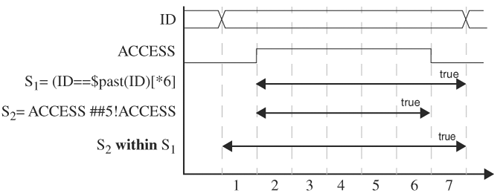
This operator, sequence1 within sequence2, tests whether sequence1 lies within sequence2 and whether both sequences succeed. This operation requires that sequence1 start and end after sequence2 starts and before sequence2 ends. The operation becomes true if sequence1 has become true and is true when sequence2 is true. S1 within S2 is equivalent to
(1 ##1) [*0,$] S1 (##1 1) [*0,$] intersect S2
An applicable scenario is that throughout an exclusive critical-section access, the ID of the accessing process should not change. Let S1 = (ID == $past (ID)) [*6], S2 = (ACCESS ##5 !ACCESS), where $past is a system function that returns the previous cycle value of the operand and thus (ID == $past (ID)) is true if ID has not changed since the last cycle. Sequence S1 asserts that the ID remain the same for six cycles, whereas sequence S2 asserts that access be done within five cycles. If variable ID does not change while the critical section is being accessed, (S2 within S1) is true. Figure 5.19 shows signal waveforms satisfying (S2 within S1).
A sequence can have local variables to hold data that are to be used in the future. An application checks whether the data that popped out of a stack are the same as the data pushed. The assertion uses a local variable to save the data when it is pushed into the stack. When the data are popped out, they are compared with the saved version. The following assertion does this check, saving data when push is high and comparing the popped data seven cycles later when it is popped. The container operator is the comma that separates push and the assignment in the antecedent:
int orig;
(push, orig = data |-> ##7 data = orig)
This operator, sequence.ended, returns true at the time when the sequence becomes true—that is, the time the sequence ends. An example application is to assert that signal grant lowers two cycles after sequence transaction finishes:
( transaction.ended ##2 !grant )
Built-in system functions in SystemVerilog simplify code writing. Some system functions are $onehot, $onehot0, $inset, $insetz, $isunknown, $past, and $countones. A system function takes in expressions as arguments, such as $onehot (bus) and returns the advertised value. The following list explains some common system functions.
$onehot (expression)returns true if only 1 bit ofexpressionis1.$onehot0 ()returns true if at most 1 bit ofexpressionis1.$inset (e1, e2, ...)returns true ife1is equal to one of the subsequent expressions. For example,$inset (cmd, ’WR, ’RD, ’CLR)is true whencmdis either’WR, or’RD, or’CLR. This function replaces the longer and more complex case statement.$insetzis similar to$insetexcept it treatszand?as don’t-cares, as incasez.$isunknown (expression)returns true if any bit ofexpressionis ofxvalue.$past (expression, i)returns the value ofexpression icycles prior to the current cycle. Ifiis omitted, it is defaulted to1. $past (e,i)is equivalent to e−i. With this function, asserting Gray code is simply$onehot (S ^ $past (S)).$countones (expression)returns the number of1s inexpression. An application is checking the parity of a signal.
So far, the number of clock cycles has referred to an inferred clock, which is the clock of the domain in which the assertion is embedded. SystemVerilog provides a way to write assertions driven by multiple clocks and references the cycle delays to their respective clocks. For instance, consider the sequence
@(posedge clk1) x1 ## (posedge clk2) x2
In this sequence, at every posedge of clk1, x1 is checked. If x1 is true, then on the next posedge of clk2, x2 is checked. Thus, ## serves as a synchronizer between the two clocks. If clk1 and clk2 are identical, the previous sequence reduces to
@(posedge clk1) x1 ##1 x2
Sequences can be defined and instantiated, making sequences reusable. The following code defines a sequence, called testSequence, to be ##1 A ##2 B ##3 (x == y):
sequence testSequence (x,y);
   ##1 A ##2 B ##3 (x == y)
endsequence
To instantiate testSequence, just invoke it by name, as shown here in another sequence definition:
sequence callSequence;
   @(posedge clock) testSequence (p,q)
endsequence
This sequence, callSequence, is equivalent to
@(posedge clock) ##1 A ##2 B ##3 (p == q)
The purpose of defining sequences is to facilitate assertion construction on temporal behavior. Expressions and sequences form properties that are asserted by assertions. SystemVerilog provides a way to define properties and instantiate them in different assertions. To define a property:
property SteadyID (x)
   @(posedge clock) (x == $past (x)) [*6]
endproperty
To assert property SteadyID:
assert property SteadyID (procID)
Because it is impossible to verify exhaustively all possible inputs and states of a design, the confidence level regarding the quality of the design must be quantified to control the verification effort. The fundamental question is: How do I know if I have verified or simulated enough? Verification coverage is a measure of confidence and it is expressed as a percentage of items verified out of all possible items. An “item” can have various forms: a line of code in an implementation, a functionality in a specification, or application scenarios of the design. Different definitions of item give rise to different coverage measures. As you may have anticipated, even defining item can be challenging, such as defining an item to be a functionality. Furthermore, it is even more challenging to determine all possible items, such as all functionalities in a design. In this section we will look at three coverage measures: code coverage, parameter coverage, and functional coverage. In our discussion we will assume that the underlying verification mechanism is simulation, because it is applicable to all three measures and because it lends itself to a clear explanation.
Code coverage provides insight into how thoroughly the code of a design is exercised by a suite of simulations (for example, the percentage of RTL code of a FIFO stimulated by a simulation suite). Parameter coverage (also referred to by some as functional coverage) reveals the extent that dimensions and parameters in functional units of a design are stressed (for example, the range of depth that a FIFO encounters during a simulation). Finally, functional coverage accounts for the amount of operational features or functions in a design that are exercised (for example, operations and conditions of a FIFO simulated: push and pop operation, full and empty condition). Note that code coverage is based on a given implementation and it computes how well the implementation is stimulated, whereas functional coverage is based on specifications only, and it computes the amount of features and functions that are verified. Parameter coverage can depend on implementation, specification, or both. Therefore, sometimes code and parameter coverage are referred to as implementation coverage, and functional coverage is referred to as specification coverage. Coverage measures based on implementation are only as good as the implementation, but are more concrete and hence easier to compute, whereas those based on specification are more objective and direct to what the design intended, but are more difficult to compute.
Each of the three coverage metrics has its shortcomings, but together they complement each other. Because code coverage assumes an implementation, it only measures the quality of a test suite in stimulating the implementation and does not necessarily prove the implementation’s correctness with respect to its specifications. As an extreme example, consider a 64-bit adder that is mistakenly implemented as a 60-bit adder. It is possible that every line of the 60-bit adder has been stimulated, giving 100% code coverage, but the implementation is wrong. This problem would be detected if parameter coverage is used. To detect it, parameter coverage has to include the size range of operands. Even with parameter coverage, problems with the carry-in bit may not be detected (for example, the carry-in bit does not propagate correctly). Functional coverage includes all specified functions (for example, in this case, addition of numbers, carry-in, and overflow operations). In this case, functional coverage analysis will detect the carry-in error. By defining operand size to be parameters, better verification coverage is achieved by supplementing functional coverage with parameter coverage which explores different sizes of operands.
Because it is easy to leave out parameter and functional items, code coverage can provide hints on missing functionality. Therefore, in practice, a combination of code, parameter, and functional coverage is used.
With regard to ease of use, the code coverage metric ranks first, followed by parameter then functional coverage. Code coverage is easiest because it involves accounting for code exercised. The difficulty of using parameter coverage stems from finding most, if not all, parameters in a design and determining their ranges. Once the parameters are found, an apparatus needs to be set up to track them. Functional coverage is the most difficult to construct and use, because all functions and features have to be derived from the specifications, and there is no known method of systematically enumerating all of them. Often, enumerating all functionality is not possible because specifications can be ambiguous or incomplete.
Coverage metrics are used to measure the quality of a design and can also be used to direct test generation to increase coverage. It should be noted that coverage numbers do not necessarily project a linear correlation with verification effort. It is conceivable that the last 10% of coverage takes more than 90% of the overall verification effort.
Code coverage depicts how code entities are stimulated by simulations. These code entities are statement, block, path, expression, state, transition, sequence, and toggle. Each entity has its own percentage of coverage; for example, code coverage may consist of 99% statement coverage, 87% path coverage, 90% expression coverage, and 95% state coverage.
Statement coverage collects statistics about statements that are executed in a simulation. For example, consider the code in Figure 5.20. Excluding the begin, end, and else lines, there are ten statements. If a simulation run is such that a > x at line 5 and x == y at line 12 are true, then all statements except those on lines 10, 11, 14, and 15 are executed in this run, as indicated by the arrows in Figure 5.20. Again excluding the begin, end, and else lines, eight lines are executed, giving 80% statement coverage.
Note that in Figure 5.20, once line 3 is reached, line 4 will be executed; that is, coverage of some statements automatically implies coverage of other statements. Therefore, the statements can be grouped into blocks such that a statement in a block is executed if and only if all other statements are executed. The dividing lines for blocks are flow control statements such as if–then–else, case, wait, @, #, and loop statements. The code in Figure 5.20 can be grouped as shown in Figure 5.21. During the simulation run, four of six blocks are executed, giving 66.67% block coverage. Because of the similar nature of statement coverage and block coverage, and the fact that blocks better reflect the code structure, block coverage is often used in lieu of statement coverage. Near 100% statement and block coverage are easy to achieve and should be the goal for all designs. There are types of code that prevent 100% statement or block coverage. The first type is dead code, which cannot be reached at all and is a design error. The other type of statement is executed only under particular environment settings or should not be executed under correct operation of the design. Examples of this type are gate-level model statements that are not activated in a behavioral simulation, or error detection statements or assertions that do not fire if there are no errors. Thus, these types of statements should be excluded from statement and block coverage computation.
Coverage tools should have a pragma to delimit statements that are to be excluded. For example, when a coverage tool encounters the pragmas coverage_tool off and coverage_tool on, it skips the statements between them and excludes the statements from coverage calculation. The exact pragma name and syntax depend on specific coverage tools:
// coverage_tool off
if( state == 'BAD )
   $display ("ERROR: reach bad state");
// coverage_tool on
Conditional statements create different paths of execution. Each conditional statement is a forking point. Path coverage metrics measure the percentage of paths exercised. For the code in Figure 5.20, a graph of paths of statement execution is shown in Figure 5.22. There are four possible paths (in other words, four combinations of if-else branches). Two paths are shown in Figure 5.22. Path P1 is where both if statements are true, whereas path P2 is where both if statements are false. For the simulation run under discussion, P1 is executed, giving 25% path coverage. The number of paths grows exponentially with the number of conditional statements. Therefore, it is difficult to achieve 100% path coverage in practice.
How a statement is executed can be further analyzed. For example, when the statement containing several variables or expressions is executed, a detailed analysis is: which of the variables or expressions did get exercised. For example, that the expression (x1x2 + x3x4) evaluates to 1 can be broken down into whether x1x2 or x3x4 or both evaluate to 1. Such detailed information, revealing the parts of the expression executed, can be used to guide test generation to exercise as many parts of the expression as possible.
To compute expression coverage, operators in an expression are layered. For instance, E = (x1x2 + x3x4) is considered to have two layers:
layer 1: E = y1 + y2
layer 2: y1 = x1x2, y2 = x3x4
The second layer consists of two subexpressions: y1 and y2. Each expression or subexpression is a simple operator (such as AND or OR) and its expression coverage can be calculated from the minimum input tables shown in Tables 5.5 through 5.7. A minimum input determining an expression is the fewest number of input variables that must be assigned a value in order for the expression to have a Boolean value. For simple operators, all minimum inputs determining the value of the expression can be tabulated. The number of entries in the table consists of all cases for the expression to be exercised completely. Expression coverage is the ratio of the cases exercised to the total number of cases.
As examples, Tables 5.5 through 5.7 show the minimum inputs for f = x1 & x2, f = ( y ? x1 : x2), and f = (x > y).
This table indicates three cases for the AND function. For AND to evaluate to 0, only one input needs to be assigned 0. Because there are two inputs, two minimum inputs exist for the AND expression to be 0. For AND to evaluate to 1, both inputs must be 1. Therefore, there are a total of three minimum input entries. A line in the table represents a don’t-care for the variable. If, during a simulation run, x1 and x2 take on values x1 = 1 and x2 = 0 at one time and x1 = 1 and x2 = 1 at another time, then two cases are exercised, giving two-thirds or 66.67% expression coverage for this operator.
For the quest operator y ? x1 : x2, if y evaluates to true, the expression’s value is then determined by that of x1. If y evaluates to false, x2 then determines the expression’s value. There are four cases, as shown in Table 5.6.
For the comparison operator, there are two cases: true or false.
For composite operators, expression coverage can be computed for either the top layer of the operator or for all layers. Deciding on the top or all layers is a matter of how precisely one wants to test an expression. As an example, consider f = ((x > y) || (a & b)). Input (x, y, a, b) takes on values (3, 4, 1, 1) and (2, 5, 1, 0) during a simulation. The top layer operator is OR (||). In this simulation, the operands of OR evaluate to (x > y) = false, (a & b) = 1, and (x > y) = false, (a & b) = 0, for (3, 4, 1, 1) and (2, 5, 1, 0) respectively.
Because the OR operator has three cases, this simulation has a top-layer expression coverage of two-thirds, or 66.67%. For the next layer, (x > y) evaluates to false, giving 50% expression coverage; (a & b) has two-thirds, or 66.67%, coverage.
State coverage calculates the number of states visited over the total number of states in a finite-state machine. The states are extracted from RTL code, and visited states are marked in simulation. Consider the following three-state finite-state machine (depicted by the state diagram shown in Figure 5.23), where state S1 is the initial state and S4 is not defined in the RTL code.
initial present_state = 'S1;
always @(posedge clock)
   case ({present_state, in})
      {'S1,a} : next_state = 'S3;
      {'S2,a} : next_state = 'S1;
      {'S3,a} : next_state = 'S2;
      {'S1,b} : next_state = 'S2;
      {'S3,b} : next_state = 'S3;
   endcase
If a simulation causes input in to be b, a, b, a, b, a, ..., then the state machine will only transit between S1 and S2, giving two-thirds, or 66.67%, state coverage. Because at least 2 bits are required to encode the three states, S4 is an implicit state and the state machine may end up at S4 for some error combinations on state bits. A more reliable design should consider how to handle S4. Therefore, for state coverage purposes, S4 should be counted and the previous input sequence would give only 50% state coverage. Because S4 can never be reached under normal operation, state coverage can be, at best, 75%. This should alert the designer that some states cannot be reached.
Transition or arc coverage records the percentage of transitions traversed, and, in some cases, the frequency they are traversed. For the state machine in Figure 5.23 and the input sequence b, a, b, a, ...,, only two of five transitions are traversed, giving 40% transition coverage. Note that the transition from S2 under input b is not defined. Including this undefined transition in the coverage calculation lowers the coverage to 33.33% and alerts us to potential problems. Therefore, the total number of transitions can be the actual number of transitions in the design or all possible transitions, which is equal to the number of states multiplied by the number of all possible inputs.
Sequence coverage calculates the percentage of user-defined state sequences that are traversed. A state sequence is a sequence of states that a finite-state machine traverses under an input sequence. For example, under input sequence a, b, a, a, a, b, b, the previous state machine traverses state sequence S1, S3, S3, S2, S1, S3, S3, S3. A user may specify that certain state sequences be traversed in a simulation run or not be traversed (in other words, illegal sequences). These state sequences could represent crucial functions or corner cases of the design. Sequence coverage provides information about which legal sequences are traversed and which illegal sequences are encountered.
Toggle coverage measures whether and how many times nets, nodes, signals, variables, ports, and buses toggle. Toggle coverage could be as simple as the ratio of nodes toggled to the total number of nodes. For buses, bits are measured individually. For instance, a change from 0000 to 1101 for a 4-bit bus gives three-fourths, or 75%, toggle coverage, instead of 100%, as if the entire bus were considered as a whole.
To compute code coverage, the RTL code must first be instrumented to have a mechanism installed to detect statement execution and to collect coverage data. There are two parts in instrumenting RTL code. The first part adds user-defined PLI tasks to the RTL code so that whenever a statement is executed, a PLI task is called to record the activity. Using the example in Figure 5.20, the code can be instrumented as shown in Figure 5.24. The user PLI task $C1 (), ... , $C5 () is added to the RTL code. When the statements in block 1 are executed, $C1 is called. If $C2 and $C4 are called at the same simulation time, then path P1 of Figure 5.22 is traversed. The C/C++ code of PLI tasks $C1, $C2, and so on, record the simulation times when they are called and write out the results to a file for postprocessing. A fragment of code is shown here:
void C1 ()
{
   ...
   time = $tf_gettime(); // get simulation time
   C1_call_frequency[time].frequency++;
   // C1_call_frequency is a look-up table taking in
   // simulation time T and returns the number of times C1 is
   // called at time T.
...
}
At the end of the simulation, table C1_call_frequency is dumped out to a file. The file’s contents may look like
routine:    time called:    frequency:
C1          1002             1
C1          1201             2
...
C2          1002             2
C2          1201             1
...
C3          1002             1
C3          2001             1
...
The second part of instrumenting creates a map that correlates the dumped output file to the filenames and line numbers of the RTL code. In Verilog, there are no means to get the filename and line number at which a user-defined PLI task is invoked; thus, a map is created to accomplish this goal. During the first part of instrumentation, when the PLI tasks are inserted, the filename and the line number of the insertion point are recorded in the map. Thus, a map contains data similar to
routine:    file name:    line number:
C1           cpu.v          3
C2           cpu.v          7
...
With this map, the calling frequencies of statements can be computed, from which block, path, state, transition, and other coverage metrics are derived. To evaluate expression coverage, the expression is passed to a PLI task and it is evaluated in C, through which the expression’s coverage is computed. For example, the expression on line 9, y = (b & a) is replaced by PLI task $C_exp (y, b, a), which takes on the values of variables a and b, computes the expression coverage, and returns the value of y. A postprocessor combines the dumped output and the map to create a coverage report.
After RTL code is instrumented, the instrumented code, instead of the original code, is simulated. Because PLI calls are involved in measuring code coverage, simulation performance is significantly decreased. It is not uncommon to see a 100% decrease in simulation speed once coverage measurement is turned on. Let’s look at several techniques to mitigate this problem.
For the code that the user does not want to measure coverage, or code that has been measured already, or error detection code that normal operations should not invoke, turn off the code with a pragma. Although the syntax of the pragma varies from tool to tool, a general form is shown here. The pragma is in the form of a stylized comment and it has no effect on other tools. Some coverage tools automatically ignore code marked by pragmas of synthesis tools, such as synthesize_off.
// coverage_tool off
// the following code is to be ignored
always @(posedge clock)
   begin
      ...
   end
// coverage_tool on
Ordering tests according to the parts of the circuit they cover improves performance. Coverage areas by each test can be represented using a Vann diagram. Tests with coverage that is subsumed by other tests should be eliminated. One way of ordering tests is to start with the test having the largest coverage area, followed by the test that has the most incremental change to coverage. When running a set of tests, the covered portions of circuit can be turned off progressively using pragmas so that a new test only measures the code that has not been covered by previous tests. When the code of a design is changed incrementally, we would identify the part of the design that is affected and update the coverage only for that part of the design.
A well-designed coverage tool should exhibit progressive performance improvements over a simulation run. During a simulation run, once a statement is covered, it does not need to be measured later in the simulation. For example, the PLI calls responsible for the statement can be disabled. Therefore, as coverage gradually reaches a plateau, simulation performance should gradually improve. At the coverage plateau, simulation speed should approach that without coverage measurement.
Finally, performance can be improved by simulating several tests in parallel and by combining the results. This technique is particularly useful in profiling tests on their coverage scope and using the profiling data to trim redundant tests and order tests.
A major shortcoming of code coverage is that it only shows whether code is exercised and provides only an indirect indication of correctness and completeness of the operation of the implementation. As discussed earlier, it is possible to have 100% code coverage on a completely wrong implementation. To gain further insight into operational correctness, parameter coverage is introduced to measure functional units. To motivate the need for parameter coverage, consider verifying a stack. Testing the pushing and popping of an item to a stack is only a point in the operational space of the stack, because the stack has a depth greater than one. A more robust verification will also test the stack at various depths, and when it is empty and full. Generalizing this rationale, we first enumerate all parameters in a functional unit and then we measure the extensiveness that the parameters are stressed. This measure is parameter coverage. In a sense, a high parameter coverage indicates that a particular test of an operation or function is expanded to various possible values of its parameters. In the example of a stack, a parameter is stack depth, and the parameter coverage records the depths encountered throughout a simulation. Hence, a good simulation effort should cover all depths, including empty and full, of the stack.
As another example, consider a 32-bit adder. A parameter is the width of the operands. A test with high parameter coverage operates the adder with operands of different widths. The parameter of operand width does not necessarily increment by one. If the 32-bit adder is constructed from 4-bit adders, then the parameter increments by four, meaning that the 32-bit adder can be verified by verifying the building block, 4-bit adder, and treating each unit of 4-bit adder in the 32-bit adder as a black box, and verifying the interconnection of the black boxes. This brings out the notion of equivalent tests. In this example, the tests verifying only the building blocks of the 4-bit adder are equivalent. If equivalent tests can be derived, the verification effort is drastically reduced. However, there are no known algorithms to deduce equivalent test classes. Obtaining equivalent test classes requires ingenious engineering effort.
In summary, to get parameter coverage, the following steps are suggested:
Both code and sometimes parameter coverage operate on a particular implementation of the design. Hence, they are only as good as their implementation. Ideal coverage should depend only on specifications, so that it provides information on how well the specifications are implemented correctly. A specification consists of a set of functions to be implemented; functional coverage measures implementational completeness and correctness of this set of functions. A key (and the most difficult) step is to obtain as complete as possible a set of functions from the specifications. Adding to this difficulty is that many difficult bugs come from ambiguous specifications or nonspecifications. As a result, functions derived from specifications become better and better defined as the verification progresses. Once a functional list is in place, monitors are created to detect whether the functions are verified. Then, functional coverage is the percentage of verified functionalities.
To illustrate functional coverage and its calculation, consider verifying a cache system for a two-processor network. As shown in Figure 5.26, each processor has its own level 1 look-through cache, which in turn connects to the main memory through the system bus. A cache reduces data retrieval and storage latency by allowing a processor to interact with the cache memory, rather than with the slower main memory. A requirement for caches in multiple-processor systems is that data in all caches must be coherent. This requirement can be violated if a processor reads from and writes to its cache without interacting with other caches. An instance of cache incoherence occurs when processor A writes to its cache without updating the cache of processor B. The cache coherence protocol ensures consistency among caches.
Let’s look at some functions that an MP cache system must possess. First we need to set up monitors to record the invocation of these functions. To understand this topic better, we need to discuss states of cache, the snooping process, and the memory updating process. An entry, called a data block, in a cache can have three states: exclusive, shared, and modified. A data block is in-state exclusive if no other caches have it. It is shared if another cache also has the data. It is modified if the data were modified, and thus is considered different from the copy in main memory.
When processor A initiates a read and registers a miss in its cache, cache A, it requests processor B, through snoop signals, to check cache B. If cache B also does not have the data, processor B notifies processor A and main memory. The data are then retrieved from main memory and are shipped to processor A. At the end of read, these data are stored in cache A and are marked as exclusive—meaning, no other cache has these data.
Suppose that processor B now initiates a read on the same block of data. It will register a miss on its cache, cache B. So, it activates the snoop signals to processor A and a data fetch command to main memory. Now processor A responds with a hit. Because the data block has not been modified, the data are transferred to processor B, and the data in cache A change state to shared. At the end of the read cycle, processor B puts a copy of the data in cache B and marks it shared.
If processor A now modifies the data block and finds it in its cache, and because the data are in the shared state, it will first notify processor B to invalidate the copy in cache B. If processor B is not notified, cache A and cache B contain different data at the same address—a cache incoherence. Processor B must be notified before processor A modifies, because there is a window of possibility that processor B will read that data block while processor A is modifying it. After processor B responds with a success of nullifying the data block in cache B, processor A writes the data block in cache A and marks it modified.
Now if processor B requests a read on the data block, it will register a miss because its cached copy was nullified. So it asserts the snoop signals to processor A and at the same time sends a read request from main memory. This time, processor A sees a modified copy. Next, processor A responds with an abort signal to main memory to stop it from shipping the data to processor B, then it signals processor B to read after main memory finishes updating. Then processor A transfers the data block from its cache to main memory and changes the data block state to shared. After this is done, processor B reinitiates a read and gets a hit in cache A. The data are then shipped to processor B and are marked shared.
Suppose processor B requests a write instead. Before processor B starts the write cycle, processor A writes back its data to main memory and invalidates its cache copy. Next, processor B writes back to main memory. If the entire block is to be written by processor B, processor A simply invalidates its cache copy without flushing it to memory, because the block will be totally overwritten anyway.
These functions, summarized in Table 5.9, are required of MP caches. In Table 5.9, the data block is represented by D and its state is in parentheses. The first column lists the functions; the second column, the cache contents; the third column, the actions; and the last column, the resulting cache contents. For example, function 1 is that processor A initiates a read on D, but D does not exist in both caches. So the action is that processor A reads from main memory and marks it exclusive. The last column shows that cache A now has D in the exclusive state.
Table 5.9. Functions to Cover in a Multicache System
Processor | Cache | Action | Result |
|---|---|---|---|
1. Processor A reads D | Cache A: Cache B: | Read from main memory and mark it exclusive | Cache A: D (exclusive) Cache B: |
2. Processor B reads D | Cache A: D (exclusive) Cache B: | Copy D to cache B and make both copies shared | Cache A: D (shared) Cache B: D (shared) |
3. Processor A writes D | Cache A: D (shared) Cache B: D (shared) | Invalidate all copies of D, update cache A, and mark it modified | Cache A: D (modified) Cache B: no D |
4. Processor B reads D | Cache A: D (modified) Cache B: | Deposit D of cache A to memory, copy D to cache B, mark both shared | Cache A: D (shared) Cache B: D (shared) |
5. Processor B writes D | Cache A: D (modified) Cache B: | D of cache A is invalidated and deposited to memory if partial block is overwritten, then processor B writes to memory | Cache A: Cache B: |
The processor and cache labels can be systematically replaced to create other symmetric scenarios. For example, function 1 has the symmetric counterpart of processor B read D, and both cache A and cache B have no D. For each of the functions in Table 5.9, a monitor is created to detect whether the operation of the function is stimulated. For function 1, the monitor reads in commands from processor A. If the command is READ D, the monitor checks whether D is absent in both caches. If it is indeed absent from both caches, the monitor records that this function has been stimulated. A fragment of a sample monitor for detecting function 1 is shown here. Note that this monitor does not check whether cache A has D in the exclusive state at the end of the transaction, because this monitor is only for functional coverage. However, an assertion monitor would then check the result. Task monitor_function1 takes a 32-bit command and outputs whether function 1 is stimulated. First it checks whether it is a READ opcode. If it is, it takes out the address portion and compares it with the addresses in the two caches by looping through all entries in the caches. For each entry, it determines whether it is valid. If it is, it compares the address with the tag. If there is a match, the data are in the cache. After the comparisons, if the data are absent in both caches, function 1 is invoked:
  task monitor_function1;
  input [31:0] command;
  output invoked;

  reg ['ADDR:0] address;
  reg hit_A, hit_B;
  integer i;
  begin
     hit_A = 1'b0;
     hit_B = 1'b0;
     if (command['OPCODE] == 'READ) begin
        address = command['OPERAND];
        for (i=0; i<='CACHE_DEPTH; i=i+1) begin
           if (cache_A[i] [valid] == 1'b1) // valid data
              if (cache_A['TAG] == address['TAG])
                 hit_A = 1'b1;
        end // end of for loop

     for (i=0; i<='CACHE_DEPTH; i=i+1) begin
        if (cache_B[i] [valid] == 1'b1) // valid data
           if (cache_B['TAG] == address['TAG])
               hit_B = 1'b1;
     end // end of for loop

     if ( hit_A == 1'b0 && hit_B == 1'b0)
        invoked = 1'b1;
     else
        invoked = 1'b0;
   end // end of if (command =...
end
endtask
Monitors for the other functions can be similarly constructed. For example, to detect function 2, the task has to make sure that cache A has a hit, that the state of the block is exclusive, and that cache B has no hit.
With these monitors implemented, simulations are run and data from the monitors are collected at the end. The ratio of stimulated functions over all functions is the functional coverage for the simulation.
This method of identifying functionality and creating monitors to detect their stimulation can be generalized and cast in the light of object-oriented programming (OOP). A functional verification object is associated with a functionality to be verified. Within such an object is a generalized state variable, which is a set of signals, variables, states, or a combination thereof. Associated with the object is a coverage method, which can be a function or task, that detects execution of the functionality by constantly monitoring the values or sequence of values the state variable takes. A functionality is defined in terms of a particular value or sequence of values of the state variable. Thus, when the state variable attains the value or sequence of values, the functionality is invoked. Sometimes an assertion for the functionality is also associated with the object to determine whether it passed or failed.
Using the previous MP cache protocol as an example, the generalized state variable consists of command, cache_A, and cache_B. State functionl is reached when the opcode portion of command is READ, and neither cache_A nor cache_B has a tag equal to the address portion of command. When state functionl is reached, functionl is invoked. The task monitor_functionl is the associated coverage method. The following module is code for a functional verification object for the MP cache protocol with a coverage method that detects the invocation of functiona1. Note that because memory cannot be passed to a module, hierarchical references to memory, cache_A, and cache_B are used:
     module verification_object (command);
     input [31:0] command;
     reg invoked;

     // generalized object consists of
     // reg [31:0] command and memory cache_A and cache_B
     // Because memory cannot be passed to module,
     // hierarchical references are used.

     monitor_function1(invoked); // monitor function1 invocation
     if (invoked == 1'b1) $display ("function1 has been called");
          // coverage method
     task monitor_function1;
     output invoked;
     ...
     reg ['ADDR:0] address;
     begin
        ...
        if (command['OPCODE] == 'READ) begin
           address = command['OPERAND];
           for (i=0; i<='CACHE_DEPTH; i=i+1) begin
              if (top.cpu.cache_A[i][valid] == 1'b1) // valid data
                 if (top.cpu.cache_A['TAG] == address['TAG])
                    hit_A = 1'b1;
           end // end of for loop

           ...

           if ( hit_A == 1'b0 && hit_B == 1'b0)
              invoked = 1'b1;
           else
              invoked = 1'b0;
         end // end of if (command =...
      end
      endtask

      endmodule
To use the functional verification object, just instantiate the module:
verification_object m1 (command);
Unfortunately, Verilog does not allow creation of objects and calling of methods in the standard OOP way. Therefore, Verilog can only simulate the OOP effect with a module. An alternative is to use a language other than Verilog, such as Vera, to create the objects.
Organizing functional coverage using verification objects materializes functionality enumeration and encapsulates coverage and assertion methods with objects. It therefore makes functional verification more manageable and reusable.
Item coverage and cross-coverage are commonly used terms in verification. Item coverage is a scalar quantity that measures how a single entity (such as a variable or parameter) of a circuit has been exercised. An example of item coverage is the utility percentage of the input queue of a network interface. When multiple item coverages of a design are in use, they together form cross-coverage. Cross-coverage is vector coverage with components that are the items. For example, two items—utility of input queue and output queue—form a two-dimensional entity (input queue, output queue). The coverage for this new entity is cross-coverage. Intuitively, item coverage measures the exercised portion of a one-dimensional axis, whereas cross-coverage, made of n items, measures the exercised portion of the n-dimensional space with points that are the vectors, with components being the items. In short, cross-coverage is a Cartesian product of item coverage. Obviously, cross-coverage fills in more “holes” than the sum of its item coverage.
The components of cross-coverage need not be distinct entities. They can be the same entity sampled at different times. For example, if an item is the instruction of a processor, then cross-coverage can be formed by having its ith component be the ith instruction. This cross-coverage then measures the thoroughness of instruction sequences exercised.
In this chapter we first illustrated the interplay among the three verification entities: test plan, assertion, and coverage, and how they contribute to design controllability and observability, and enumerating test corner cases. Next, three levels of hierarchical verification were presented as a way to handle large designs. We then studied test plan generation, which consists of extracting functionality from architectural specifications, prioritizing functionality, creating test cases, and tracking progress. In particular, we used a state space method as a guide to enumerate corner cases systematically. As a complement to directed test generation, we studied the structure of pseudorandom test generators by focusing on a generic random code generator. The next major section emphasized assertion. First, the four components of an assertion were illustrated. Then, common assertion classes were discussed in two categories: combinational and sequential assertions. In combinational assertions we discussed checking for signal range, unknown value, parity, signal membership, and one-hot/cold-ness. In sequential assertions we covered assertions on time window, interval constraint, and unclocked timing requirements, and concluded with container assertion. We then looked at SystemVerilog assertions and discussed sequence construction and operators, along with built-in system functions. In the final major section, we studied verification coverage in three stages: code coverage, parameter coverage, and functional coverage. We illustrated each type of coverage and compared their advantages and disadvantages.
1. | A one-ho multiplexor requires that the signals at its select lines be one-hot. If a selection is not one-hot, the output depends on the specific implementation of the multiplexor. In this exercise, let’s assume that if a selection is not one-hot, the input corresponding to the most significant nonzero select bit becomes the output. For instance, in a 4:1 multiplexor, inputs are labeled as
|
2. | In this problem, let’s consider a grayscale JPEG image processor. First, an image is partitioned into blocks of 8 × 8 pixels. Then each block is transformed and quantized separately. Finally, the code of the blocks is encoded and compressed to produce JPEG code. A JPEG processing system consists of three major components: a discrete cosine transform (DCT), a quantizer, and an encoder (Figure 5.28A). The DCT components take an 8 × 8 patch of image and compute its two-dimensional DCT. The result, a vector of 64 real coefficients, is then quantized to the bit capacity of the processor. The code from the blocks is then encoded and compressed in the zigzag diagonal order shown in Figure 5.28B. For example, a 1280 × 1024 image has 160 × 128 (or 20,480) blocks, each of which is a vector of 64 numbers, for a total of 1,310,720 numbers. During the encoding and compression stage, consecutive zeros are encoded with run length encoding (for example, seven consecutive zeros is written as 07). The rest is encoded with Hoffman coding, which assigns the shortest codes to the most occurring patterns subject to the so-called prefix constraint. Of the three components, only the quantizer is lossy, meaning output information content is reduced. Assume that we want to verify this JPEG processor hierarchically. Determine which of the specifications belong to the JPEG system or its components.
|
3. | Using the state space approach, derive a test case in category 3, S → S|Ī, for the previous JPEG system. Then derive a test case that verifies an instance in each of the following categories: error handling (category 2), power-on test (category 5), and normal operation (category 4). |
4. | Write a test plan for the previous JPEG system. Use the test cases from problem 3. |
5. | To verify the JPEG processor, one can feed it random pixel values, compute the expected JPEG file contents, and compare the computed contents with those produced by the processor. For simplicity, let’s apply this methodology to verifying the DCT component. We first generate random pixel values, perform DCT on the values, and compare the resulting coefficients with those from the DCT design. This is called self-checking, and all these computations are done in a C/C++ routine that is run concurrently with the simulation of the DCT design and communicate via a PLI interface.
|
6. | Write a Verilog assertion that the input signal to an encoder is one-hot whenever the encoder is enabled. The input signal can take on any value if the encoder is not active. |
7. | Write a Verilog assertion that ensures the data written to a memory contain no unknown values. |
8. | Write an assertion that at most one driver is driving the bus at any time. |
9. | The Hamming distance between two vectors is the number of bits that differ. Write a Verilog assertion that enforces a Hamming distance of 2 between all states in a finite-state machine. |
10. | Write a Verilog assertion that issues a warning when the time a device possesses a bus exceeds eight cycles. |
11. | Write a Verilog assertion that a signal must change within a time window specified by two events, assuming the delimiting events do not align with the signal transitions. |
12. | Write an assertion on a FIFO that issues a warning when it is full, and a push command is issued. |
13. | Write an assertion that ensures the data written to a memory are not corrupted. That is, data read are identical to data written. |
14. | Based on Figure 5.29, find a SystemVerilog sequence such that
|
15. | In a PCI bus, a deasserted IRDY# means the bus is idle and an asserted GNT# means it has bus acquisition. If GNT# is asserted, the master asserts FRAME#, which is active low, to start the transaction immediately. Coincident with the FRAME# assertion, the initiator drives the starting address onto the address bus. One cycle later, IRDY#, which is active low, is asserted. Write a concurrent assertion to ensure that the temporal relationship among IRDY#, FRAME#, and GNT# is correct. |
16. | For the waveforms shown in Figure 5.30, determine which of the following sequences are satisfied. If satisfied, specify the times when they are satisfied. Assume the current time is time 1.
|
17. | Write a SystemVerilog assertion for the property that vector S is always even parity and the Hamming distance among its feasible values is 2. |
18. | Determine the statement, block, and path coverage of the following code after it is simulated for three clock ticks: initial begin
x = 0;
y = 8'b101111;
p = 8'b01111101;
count = 1;
shift = 1;
mask = 8'b1111001;
end
always @(clock) begin
x = y & p;
repeat (5) begin
if (x > 8) begin
count = count + 1;
x = shift >> 1;
end
else begin
count = count − 2;
x = x + 2;
end
end
if ( x < 7 )
step = count & mask;
else
step = count ^ mask ;
@(clock)
x = x + 2;
@(clock)
if (x < 8) begin
y = x + 2;
p = mask & y;
step = count + 3;
end
end
|
19. | Compute the expression coverage for the following expression in a run that has encountered these values for ((a ? |
20. | In this exercise, let’s consider a Huffman encoder. The Huffman algorithm uses variable-length code to encode and compress. It assigns code with lengths that are inversely proportional to the frequencies of the symbols (for example, the shortest code to the symbol with the highest occurring frequency). To code the sentence “finding all bugs is ideal,” the frequencies of the letters are first determined, and they are
|

