Historical and Conventional Power Production
I couldn’t have electricity in the house, I wouldn’t sleep a wink. All those vapors floating about.
—Dowager Countess Violet Grantham, Downton Abbey
It may seem hard to believe, but electricity is a new development. Only 100 years ago it was a terrifying idea to have the “power of lightning” in your home. We could compare this to the early 2000s when sharing personal information online became commonplace through platforms like Facebook, or today how it has become acceptable to get into a stranger’s car for a ride. Only 20 years ago both of these concepts would have been frightening propositions. Yet today, information and car sharing, like electricity, are accepted as normal parts of life. We notice when electricity is not working, but do we even know how this “magical” force works?
How Do We Get Electricity?
For a long time, people knew there were invisible forces about. We could observe lightning and that somehow certain metals attracted or reflected one another. The combination of these two forces, electricity and magnetism, is called electromagnetism. Together, they give rise to the movement of electrons through a wire.
All elements are made up of atoms with protons and neutrons at their nucleus, and electrons in “orbits,” swirling about their nucleus like planets around the sun, as show in Figure 1.1. These sub-atomic particles have charges. Protons are positive, electrons negative, and neutrons have no charge, so are neutral (although they do contribute to the atom’s weight, as shown in Table 1.1).
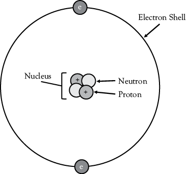
Figure 1.1 Atomic model of a helium atom, showing positions and charges of neutrons, protons and electrons.
Table 1.1 Charges and masses of subatomic particles
|
Subatomic particle |
Charge |
Relative mass |
|
Proton |
+ |
1 |
|
Neutron |
0 |
1 |
|
Electron |
− |
0 |
Since opposites attract, negatively-charged electrons are held close to the nucleus by the force of their attraction to the positively-charged protons found there.
Electricity is the free flow of electrons through a conductor, or wire. We put those electrons to work when they power our loads, such as lights and motors. But if electrons are held in orbits by the force of attraction, how can we get them to flow freely to create electricity? That scientific breakthrough was made in 1800 by Italian Physicist Alessandro Volta, who discovered that if you introduce an external charge to an atom you can “eject” stable electrons out of their orbits and use them in a circuit.
His battery, known as a “Voltaic Pile,” stacked together discs of zinc and copper, separated by blotting paper soaked in brine. The zinc had a chemical reaction with the water in the blotting paper, known as reduction-oxidation (redox). The zinc oxidized, each atom of zinc lost two electrons that were then free to move as current through a circuit. This was a huge breakthrough in the history of electricity. Previous experiments had used friction to generate current, but the Voltaic Pile was the first battery that could supply free electrons for a circuit.1
Similar to water flow, electrons flow by “pump pressure,” or a voltage source, through a “pipe,” or conductor. Along the way those electrons encounter resistance, like obstructions on a path, and serve our loads. The electrons give up some of their energy by powering our loads and return to the voltage source. In Figure 1.2, when the switch is closed, wires conduct, moving electrons (electricity) from the voltage source (battery) to the electrical load (light bulb) and then back to the voltage source, encountering resistance along the way.
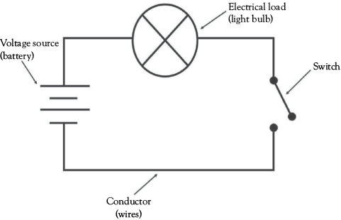
Figure 1.2 Simple electrical circuit showing a voltage source (battery), conductor (wires) and an electrical load (light).
These components of electricity, Voltage (V), Current (I) and Resistance (R), interact with each other in a relationship discovered by the 18th century German Physicist, George Ohm.
V = IR
Voltage, the electrical potential, is the product of current and resistance. The electrical potential of a circuit is based on its current (the flow of electrons), and its resistance (how hard it is for the electrons to flow). Resistance represents electrical potential “lost” in the form of heat.
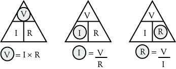
Figure 1.3 Ohm’s Law triangle. To solve for the missing variable cover it up with your finger.
Basic Circuit Types
Series—in a series circuit, the current flows along one path. In Figure 1.4, the resistors, which may be lamps, are placed in series. In a series circuit, the total resistance is the sum of the individual resistances.
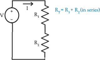
Figure 1.4 A series circuit showing two resistors connected to a voltage source.
For instance, let’s say you have a series circuit where the voltage is 12 volts, resistor 1 (R 1) is 50 ohms and resistor 2 (R 2) is 150 ohms. To find the total resistance (R T) you add the two resistors:
R1 + R 2 = 200 ohms
To find the current, using Ohm’s Law, I = V/R, thus:
I = 12 volts/200 ohms
= .06 amps * 1000 milli-amps /amp
= 60 milli-amps (mA)
In a series circuit, the total voltage is the sum of the individual voltages. An important concept in a series circuit is that if there is a fault with one load the entire circuit is open and all subsequent loads will not be powered (think of Christmas lights).
Parallel—on the other hand, a circuit that has multiple branches allows current to flow in branches parallel to those with faults. In a parallel circuit, like the one shown in Figure 1.5, the total resistance is the sum of the reciprocal of each resistance. This means that the total resistance is always less than the smallest individual resistance. This makes sense because more paths for electrons to flow means greater current. Greater current means less resistance, and indeed total current in a parallel circuit is the sum of the individual branch currents.
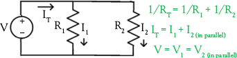
Figure 1.5 A parallel circuit showing two resistors in parallel branches connected to a voltage source.
Let’s take an example. If R 1 is 2 ohms and R 2 is 3 ohms, then the R T is 1/2 ohms + 1/3 ohms:
1/R T = 3/6 ohms + 2/6 ohms
= 5/6 ohms
Taking the reciprocal of 1/R T, the total resistance is thus:
6/5 ohms
= 1.2 ohms
Finding the total current, we would use Ohm’s Law, I = V/R. If the voltage is 6 volts, then:
I = 6 volts/1.2 ohms
= 5 amps
Given the branch currents, and that the voltage is the same across branches, an easier way to determine total resistance is to find the individual branch currents, sum them, and then find the total resistance, as shown below.

What About Magnetism?
On closer examination, the flow of electrons within a conductor is based not just on the repulsion and attraction of electrons, but on their interaction with magnetic fields. Magnets are elements with intrinsic properties that give them a magnetomotive force (mmf) similar to the voltage pressure in an electrical circuit. There are several conditions that must be met for a material to be magnetic, but they all result in the same thing: the material must be capable of aligning all its magnetic domains in the same direction, as shown in Figure 1.6.

Figure 1.6 The alignment of domains in a magnetic substance and misalignment of domains in a non-magnetic substance.
Electricity and magnetism can be transformed into one another. Electricity and magnetism are linked, resulting in the term electromagnetism. In Figure 1.7, you can see that if you run current through a wire, it generates an electromagnetic field. But it also works the other way: if you move a wire through an electromagnetic field, the field causes the electrons to move, generating current.
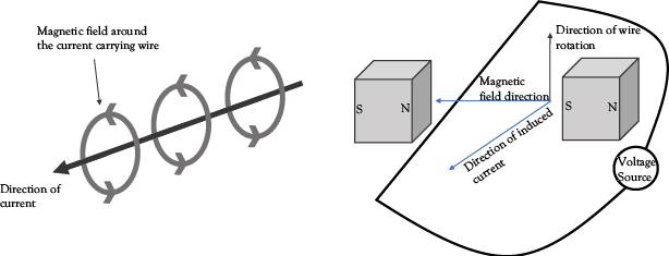
Figure 1.7 Generation of a magnetic field around a current-carrying wire, and the electromagnetic induction of current when a wire moves through a magnetic field.
How Is Voltage Generated?
Voltage is simply the amount of flux, “magnetic stuff,” a conductor can capture over time. Flux is the magnetic field, the strength of which is determined by the magnetic material, over a certain area. To get more voltage, add more field, area, or windings (turns of the conductor coil). The degree to which a conductor interacts with the magnetic flux in its vicinity is called the flux linkage. If you are a science fiction geek like me, upon hearing the term flux you may have thought of the flux capacitor from Back to the Future—who knows, perhaps someday we will discover flux can warp the space-time continuum!
Michael Faraday’s Law of induction, demonstrated in Figure 1.8, shows us that the amount of voltage generated on a coil is based on the amount of magnetic flux a current-carrying conductor captures over time, and the number of conductors. The more flux, the greater the induced voltage. The more coils, the greater the induced voltage.
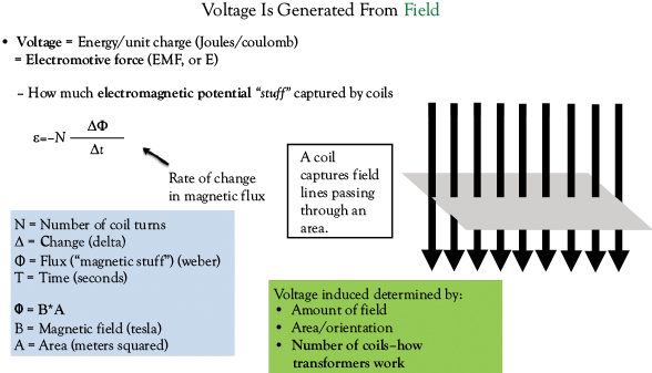
Figure 1.8 Generation of voltage from a magnetic field.
Rules of Thumb
Power Rule: Similar to the Ohm’s Law triangle. As shown in Figure 1.9, just cover up the missing variable to solve.

Figure 1.9 The power law triangle.
Power = Voltage * Current
Ohm’s Law Wheel: Combining Ohm’s Law and the Power Law. Cover up the variable you seek in the inner circle (P, V, I or R), and solve using one of the three equations in the respective quarter circle.
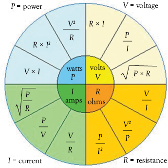
Figure 1.10 Ohm’s law wheel.
Source: Wikimedia Commons2
A Note on Calculations: Railway Method (Dimensional Analysis) for Units Conversion
Always remember the units! Engineers must convert units all the time, and most errors are made from unit conversions gone wrong. In order to ensure we are clear on units, the railway method, so-called because the multiplication and division symbols come together to look like train tracks, is a simple way of converting. Note we always write out the units and treat them as factors that can be cancelled.
For instance, if we want to convert 10 feet into inches:
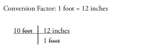
The feet cancel and we are left multiplying 10 * 12 = 120 inches.
Should there be more or less inches than the equivalent in feet? More! Because there are 12 inches in 1 foot. Also, we should be left with the unit inches.
When dealing with multiple unit conversions this method is very useful. For instance, if we want to convert 3.5 yards to millimeters (mm):
Conversion Factors:
1 yard = 3 feet
1 foot = 12 inches
1 inch = 25.4 mm
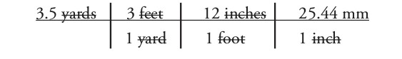
Therefore, we have 3.5 * 3 * 12 * 25.44 = 3200.4 mm.
Common sense check: There are 3 feet in a yard, 12 inches in a foot, and many mm in an inch, so we should end up with a much larger number. Check! The yards, feet, and inches should cancel out, and we should be left with mm. Check!
The Commercialization of Direct Current Electricity
In the span of human history, electricity has only been around for the blink of an eye, and its tale is storied. Consider the “War of Currents” between Thomas Edison and Nicola Tesla. The story begins with a young Tesla working for Edison, and ends with Edison purportedly electrocuting animals to prove the dangers of high voltage Alternating Current (AC).
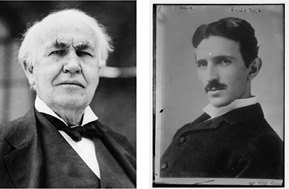
Figure 1.11 Left: Thomas Edison, inventor of the indoor incandescent light bulb and defender of Direct Current, and right, Nikola Tesla, inventor of Alternating Current and the AC motor.
Source: Library of Congress3
Industry was quick to realize the potential of “harnessed electricity.” In 1878, Edison produced the indoor incandescent light. At the time, batteries and Direct Current (DC) generators were being used to power arc lighting systems, which is luminescent gas ignited by a pulse of voltage, and, believe it or not, battery-powered electric vehicles.
By 1882, Edison was providing electrical power to 59 customers in Manhattan, upending the incumbent gas light utilities. However, long-distance transmission of Edison’s DC supply was proving impractical.
Edison asked a young Serbian employee, Nicola Tesla, to solve this problem. Unfortunately for Edison, Tesla’s research led him to believe that DC would never work for mass electrification. In DC production, the electrons pushed out by a power station are the same ones that enter customers’ lights and machines, requiring loads to be as close as possible to the voltage source to reduce power loss.
Tesla’s solution was to make the electrons in conductors “jiggle” back and forth, delivering power without themselves traveling to each customer. With AC, Tesla figured that electricity could be generated away from population centers and sent over great distance.
Transforming AC Voltage
Twinkle Twinkle Little Star, Power Equals I Squared R: Recall Ohm’s Law Wheel. We use AC power to transmit electricity over great distances since it can be easily transformed to have high voltage and low current. Greater current means more power loss due to friction requiring larger wires, so we use AC power to reduce the current and reduce power loss and costs.
- AC voltage is easily transformed, making it convenient to send over large distances.
- AC power can be sent in 3 phases, maximizing the amount of power delivered to the load.
- The size of a wire is related to its ability to conduct current.
- Like water in a pipe, a smaller wire can carry less current than a larger wire. Larger wires mean more material and cost.
By generating electricity at a low voltage, and then using a step-up transformer to increase the voltage and decrease the current, we can use smaller wires to transmit power over great distances, and reduce heat loss.

Figure 1.12 Thermal imaging of an electrical panel, demonstrating a wire’s ability to conduct current and the resulting heat loss. Photo by author.
Tesla, who today is known as the inventor of the AC motor and the modern system of electrical power generation and transmission, had a vision of electricity in every home and he understood that to make this happen, great amounts of power would be needed.4 At the time, batteries were limited and expensive, but a new technology, the engine in motors and generators, was being rolled out on a large scale.
The Operation of Motors and Generators
Driven by fuel combustion as its prime mover, the engine in a car combusts fuel to turn a rotor that propels the vehicle. This engine could also be used to generate AC electric power as part of a generator. A generator is comprised of a rotor (rotating part) and a stator (stationary part). Mechanical power is transferred to electrical power by an engine turning the moving rotor and using induction to pass off the electromotive force in the rotor to wires in the stator to produce electricity.
Recall from Faraday’s Law of induction—an electromagnet produces a magnetic field. When a coil passes through that field it generates current on the wire. When current passes through a coil it generates a field. The field induces a voltage on other coils. In a generator like the one shown in Figure 1.13, a field on the rotor windings induces a voltage and current in the stator windings. In a transformer, primary coils produce a field that induces a voltage in secondary coils.

Figure 1.13 Diagram of an Alternator producing AC electrical power.
This moving rotor creates a sine wave that produces the “jiggling” motion of the AC electrons, constantly moving back and forth between positive and negative voltage and current.
The windings that initiate energy transfer are known as field windings. The windings that receive energy are known as armature windings. In a generator, electrical feeders run from the stator to the switchboard where the electricity is directed to loads.
The First Law of Thermodynamics states that energy cannot be created nor destroyed, only transformed. Generators convert mechanical energy to electrical energy, passing the energy of the moving rotor to the stator. Motors work by the same principle, just in reverse—electrical energy is transformed into mechanical energy. In a motor, electricity in the stator generates a field that moves a rotor.
Power always flows from field windings to armature windings. In a motor, the field windings are located in the stator and the armature windings are in the rotor. In a generator, the field windings are in the rotor and the armature windings are in the stator. In the following diagram, “mechanical parts” are the rotor and stator, think of them as the physical equipment, and “electrical parts” are the field and armature windings. The parts are the same in both a motor and generator, the only difference is the flow of energy.
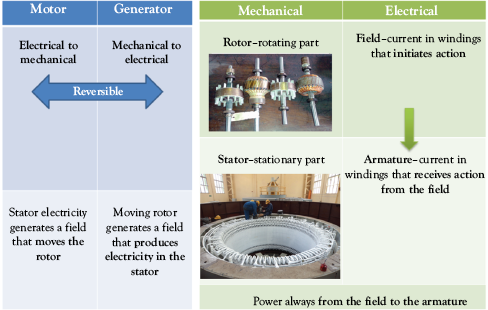
Figure 1.14 Reversibility of motors and generators. The windings are copper or aluminum. The electromagnetic core is iron. Image sources: Various types of rotors (Wikimedia Commons) and Stator for hydroelectric power plant (Wikimedia Commons).
The Commercialization of AC Electricity
Around the same time as Edison was pushing DC lighting, the industrialist George Westinghouse was researching AC and transformers. By the mid-1880s, Westinghouse had developed the induction coil for AC power transformation, and the fight between AC and DC, or the “War of Currents” was in full swing.
Westinghouse bought some of Tesla’s patents, and began installing AC generators around the U.S., expanding AC electricity to remote areas Edison could not reach, and undercutting Edison in areas where he was already established. With his business under threat, Edison turned his efforts to depicting AC as a technology with dangerously high voltages. He secretly funded an inventor to use AC in his design for an electric chair, and used high voltage AC electricity to execute dogs, calves and horses. It was still Westinghouse, however, who won the coveted contract to power the 1893 Chicago World Fair, using Tesla’s AC electricity.5
Another Perspective on Why Edison Was Against Alternating Current
Electricity is the thing. There are no whirring and grinding gears with their numerous levers to confuse. There is not that almost terrifying uncertain throb and whirr of the powerful combustion engine. There is no water circulating system to get out of order—no dangerous and evil-smelling gasoline and no noise.
—Thomas Edison
In retrospect, Edison’s vision for the future may be viewed as ahead of his time. Even back in the 1900s, he knew fossil fuels were polluting our environment. Solar cells produce DC and batteries store DC. If the future was to be built on AC and fuel generators, then electric vehicles, solar, and batteries would have no place. This incompatibility is at the crux of the current obstacles for many renewable energy sources. Clearly AC won the “War of Currents.” Today, developed countries have AC infrastructure and fossil fuels are the predominant source.
The Development of Electric Grids
Edison and Westinghouse ran early examples of private or Investor-owned Utilities (IOUs). During the early 20th century, IOUs emerged throughout the country. At the same time in Europe, scientists and business owners were developing their own power stations and energy supply systems. Over time, companies cooperated with each other to balance the load on power stations and ensure full supply at peak times. Eventually, these systems merged into what we now call the “grid”– the integrated network of power stations and transmission infrastructure that provides consumers with electricity on demand.
USA
By the beginning of the 20th century, America had more than 4,000 individual private utility producers, greater in number and diversity than Europe. When these companies began to cooperate with each other in larger grid systems, the large size of the US and the diversity of geographies and providers led to the creation of three connected, yet distinct, electrical systems:
- The Eastern Interconnection (mostly east of the Colorado Rockies)
- The Western Interconnection (mostly west of the Colorado Rockies)
- The Electric Reliability Council of Texas
Within each system, smaller local grids were connected together and the flow of power managed by a balancing authority, an entity that coordinates electricity generation and transmission in a region.
The layout of the US electric grid was informed by a low population density, especially in rural areas, and high individual electrical loads. Energy from power stations is distributed throughout the U.S. via medium to high voltage primary cables, or transmission lines. When these cables reach an area of population density/electrical load, a small distribution transformer is installed, often atop a pole above ground. Secondary cables, or distribution lines, then conduct the stepped-down electricity to a few consumers over short distances. This grid pattern has a higher load capacity per mile of circuit compared to European grids, and is suited to America’s large distances between energy consumers. There is a distribution transformer for every few houses and when new houses or other electrical loads are built, it is easy to add a new, small step-down transformer and secondary cables to the system.6
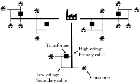
Figure 1.15 Schematic of the North American grid system.
Europe
Europe’s small countries and political structures led to the rapid development of national energy boards, standardization of supply, and nationalization of each country’s energy grid. In the UK, the first steps toward a standardized energy system were taken in 1919, and the national grid began operation in 1938. In France, the densely-connected national grid was nationalized in 1946.
Europe’s dense population and lower load density than the U.S. meant that space was a commodity. Fewer step-down transformers were built and were usually placed underground or inside vaults. In Europe, electricity is carried to consumers via an extensive network of secondary, 220 volt underground cables. The use of 220 volts, as opposed to the 110 volts in the U.S., means the secondary lines can deliver power to customers farther from the step-down transformer. This means less transformers are needed. Also, higher voltage cables means less current and smaller (cheaper) wires can be used.
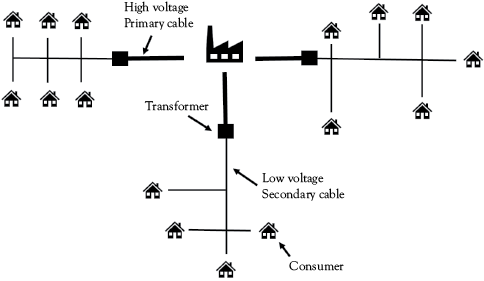
Figure 1.16 Schematic of the European grid system.
Both in the U.S. and Europe, a drive for greater profits through economies of scale pushed utilities to become vertically-integrated regional monopolies, owning all parts of the power supply chain—the generation, transmission, and distribution. Beginning in the late 1970s, however, regulators began to restructure utilities to lower the cost of electricity and encourage greater environmental protection from a diverse supply of generators. Today, many utilities no longer own the majority of their generation, and purchase their power through power purchase agreements (PPAs) with generators.
As part of this restructuring, the U.S. and Europe began to deregulate the electricity sector in the 1990s, allowing consumers to choose an electricity provider that generates or markets electricity other than their utility. In this case, the utility still owns and operates the transmission and distribution system. Deregulation was done, in part, to promote renewable energy adoption while reducing rates.
Renewable Energy on the Rise
There are three types of conventional generators. Baseload power is always on and forms the backbone of our energy supply. These sources are primarily nuclear power and combined cycle power plants. The next category is cycling units, mostly gas and oil steam plants. They alternate their output during the day and can ramp production up or down quickly over a range of 25 to 100 percent of their capacity. These cycling units provide the grid with flexibility and are particularly important for facilitating the integration of variable solar and wind resources. When demand spikes, a third category, peaker gas turbines are turned on and rapidly brought to full load.

Figure 1.17 Electricity generation by fuel source in major countries and the world in 2015.
Source: IEA 2015. All Rights Reserved.7
Despite their variability, renewable energy is comprising an increasingly significant share of global energy production. This trend is intensifying. In 2017, 18 percent of all electricity in the U.S. came from renewable sources, up from 5 percent in 2015, and solar and wind projects made up 62 percent of new power generation investment.8
Chapter 1 Questions
- If the voltage in a series circuit is 12 with resistance 1 of 40 ohms and resistance 2 of 20 ohms, what is the current in milliamps (mA)?
- In a parallel circuit, if the resistance of branch 1 is 4 ohms and the resistance of branch 2 is 2 ohms, and the voltage is 8, what is the current?
- Using the railway method, convert 10 amps to milliamps (mA).
- Using the Ohm’s Law Wheel, how much power in watts is in a circuit with 10 amps of current and 12 ohms of resistance?
- What is the voltage of a circuit with a 2.2 kilowatt power source and 20 ohms of resistance?
- Explain how electricity is generated. What is meant by the reversibility of motors and generators?
- Why do you think Edison ultimately lost the AC/DC power battle? Do you think there is any way that he could have succeeded?
Chapter 1 Glossary
Conductor: a material that electrons/current can flow through. Most conductors are metals.
Current: the free flow of electrons through a conductor or wire. Unit is amps.
Deregulation of Electricity: Consumers purchasing electricity from providers other than their utilities, although the utilities still own and operate the transmission and distribution system.
Electrical Load: the part of a circuit that draws or consumes electrical power.
Electromagnetism: the interaction between electric and magnetic fields.
Electromotive Force: the difference in electrical potential that results in an electric current.
Flux linkage: how much a conductor interacts with magnetic flux.
Magnetic Flux: The amount of magnetic field passing through a surface area.
Power: the amount of energy transferred (work) per unit of time. Unit is watts.
Power Purchase Agreement (PPA): A key element of project finance, the contract between an energy-generating party and an energy-buying party, setting out the cost of the power transferred.
Resistance: how difficult it is for electrons/current to flow through a conductor. Unit is ohms.
Voltage Source: analogous to a pump, the entity that creates the force to power electrons through a circuit.
Voltage: The size of the force powering electrons through a circuit. Also known as the difference in electrical potential. Unit is volts.
References
1. MIT Libraries logo MIT Libraries. n.d. https://libraries.mit.edu/collections/vail-collection/topics/electricity/the-voltaic-pile/
2. Wikimedia Commons. n.d. Attribution: VampireBaru, https://en.wikipedia.org/wiki/File:Ohm%27s_law_formula_wheel.JPG This file is licensed under the Creative Common Attribution-ShareAlike 3.0 Unported License.
3. Nicola, T. 1890. “Library of Congress.” http://loc.gov/pictures/item/2014684845/
4. King, G. 2011. “Edison vs. Westinghouse: A Shocking Rivalry.” Smithsonian.com, October 11, 2011. https://smithsonianmag.com/history/edison-vs-westinghouse-a-shocking-rivalry-102146036/ (accessed September 12, 2018).
5. “Tesla, Life and Legacy - War of the Currents.” PBS, https://www.pbs.org/tesla/ll/ll_warcur.html
6. Von Meier, A. 2006. Electric Power Systems a Conceptual Introduction. Hoboken, NJ: Wiley-Interscience.
7. IEA Statistics. https://iea.org/statistics/?country=WORLD&year=2016&category=Energy%20supply&indicator=TPESbySource&mode=chart&dataTable=BALANCES
8. 2018 Sustainable Energy in America Factbook. Report. Bloomberg New Energy Finance.