Model 3: Community-Scale Generation and Microgrids
Community generation and microgrids are becoming an increasingly popular alternative to utilities and distributed energy resources. These systems serve a collection of individual households, businesses or industrial facilities. From the perspective of the utility, they are simpler to manage than individual producers because they aggregate prosumers and reduce points of interconnection. For the customer, grouping individuals compounds purchasing power and provides leverage with generators and the utility.
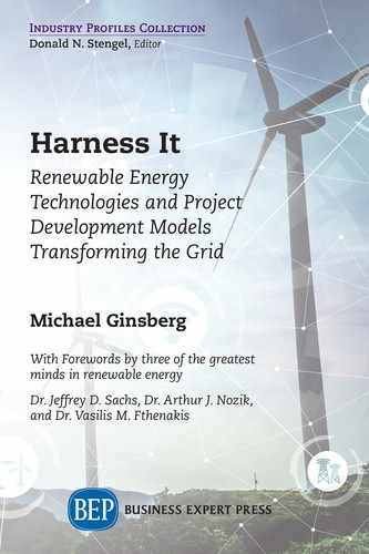
In addition, combining solar and wind produces more consistent power because they are complementary—wind output is greatest at night and solar production is highest in the middle of the day. Some of the multiple generation sources discussed in Chapter 2 are shown in Figure 5.1, a hybrid system, which connects various energy sources and storage for more reliable power for a facility.
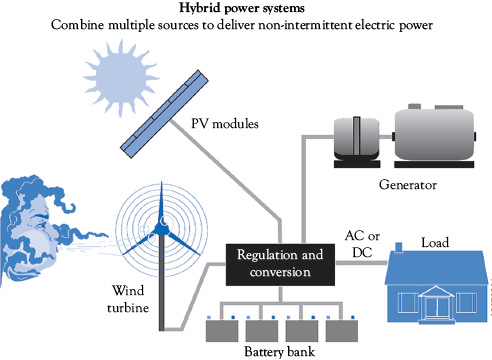
Figure 5.1 Hybrid household power system. Shown above is a residential system with various generators, including a wind turbine, solar PV modules, a generator, and a battery bank for energy storage.
Source: Small Wind Guidebook. US Department of Energy.1
Community Generation is a solar, wind, micro-hydro, fuel cell or hybrid energy system whose output is shared by the residents of the immediate area. There are a few ways of implementing such projects. In a Utility-Sponsored model, a utility owns and/or operates a system with voluntary participation. With the Special Purpose Entity model, individual investors finance the project. In the Non-Profit model, community groups fund the project.
|
Community Generation |
|
|
Model |
Sample Program |
|
Utility-Sponsored |
The Sacramento Municipal Utility District (SMUD) contracts with solar developer enXco to offer customers solar energy from a 1 MW PV system. Customers pay a fixed monthly fee based on the amount of PV capacity desired (0.5 to 4 kW) and their average electricity consumption. |
|
Special Purpose Entity |
The Clean Energy Collective (CEC) allows for individual membership of a 78 kW PV array in Western Colorado’s Holy Cross Energy Service Territory. The CEC leases the land from Holy Cross Energy and has a PPA that will rise with regular utility rate increases. CEC uses a software that directly integrates with the utility’s billing system to apply monthly member credits to individuals’ accounts. |
|
Non-Profit (Cooperatives) |
In Brighton, UK, members of the local community can buy shares in the Brighton Energy Cooperative, a type of cooperative known as a Community Benefit Society. This capital is then used to build solar PV capacity on local rooftops and other prime locations. Until now the business model has been based on feed-in tariffs but the success of cooperatives like the Brighton Energy Cooperative mean that the organization now sells energy on the open market. Rather than directly receiving the energy generated by the co-op, members receive a 5–7 percent return on their investment.2 |
Community Generation Project Development
Similar to the process discussed in Chapter 3, community generation projects involve a series of steps. NREL defines the lifecycle of a community project in the following phases: feasibility, project development, construction, operations and maintenance, and decommissioning.3

Figure 5.2 Lifecycle of a community generation project as defined by NREL.4
In the feasibility phase, the team conducts a technical assessment of the solar or wind resource, assesses financing options, and obtains the community’s support. During project development, the site design and financing are finalized. Also, environmental permits are obtained, the interconnection agreement established, and contractors hired. During construction, the architectural and engineering firm and contractor collaborate to realize the design. Often overlooked, operations and maintenance involves an ongoing plan for inspections and remote monitoring for verification of performance.
Critical to operations is software that keeps track of members’ respective share of the energy. Software as a Service (SaaS) firms have emerged that specialize in managing shared renewable energy assets. Finally, the site must be decommissioned, or removed at the end of its life, with consideration to recycling of the spent modules or turbines.
Microgrids
When it comes to a utility figuring out how to manage this wide, dynamic set of resources and control points, the only way they can do that efficiently is to break their networks down into small nodes that is, microgrids—and then add a level of control on top of it.
—Dave Pacyna, senior vice president of Siemens Energy’s North American
Microgrids are small, interconnected energy systems that contain a mix of distributed energy resources, storage units and associated loads within a localized grid, forming an island in the central grid. This energy system can operate as part of the wider energy system, but if there is an issue with the wider grid, the microgrid can separate itself and operate independently, ensuring continued energy for its customers.
Comprised of multiple resources, microgrids are more reliable than an individual distributed generator by itself, and provide benefits to the grid, since they can be dispatched to export power to local customers during peak demand conditions. Also, microgrids can alleviate or postpone distribution system upgrades.5
As shown in Figure 5.3, a microgrid consists of several components:
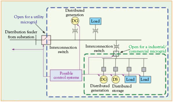
Figure 5.3 Microgrid and its components (electrical loads, distributed generation, distributed energy storage, control systems, and an interconnection switch linking to the central grid).
Source: “Making microgrids work”, IEEE Power & Energy Magazine. Kroposki, et al. May-June 2008.6
- The distributed energy resources (DERs) (aka Distributed Generation-solar, wind, hydro, biomass, and others).
- The electrical loads (customers and potential storage).
- A distribution network connecting DERs with the loads.
- Internal sensors and meters measuring and protecting the microgrid energy supply.
- An interconnection switch, or static switch, and a digital signal processor, synchronizing power and voltage with the central grid.
- Computer systems (often cloud based) for metering, tariffs, and optimization of energy production and demand within the microgrid.
History of Microgrids
In 1998, the U.S. government sponsored the creation of the Consortium for Electricity Reliability Technology Solutions (CERTS), a group of energy stakeholders from the private sector, government research laboratories, and academia. One of the main objectives of CERTS was to find a solution to the issue of long, wide-scale energy blackouts across North America, resulting from extreme weather events, operator errors, and malfunctioning technology within the aging grid.7 CERTS’ research on the problem proposed the “CERTS MicroGrid Concept” as a solution.8
CERTS is essentially a protocol for communication between DERs and other components of microgrids. CERTS-compliant products are designed to be versatile in interacting with other components and the grid. For instance, to ensure that the connect-disconnect transition with the wider grid is seamless in the face of grid interruptions, increase the reliability of the islanding mode, and guarantee continued connection for the electrical loads within the microgrid, CERTS does not use a master controller. Rather, they ensure components can operate “peer to peer” so that when an individual component fails, the rest of the system can continue operating. CERTS-compliant systems are also cost-effective since component DERs are compatible with one another via a “plug and play approach” that makes them easily scalable with fewer electronics.
Microgrid Design
Microgrids exist at a range of sizes to ensure energy security for a variety of electrical loads, from a single business, federal facility or laboratory to a residential district.
The amount of the load served by the microgrid defines its purpose. Microgrids covering 30 to 60 percent of loads provide energy assurance to critical needs while those covering 100 percent of loads provide energy independence. They can even go a step further and provide 100 to 300 percent of the necessary electrical load, generating revenue.9
The design of a microgrid depends on load requirements, generation mix, components, and its ability to island itself from the wider grid. A microgrid is highly versatile. Depending on the central grid and DER production, a microgrid may draw solely from the central grid, a mix of DERs and the grid, or from the DERs and energy storage alone. This flexibility entails design challenges in terms of the microgrid’s energy short circuit capacity, the need for bi-directional energy flow, and the quality of the energy generated. The second case study in this chapter explores these challenges in detail.
Short Circuit Capacity: The central grid uses large, synchronous, rotating power generators, which have a large short-circuit capacity. Standard overcurrent protection is designed with this in mind. In contrast, renewable generators must be linked, or coupled, to the microgrid via inverters, which can be damaged by high currents. Thus the inverters are self-limiting in terms of how much current they can conduct, with a limit only marginally above the level at which they normally conduct (roughly 120 percent of inverter-rated current). When a microgrid is in island mode, the short circuit capacity of the entire system is reduced. Without adequate planning and system design, this can result in frequent system interruptions.
Bi-directional energy flow: Unlike a traditional centralized grid system, where energy flows only one way (from generating power stations to consumers), the flexible nature of energy production and consumption patterns in a microgrid requires bidirectional energy flow, including but not limited to:
- From the central grid to electrical loads within the microgrid
- From the microgrid to microgrid storage and the centralized grid, during periods of over-production
- From DERs and storage to microgrid electrical loads while in island mode
Power Quality: Power within a centralized grid is produced at a constant and predictable rate, controlled by the power plant operators. Production from DERs is less predictable and can lead to fluctuations in available power that cannot be increased to meet surging electrical load. There may be additional fluctuations in harmonics, frequency, transients and voltage. To ensure no damage occurs to the microgrid, its components or electrical loads, these parameters must be monitored and managed to maintain a stable frequency and voltage.
Power Control: Traditional rotating, synchronous power generation is grid forming, which means that it naturally assists in the creation and regulation of the voltage and frequency of the power within the grid. Inverter-based DERs tend to be grid-tied, which means that they feed energy into the grid, but still rely on synchronous power generation to create and maintain the grid voltage and to stabilize frequency. This causes issues for certain loads in a DER-only microgrid in islanding mode. However, newer DER inverters, called Inverter-Based Generators (IBGs), are able to provide a grid-forming function in an islanded microgrid.10
Use of the IBGs allows for the nearly instantaneous switching of voltage, current and frequency between grid-tie and islanded mode. For instance, in Figure 5.4, the Main grid line indicates the steady state voltage from the main grid at 230 volts, while the microgrid line indicates the steady state of the microgrid at just under 215 volts, which would be experienced during the islanded mode. When grid-tie is re-established it takes approximately two seconds, in this study, for the microgrid voltage to synchronize with the central grid.

Figure 5.4 Microgrid synchronizing voltage with the central grid during transition from islanded to grid-tie mode.
Source: Papadimitriou, C.N., et al. “Control strategy for seamless transition from islanded to interconnected operation mode of microgrids”. Journal of Modern Power Systems and Clean Energy. March 2017.11
In addition, IBGs offer other support for the grid, such as supplying reactive power that the grid is accustomed to receiving from conventional generators but is not provided by solar PV systems. Reactive power, which is necessary for motors, can be provided by adjusting the inverter’s power factor.
Emerging Trends: Beyond niche projects, stakeholders are beginning to realize the value of community projects and microgrids. With the advent of information communication technologies and monitoring/metering equipment, facilities unable to host their own generators can invest in a microgrid in another location and sell its power and services, such as voltage and frequency support, to the grid through virtual net metering. In addition, fleet microgrids, or collections of microgrids working in tandem can enable entire communities and potentially cities to become power generators.
Case Study 1: Leapfrogging the Traditional Electrical Grid in Africa Through Microgrids
Richard Driscoll, Former Branch Chief, Office of Global Change, U.S. Department of State
Renewable energy has allowed many in the developing world to “leapfrog,” or skip over, the centralized electrical grid. In the last decade, technological and financial innovations brought energy to 130 million people in areas of the world the grid has not yet reached.12 Africa has been a leader in novel financing options to facilitate access to such systems, from two million users of solar home systems in 2011 to over 53 million in 2016.
East Africa received nearly 60 percent of the total global investment in off-grid solar in 2017. Kenya has been a leader in developing and implementing a form of Solar as a Service known as “pay-as-you-go” (PAYG). AzuriPayGo Energy provides off-grid solar energy to households throughout East Africa. The basic system includes a solar module, inverter, and mobile payment device, and provides sufficient power for lighting, mobile phone charging, and a radio.13 The consumer pays a small one-time fee for the installation of a solar PV system and then purchases scratch-off cards and uses their mobile phone to top-up their unit. After 18 months, the customer fully owns the system and can use it at no additional charge.
A survey showed that 85 percent of Azuri customers used kerosene lamps prior to installing the solar home system, but only 17 percent used kerosene afterwards. Azuri reports that the solar home system cut weekly energy spending by up to 50 percent. Azuri highlighted the economic benefits in Kitale, Kenya, where one farmer realized a 350 percent increase in her profits because, with lights, she could do her household chores after dark, freeing time in the day to increase her farming production. Similarly, a fishmonger from Kitale has been able to devote additional hours in the marketplace, which has resulted in a 250 percent increase in profits.14 The potential for replacing fossil fuel with renewable energy off-grid solutions is substantial. IRENA notes that households and small business around the world spend about $36 billion on fossil fuels for lighting, including about $10 billion in Africa alone.
M-KOPA, based in Nairobi, is one of the world’s leading “pay-as-you-go” energy providers for off-grid homes. Similar to Azuri, M-KOPA requires an initial deposit of $35, and daily payments of $0.50 for one year until the consumer owns the system.15 In Mugurameno in Zambia, Standard Microgrid has installed a solar powered microgrid for a community of 32 homes, businesses, and the local primary school.16
While the growth of decentralized renewable energy systems in Africa has helped millions, it is posing challenges for policymakers who must develop regulations for interconnection and integration with the national electrical grid.
Case Study 2: Integrating Solar PV and Wind with Diesel Generators
Microgrids combine various generators to provide reliability to a facility or community during a grid outage. The variability of solar and wind requires careful planning and foresight in the design of a microgrid. This is particularly important when the microgrid entails adding wind and solar to existing diesel generators used as backup for a facility.
Many facilities with existing diesel generators are now installing solar or wind energy systems to reduce their CO2 and other emissions. On one occasion, the author inspected a facility in Burkina Faso, West Africa that had just installed a 380 kW PV system to offset demand from the grid, and from the diesel generator currently used as backup during grid outages. No batteries or energy storage system were installed with the system. In Burkina Faso, blackouts are common, about 6 per day, and last an average of 1.5 hours.
Facility engineers quickly realized that during a grid outage the interaction between the PV system and diesel generator was suboptimal. When the utility power was lost, the PV inverter automatically disconnected due to anti-islanding precautions, and the diesel generator was initiated. Once the PV inverter sensed stable power, the PV system reconnected and supplied power to the facility’s loads. However, this caused the generator to fluctuate and operate at as low as 30 percent of its rated load.
Grid-tie PV systems and diesel generators are not designed to share the load. For one, PV inverters shut off during an outage to prevent back-feeding to utility lines. Another critical issue is that PV systems fluctuate based on the sun. This means that diesel generators will be forced to rapidly fluctuate their supply based on the PV output, and operate at low loads. At low loads, typically less than 60 percent of rated load, wet stacking occurs in diesel generators. This is a phenomenon in which fuel that is unburned due to the low load ends up in the exhaust pipe. This causes lower cylinder pressures, which lead to poor piston ring sealing and poor combustion. Incomplete combustion causes soot formation and fuel residues that clog the piston rings and pollute the exhaust. Another consequence is glazing, flash burning of the lubricating oil on the cylinder walls.17 Combined, this increases fuel consumption due to poor efficiency, and degrades the generator, shortening its life.
The simplest solution is an automatic shut-off that prevents the PV array from contributing output while the generator is running, although this would be economically disadvantageous, negating the benefit of the PV supply during outages. Another solution would be to use a natural gas generator, which burns at higher temperatures than diesel engines, and thus would have less unburned fuel while operating at low load. However, it is still not ideal to run a natural gas generator at low load.
Another solution to this problem would be to add energy storage. In systems with diesel generators, solar and battery storage, the batteries could provide consistent power during an outage. As discussed in Chapter 2, in a PV system with battery storage, batteries supply consistent power to either fully or partially cover a facility’s loads. Storage provides additional benefits as batteries can supply power at opportune times, when the PV output is low in grid-tie mode, or to partially or completely offset reliance on the backup generator.
Finally, the use of a “hybrid controller” would ensure the diesel generator operates above the minimum load required to maintain acceptable power conversion losses. With such a controller, PV supply is still used to reduce diesel consumption during outages, but limited to maintain the operating reserve of the diesel generator. Operating reserve, or spinning reserve, is defined as surplus capacity that allows the diesel generator to handle rapid variability in load or PV supply. It is important to reduce maintenance costs and prolong generator life otherwise subject to frequent start-stop cycles due to the varying PV output.
With a hybrid controller, there are two options during islanded mode. If there is a decrease in load demand, or an increase in PV supply equal to or above demand, the PV inverter is shut off. If there is an increase in load demand, or a decrease in PV output below the diesel generator’s minimum, the PV is allowed to contribute to load.
Figure 5.5 PV curtailment by hybrid controller during grid outage to maintain diesel generator (DG) minimum load. Note the DG production is not shown, but rather the load. PV production is shown at its maximum at noon. In this graph central grid power is lost at 13:30 and PV production is curtailed to allow the DG to run at minimum acceptable load.18
Source: Hybrid Control of Microgrid with PV, Diesel, Generator and BESS. International Journal of Renewable Energy Research.19
Thus, in islanded mode, the maximum allowable PV generation is determined by the load minus the minimum diesel generator capacity, as follows:
PVMax = Total Load – Diesel Generatormin
Such solutions are commercially available and include, among others, the Fronius PV System Controller.20
A Microcosm of the Grid: The interplay/optimization issues between diverse generators explored in this case study are illustrative of the challenges of integrating variable wind and solar energy with conventional “on demand” fossil-fuel generators. As such, the issues with integrating diverse generators in microgrids can be seen as a “microcosm” of the grid at large.
Combined cycle gas turbines (CCGT) are useful for mitigating the intermittency of renewable energy resources. CCGTs are highly efficient because in one cycle they burn natural gas and in the next the exhaust heat generates steam to spin a turbine. CCGTs are able to operate at low loads with high efficiency and few emissions, and can start and stop quickly, a feature known as fast ramping.
As more wind and solar comes onto the grid, the flexibility afforded by these generators will become increasingly valuable. Integrating variable renewable energy resources will require diligent foresight, planning, and coordination between developers, utilities and independent system operators. This will ensure the addition of wind and solar does not compromise the security of energy supply, or diminish its economic return. We will discuss grid integration and the shape of a renewable energy dominated future in Chapter 6.
Chapter 5 Questions
- What are the three models for a community generation project and how do they differ?
- What is a microgrid and what are its key components?
- What is the difference between a microgrid and an off-grid renewable energy system?
- Read the article(s) “Real-World Performance of a CERTS Microgrid in Manhattan” and/or “CERTS Microgrid Demonstration With Large-Scale Energy Storage and Renewable Generation”. Note these articles can be found in the endnotes or on the webpage for this book.* Summarize the article(s) in 1 to 2 pages.
- Explain the differences and similarities between models of renewable energy development 1, 2 and 3 that have been discussed in Chapters 3 to 5.
- Do you think a microgrid is needed or would be useful for the area in which you live? Why or why not?
Chapter 5 Glossary
Community Generation: a solar, wind, micro-hydro, fuel cell, or hybrid energy system whose output is shared by the residents of the immediate area.
Inverter-Based Generator (IBG): unlike conventional generators with rotational inertia through the movement of a rotor, solar PV outputs DC at a dissimilar frequency and voltage to the grid. IBGs “clean” the DC output of the PV array and output AC to the grid as a pure sine wave.
Microgrid: a small, interconnected energy system containing a mix of DERs, storage units, and associated loads within a localized grid, forming an island in the central grid.
References
2. Brighton Energy Cooperative. 2018. “Community Energy—Invest in Renewables to Support Your Community.” https://brightonenergy.org.uk/community-energy-build-community/ (accessed September 16, 2018).
3. NREL. November 2010. “A Guide to Community Solar: Utility, Private and Non-profit Project Development.” https://nrel.gov/docs/fy11osti/49930.pdf
5. U.S. Department of Energy. 2018. “How Microgrids Work.” https://energy.gov/articles/how-microgrids-work (accessed September 16, 2018).
7. “Microgrids as Risk Mitigation for Extreme Weather.” Electric Light & Power, March 01, 2013. https://elp.com/articles/print/volume-91/issue-2/sections/microgrids-as-risk-mitigation-for-extreme-weather.html (accessed September 16, 2018)
9. Roach, M. 2014. “Community Power and Fleet Microgrids: Meeting Climate Goals, Enhancing System Resilience, and Stimulating Local Economic Development.” IEEE Electrification Magazine 2, no. 1, 40–53. doi:10.1109/mele.2013.2297011. https://ieeexplore.ieee.org/document/6774559
10. Boutin, V., V. Ignatova, J. Philippe, R. Heliot, Y. Harriot, A. Haun, and V. Wagner. 2017. “How New Microgrid Technologies Enable Optimal Cooperation Among Distributed Energy Resources.” Report no. 998-2095-03-15-17AR0_EN. Schneider Electric. https://schneider-electric.com/en/download/document/998-2095-03-15-17AR0_EN/ (accessed September 16, 2018).
11. Papadimitriou, C.N., V.A. Kleftakis, and N.D. Hatziargyriou. 2017. “Control Strategy for Seamless Transition from Islanded to Interconnected Operation Mode of Microgrids.” Journal of Modern Power Systems and Clean Energy 5, no. 2, pp. 169−176. https://link.springer.com/article/10.1007/s40565-016-0229-0
13. “AzuriPayGo Energy | Africa.” UNFCCC, https://unfccc.int/climate-action/momentum-for-change/financing-for-climate-friendly/azuri-paygo-energy (accessed December 04, 2018).
14. Azuri Technologies. June 06, 2017. “Katherine and Suzanne: Housewives, Mothers, Business Women.” http://azuri-technologies.com/case-study/katherine-and-suzanne-housewives-mothers-business-women (accessed December 04, 2018).
15. M-KOPA Solar. April 20, 2018. “Battery Technology Energising Off-grid Power Solutions in East Africa.” http://m-kopa.com/battery-technology-energising-off-grid-power-solutions-in-east-africa/ (accessed December 04, 2018).
16. “Mugurameno.” Standard Microgrid, http://standardmicrogrid.com/projects/mugurameno (accessed December 04, 2018).
17. Aurora Generators. May 20, 2016. “What Happens to Engines Running Without Sufficient Loads.” https://auroragenerators.com/blogs/generators/119916609-what-happens-to-engines-running-without-sufficient-loads
20. “Fronius PV Genset Easy Solution.” Fronius, https://fronius.com/en/photovoltaics/products/all-products/solutions/system-solutions/fronius-pv-genset-easy-solution/fronius-pv-system-controller
* Panora, R., J.E. Gehret, M.M. Furse, and R.H. Lasseter. “Real-World Performance of a CERTS Microgrid in Manhattan.” IEEE Transactions on Sustainable Energy 5, no. 4, 1356−1360. https://ieeexplore.ieee.org/document/6754189
Alegria, E.,T. Brown, E. Minear. and R.H. Lasseter. 2014. “CERTS Microgrid Demonstration with Large-Scale Energy Storage and Renewable Generation.” IEEE Transactions on Smart Grid 5, no. 2, 937−943. https://ieeexplore.ieee.org/document/6670071