
Functional Properties
High-entropy alloys have promising functional properties for a wide range of applications. A number of functional properties could be required in different applications. In this chapter, we focus on some basic functional properties including diffusion barrier, electrical, thermal, magnetic, hydrogen storage, irradiation resistance, and catalytic properties. Properties, alloy composition, processes, crystal structure, and microstructure will be correlated to give a better understanding of the phenomena and mechanisms. It is found that further composition design and process selection are feasible to tune functional properties for specific purposes and applications. A few reports are also available on functional properties such as biomedical, antibacteria, EMI shielding, antifingerprint, antisticky, and hydrophilic and hydrophobic performances, which are not included in this chapter.
Keywords
Diffusion barrier; electrical resistivity; magnetic property; hydrogen storage; catalytic property
9.1 Introduction
Many studies on HEAs are focused on the relationships between microstructure and mechanical properties. A few investigations are reported on the functional properties of these alloys. These include behaviour of HEAs as diffusion barrier, electrical, thermal, magnetic, hydrogen storage, irradiation resistance, and catalytic materials. These properties are also affected by their unique structural feature, that is, a multicomponent solid solution. The properties reported are encouraging and promising for different functional applications. Attempts are being made to take advantage of the encouraging functional properties of these HEAs in applications such as biomedical, antibacteria, electromagnetic interference (EMI) shielding, antifingerprint, antisticky, and hydrophilic and hydrophobic properties.
9.2 Diffusion Barrier Properties
One of the major challenges in the miniaturization of modern microelectronic devices is to develop future high-performance diffusion barrier materials (International Technology Roadmap for Semiconductors, 2009). When Cu is incorporated into Si, adverse effects including the formation of deep trap levels that cause serious device degradation and failure occur. The metallic barriers between Cu and Si are expected to fail around 550–650°C whereas ceramics fail around 700–800°C. In this aspect, HEA alloy barriers and HEA nitride barriers have shown improved temperature capability (Tsai et al., 2008b,c, 2011; Chang et al., 2009).
Metal barriers fail at lower temperatures due to two main reasons: (1) enhanced diffusion of Cu through barrier grain boundaries; or (2) reaction between barrier metal and Si (Tsai et al., 2011). The first problem can be alleviated by using amorphous ceramics, TaSiN is a classic example. However, in the case of metallic barriers, this strategy is not effective because many amorphous metal barriers crystallize below 550–650°C. Thus, the low structural stability of metals renders them ineffective in preventing the diffusion of Cu. Even those with extremely high melting points, such as W (3407°C), Ta (2996°C), and Mo (2617°C) start to react with Si at around 550–650°C. The second problem of metallic barriers, on the other hand, is due to their low chemical stability and reaction with Si. Thus, a better metal barrier has to maintain its amorphous structure and its inertness to Cu and Si up to temperatures higher than 650°C.
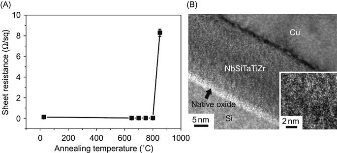
Based on this consideration, Tsai et al. (2008b) designed two suitable HEA alloy compositions for diffusion barrier. The first one is an octonary AlMoNbSiTaTiVZr HEA barrier of 100-nm-thick incorporated into the Cu/HEA/Si sandwich structure. It can prevent interdiffusion of Cu and Si at 700°C up to 30 min. Through further composition design, a 20-nm-thick NbSiTaTiZr diffusion barrier capable of preventing the interdiffusion and reaction between Cu and Si at 800°C up to 30 min was developed as shown in Figure 9.1 (Tsai et al., 2011). These results are comparable to many ceramic barriers. The superior performance of NbSiTaTiZr is owing to the higher structural stability of its amorphous structure and higher chemical stability against reaction with Si substrate as compared to conventional metal barriers. The structural stability comes from the low driving force (0.76 kJ/mol) for crystallization of amorphous phase, the large atomic size difference enhancing the stability of amorphous structure, and the slow diffusion kinetics due to four refractory elements and higher atomic packing density in the amorphous structure. The chemical stability comes from its lower free energy level. It was calculated that when unalloyed NbSiTaTiZr reacts with Si to form silicides, the formation enthalpy is 120.5 kJ/mol. However, the driving force for the silicide formation in NbSiTaTiZr is only 76.7 kJ/mol. Thus, the driving force for silicide formation from the alloy is 36% lower than that from pure elements (Tsai et al., 2011).
Tsai et al. (2008a) developed 70-nm-thick nitride diffusion barrier of (AlMoNbSiTaTiVZr)50N50 which has an amorphous structure that successfully prevents the reaction between copper and silicon when annealing at 850°C for 30 min. Its amorphous structure remained even after this annealing treatment. The excellent thermal and structural stability for preventing the silicide formation was attributed to the large lattice distortion and limited diffusion. Chang et al. (2009) developed an ultrathin quinary nitride film (AlCrTaTiZr)N of only 10 nm thick as a diffusion barrier layer for Cu interconnects. The (AlCrTaTiZr)N barrier is a nanocomposite constructed of nanocrystallites embedded in an amorphous matrix. At an extremely high temperature of 900°C, the Si/(AlCrTaTiZr)N/Cu film stack remained thermally stable. Neither interdiffusion between Si and Cu through the (AlCrTaTiZr)N layer nor the formation of any silicides was observed. The nanocomposite structure and severe lattice distortions were also discussed as the dominant factors for the superior resistance to diffusion in the (AlCrTaTiZr)N film. In summary, the films of HEAs and their nitrides have shown great promise in this area.
9.3 Electrical Properties
Chou et al. (2009) investigated the electrical resistivity of HEAs. The experimental alloys were a series of AlxCoCrFeNi alloys varied in Al content (0≤x≤2). The effect of Al was investigated because it has a larger atomic size and is a strong BCC former. The arc-melted samples received homogenization treatment at 1100°C for 24 h before investigation.
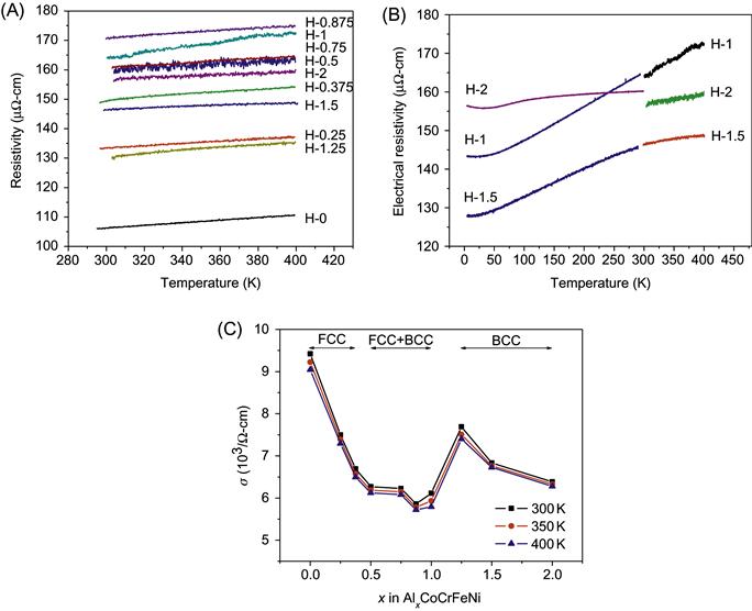
Figure 9.2 shows the electrical resistivity as a function of temperature and Al content (Chou et al., 2009). The electrical resistivity of each alloy is approximately a linear function of temperature with a small positive slope in the range of 298–400 K. At temperatures near absolute zero, the resistivity levels are generally high as compared to that (1–100 µΩ-cm) of conventional alloys. The high-level of electrical resistivity can be attributed to the severe lattice distortion and thus intense electron scattering in these alloys. Furthermore, the thermal vibration effect causing electron scattering becomes relatively smaller as compared with severe-lattice-distortion effect. This makes the alloy to have a low temperature coefficient of resistivity (TCR). This low TCR tendency might be further used as a base to develop new HEAs with even lower TCR. Potential applications in resistors are expected. The variation in electrical conductivity of AlxCoCrFeNi alloy is in three stages and can be related to the constituent phases present in each stage: single-FCC in 0≤x≤0.375, single-BCC in 1.25≤x≤2, and duplex FCC–BCC in 0.5≤x≤1. The electrical conductivity decreases with increasing x in single-phase regions and has a lower level in the duplex phase region. This could be explained based on the fact that larger amount of Al causes more severe lattice distortion and electron scattering, and also the interface between FCC and BCC phase increases electron scattering. Moreover, BCC phase has a higher conductivity than FCC phase.
9.4 Thermal Properties
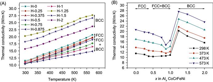
Figure 9.3 shows the thermal conductivity, κ, of HEAs as a function of temperature and Al content (Chou et al., 2009). It is seen that the thermal conductivity increases with temperature, contrary to that of pure metals. For pure metals, the collision frequency of electrons with phonons of the lattice increases with temperature and results in a shorter mean free path and thus a decreased κ. In the present alloys, lattice distortion effect that makes a lower temperature sensitivity of phonon concentration as well as thermal expansion effect that causes larger lattice spacings increase the mean free path of electrons and thus κ with temperature. Figure 9.3B shows κ as a function of x. It can be seen that κ decreases with x in each single-phase region but BCC phase has a higher κ level than FCC phase. The level of κ of alloys with x≤1 is only around 10–12 W/mK, which is very low compared with conventional alloys. This is very encouraging for those applications requiring low thermal conductivity. In addition, κ in the FCC+BCC duplex region is at the lowest level for each temperature. This trend is similar to that for electrical conductivity in Figure 9.2C. The explanation for this similarity could be based on the fact that κ has two contributions: κ=κe+κph where κe is from electron conduction and κph from phonon conduction. This is because κe is proportional to electrical conductivity and thus more sensitive to lattice distortion than phonon conductivity. On the other hand, one more reason for higher κ level of BCC structure is explained on the basis of phonon velocity. That is, higher Young’s modulus, E, of the BCC structure gives a higher phonon velocity, vph=(E/ρ)1/2, and thus a greater phonon contribution to κ (Chou et al., 2009).
9.5 Magnetic Properties
Fe, Ni, and Co are the main elements that contribute to ferromagnetism in an alloy. Suitable selection and amount of these elements and addition of other elements to HEAs could produce ferromagnetism and other magnetic properties.
Ma and Zhang (2012) reported that AlCoCrFeNbxNi (x=0, 0.1, 0.25, 0.5, and 0.75) alloys show ferromagnetic properties. With the increase in Nb content, saturation magnetizations and residual magnetizations decreased. The residual magnetization (Mr) reaches a maximum for AlCoCrFeNb0.1Ni alloy, which is 6.106 emu/g. AlCoCrCuFeNi alloy is reported to possess high saturation magnetization and undergoes a ferromagnetic transition in both as-cast and annealed (2 h at 1000°C) conditions. The values of saturation magnetization (Ms) were observed to be 38.178 and 16.082 emu/g, respectively (Zhang et al., 2010b). Lucas et al. (2011) investigated the magnetic behavior of stoichiometric FeNi, CoCrFeNi, CoCrFeNiPd, CoCrNiFePd2, Al2CoCrFeNi, and AlCoCrCuFeNi alloys. They found that these HEAs based on CoCrFeNi have low saturation magnetization and Curie temperature as compared with Fe and FeNi, and become poor candidates for soft magnetic applications at high temperatures. They attributed this phenomenon to the alloying with antiferromagnetic Cr as reflected by the fact that CoCrFeNi was paramagnetic at room temperature. However, alloying with Pd could increase the magnetic moment and Curie temperature in the FCC phase. They pointed out that the control of the Curie temperature with Pd additions may make these alloys useful for magnetic refrigeration applications near room temperature.
Lucas et al. (2013) also studied the effect of Cr concentration, cold rolling, and subsequent heat treatments on the magnetic properties of CoCrxFeNi alloys with x=0.5–1.15. CoCrFeNi HEA has a ferromagnetic Curie temperature of 130 K. When Cr content is reduced, an increase in Curie temperature occured. When CoCrFeNi alloy is cold rolled, the magnetic entropy change for a change in applied field of 2T is ΔSm=−0.35 J/kg K. Cold rolling results in a broadening of ΔSm vs. temperature curve. A heat treatment after cold rolling at 1073 K sharpens the magnetic entropy curve. It is found that upon heating (after cold rolling) there is a reentrant magnetic moment near 730 K. This feature is much less pronounced in the as-cast samples (without cold rolling) and in the Cr-rich samples, and is no longer observed after annealing at 1073 K. This reentrant magnetic moment upon heating is argued to be due to changes in short range order or the coalescence of vacancies forming stacking faults (Lucas et al., 2013).
9.6 Hydrogen Storage Properties
Hydrogen is widely considered a renewable and sustainable solution for reducing the consumption of fossil fuels. Metal hydrides have received particular attention for their excellent hydrogen storage properties. Several HEA systems have been investigated for their hydrogen storage properties.
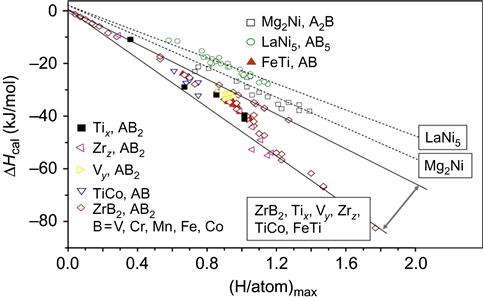
Kao et al. (2010) have used pressure-composition-isotherms (PCIs) to demonstrate that CoFeMnTixVZr, CoFeMnTiVyZr, and CoFeMnTiVZrz can absorb and desorb hydrogen for compositions of 0.5≤x≤2.5, 0.4≤y≤3.0, and 0.4≤z≤3.0. Because of the high entropy effect in the alloy system, each HEA is a multicomponent solid solution with a single C14 Laves phase structure before and after PCI test. The lattice expands when hydrides form. Maximum hydrogen storage capacity (H/M)max could be up to 1.8 wt% at room temperature for CoFeMnTi2VZr alloy. This study also elucidated the effects of the chemical composition on the properties of hydrogen storage in terms of lattice constant, element segregation, and hydride formation enthalpies. The factor that determines the maximum hydrogen storage capacity is the affinity between the alloying elements and hydrogen. In CoFeMnTixVZr and CoFeMnTiVZrz, Ti and Zr additions promote hydrogen absorption. The decrease in (H/M)max in alloys Ti2.5 and Zr3.0 can be attributed to the strong segregation of Ti and Zr in the cast structure. Following hydrogen desorption, a large amount of hydrogen is retained in Zrz alloys due to the strong bonding between Zr and H. By calculating the average formation enthalpy of hydride, they show that (H/atom)max is a linear function of ΔHcal in A2B and AB5 alloy systems as shown in Figure 9.4. Although it is nonlinear with Tix, Vy, Zrz, AB, and AB2, (H/atom)max is strongly related to ΔHcal for Tix, Vy, and Zrz. From this study, it is observed that multicomponent HEAs with C14 Laves phase structure can be obtained by varying Ti, V, and Zr contents with good hydrogen storage potential.
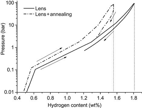
Kunce et al. (2013) prepared ZrTiVCrFeNi HEA by LENS technique. Pressure-composition-temperature (PCT) isotherms were measured up to 100 bar of hydrogen at 50°C following activation of the alloy by annealing at 500°C for 2 h under vacuum, as shown in Figure 9.5. The maximum hydrogen adsorption capacity was 1.81 wt% after synthesis and 1.56 wt% after annealing. It is found that the equilibrium pressure of hydrogen desorption was too low for a complete desorption reaction, resulting in the presence of a C14 hydride phase in the alloy after PCT tests. This indicates that a thorough understanding of the structural and accompanying hydrogen storage property changes is of fundamental importance for future development of HEAs as potential materials for hydrogen storage (Kunce et al., 2013).
9.7 Irradiation Resistance
It is known that high energy particle irradiation on solids produces atomic displacements and thermal spikes. The high atomic-level stresses in HEAs facilitate amorphization upon particle irradiation, followed by local melting and recrystallization due to thermal spikes. It is speculated that this process will leave much less defects in HEAs than in conventional alloys. For this reason, they may be excellent candidates for some nuclear applications. Initial results of computer simulation on model binary alloys and an electron microscopy study on Hf![]() Nb
Nb![]() Zr alloys, which demonstrate extremely high irradiation resistance of these alloys against electron damage to support this speculation, were reported by Egami et al. (2013). Simulations on Hf
Zr alloys, which demonstrate extremely high irradiation resistance of these alloys against electron damage to support this speculation, were reported by Egami et al. (2013). Simulations on Hf![]() Nb
Nb![]() Zr alloys lead to a conclusion that HEAs with the atomic-level volume strain close to 0.1 are self-healing and highly irradiation resistant.
Zr alloys lead to a conclusion that HEAs with the atomic-level volume strain close to 0.1 are self-healing and highly irradiation resistant.
9.8 Catalytic Properties
Nanoparticles of PtxFe(100−x)/5Co(100−x)/5Ni(100−x)/5Cu(100−x)/5Ag(100−x)/5 (x=22, 29, 52, 56) prepared by the sputter depositions on pretreated carbon clothes were investigated for their electrocatalytic ability for methanol oxidation (Tsai et al., 2009a). Cyclic voltammetry of the deposited samples demonstrated enhancements in the current response with increasing Pt content and deposition time. Pt52Fe11Co10Ni11Cu10Ag8 alloy exhibited the highest mass activity of 462–504 mA/mg. Identical process was conducted to fabricate electrodes with sputtered Pt and Pt43Ru57. In comparison, the Pt52Fe11Co10Ni11Cu10Ag8 showed moderate improvements over that of Pt but was still outperformed by the Pt43Ru57.