Intermetallics, Interstitial Compounds and Metallic Glasses in High-Entropy Alloys
While a number of equiatomic and nonequiatomic high-entropy alloys (HEAs) have shown a single solid solution, in a number of them various intermediate phases with the structure of intermetallic compounds such as B2, L12, sigma phase, and Laves phase are shown to occur. This has been attributed by many researchers to the competition among mixing entropy, mixing enthalpy, and atomic size difference between the constituent elements in these alloys. There are reports on high-entropy nitride and carbide formation as thin films on various substrates. These nitrides and carbides have the structure of interstitial compounds. There have been cases where HEA compositions have shown the formation of metallic glasses. Some of these alloys are equiatomic in nature, while some of them can be treated as pseudo-binary or pseudo-ternary with equiatomic substitution of similar elements. This chapter gives an account of intermetallic phases, interstitial alloys, and amorphous phases observed in HEAs.
Keywords
Intermetallic compounds; interstitial compounds; Hagg phase; sigma phase; Laves phase; metallic glasses
7.1 Introduction
Research in the field of HEAs for the past one decade has demonstrated that configurational entropy alone is not sufficient to explain the formation of simple random solid solutions in cases where the atomic size differences between atoms are large or when there is a strong attraction between certain elements in the multicomponent alloy. In such cases, various intermetallic phases (or intermediate phases) and under some processing conditions even amorphous phases have been observed. Among the intermetallic phases, the crystal structures most commonly observed are B2, sigma (σ) phase, and Laves phases. Often some of these phases are observed together with random (or disordered) solid solutions and are thought to be due to precipitation from the solid solutions in HEAs during slow cooling or thermal annealing of these alloys. There have been reports on high-entropy nitride and carbide thin films deposited on substrates when the sputtering of HEA targets was subjected to nitrogen and carbon containing atmosphere. They are in fact solid solutions with the structures of interstitial compounds of Hagg phase type. This chapter deals with the various compound structure and amorphous phases formed in HEAs. Nevertheless, it can be said that high-configurational entropy does play a significant role in phase evolution in HEAs, and the number of phases observed in these alloys is significantly less than the maximum number of phases predicted by Gibbs phase rule.
7.2 Intermetallic Compounds
7.2.1 B2 Phase
The B2 phase is an ordered structure based on BCC (Pearson symbol of cP2), wherein the body-centered position is occupied by one type of atom and the body corners are occupied by atoms of another kind. The most common compounds that have this structure are CsCl, CuZn, and NiAl.
The B2 phase has been observed either as a major or as a minor phase in a large number of HEAs. In some cases, it has been observed to precipitate during heat treatment of these alloys from a BCC phase. In almost all the cases where the B2 phase has been observed, the alloys contained 3d transition elements such as Ti, Cr, Mn, Fe, Co, Ni, and Cu along with Al. Among these 3d transition elements, Al has strong affinity to form B2 phase with Fe, Co, and Ni. A careful observation of the constituents of alloys that showed B2 phase indicates that all have either one of these three elements (Fe, Co, and Ni) along with Al. Not even one alloy has been reported so far in HEA literature that has shown B2 phase without the presence of the above combination of these elements. Thus, the B2 phase that is observed in these alloys can be attributed to the interaction of Al with one of the three elements, while the other elements which also have strong bonding with Al dissolve into the B2 phase mainly due to mixing entropy effect. However, due to the presence of a large number of elements, the order parameter is expected to be low and in a number of cases, the intensity of the superlattice reflections is extremely low, making the researchers to assume the phase to be a BCC solid solution (A2 structure), instead of treating it as an ordered B2 structure.
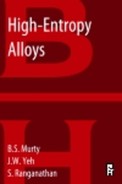
Alloys containing Cu in addition to B2 phase forming elements have shown Cu-rich FCC phase in their microstructure (Zhang et al., 2010b; Hsu et al., 2007). Studies on Al0.5CoCrCuFeNiTix alloy with different x values (Chen et al., 2006b) indicated that at x=0.4, two BCC phases (β1 and β2) form, out of which β1 becomes ordered. Between x=0.8 and 1.2, CoCr-like phase is formed, while Ti2Ni precipitates when x is in the range of 1.22 in this alloy. The microstructure of the alloy is also affected by the amount of Ti present. Higher Ti content causes Cu to segregate more in ID region because of its more negative enthalpy of mixing with other elements and consequently the area of fraction of ID also increases. The precipitates present in ID region are needle like when Ti content is low while they appear as nanoparticles at higher Ti content (Figure 7.1).
Interestingly, there are differences in phase formation for the same composition in different reports. For example, AlCoCrCuNi prepared by arc melting and casting showed the B2 phase as a major phase along with an FCC phase as a minor phase (Hsu et al., 2007). In contrast, the same alloy prepared by the same technique by Munitz et al. (2013) showed a BCC phase as a major phase and B2 as a minor phase. In AlCoCrFeNi alloy, a single-phase B2 was observed in many cases (arc melting by Wang et al., 2008; Bridgeman solidification by Zhang et al., 2012b; suction casting by Qiao et al., 2011 and Hsu et al., 2013a; and electro-spark deposition by Li et al., 2013c). Thus, the phase formation in HEAs appears to be quite sensitive to the processing conditions. Table A2.1 of Appendix 2 lists the HEAs in which a B2 phase has been observed, either as a single phase or together with some other phase.
7.2.2 L12 Phase
The L12 phase is an ordered structure based on FCC (Pearson symbol of cP4), wherein the face-centered positions are occupied by one type of atom and the body corners are occupied by another kind of atom. The most common compounds that have this structure are AuCu3 and Ni3Al.
A small number of HEAs have shown the presence of L12 phase (Table A2.2 of Appendix 2). All these alloys containing both Al and Ni possess FCC phase and also show L12 phase in the matrix (Li et al., 2008b; Hemphill et al., 2012; Manzoni et al., 2013a). As mentioned above, Al content should not be high, otherwise BCC and B2 phases would form. In such HEAs, the L12 phase is the multicomponent version (including Ni, Co, Fe, Ti, etc.) of γ′ Ni3Al that is usually observed in Ni-base superalloys.
7.2.3 Sigma Phase
The σ phase is usually observed in Cr-containing steels and has a typical composition of equiatomic FeCr with a tetragonal structure. The σ phase has also been observed with equiatomic CoCr or FeMo in binary Co–Cr and Fe–Mo alloys.
A large number of HEAs containing Fe and/or Co together with higher amounts of Cr and/or Mo have shown the formation of σ phase at various stages of their processing. In HEAs, the σ phase is also a multicomponent solid solution. The formation of σ phase is an indication that different types of solid solutions in HEAs could form depending on the interaction and atomic size difference between elements and not just the configurational entropy alone. The σ phase is in fact a topologically close-packed phase in which components with larger atomic size occupy one specific set of lattice sites while smaller atoms occupy another set so as to get a higher number of bonding to lower its overall free energy, although their interactions (or enthalpy of mixing) between components are small. Table A2.3 of Appendix 2 gives the HEAs in which the σ phase has been observed.
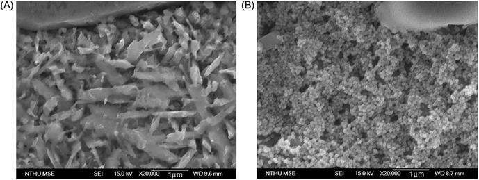
Hsu et al. (2010b) studied AlCoxCrFeMo0.5Ni alloys with different cobalt content. For x=0.5, 1.0, and 1.5, ordered BCC and σ phases are present, whereas a FCC phase appears when x=2 indicating the FCC stabilizing nature of cobalt. The σ phase is believed to be a solution of CoCr, FeCr, FeMo, and NiMo phases. The microstructure of the alloys consists of DR, ID, and eutectic structure at x=0.5; DR and ID structure (without eutectic structure) at x=1 and 1.5; and polycrystalline single phase structure at x=2 (Figure 7.2). In this figure, modulated structures are revealed in (Al,Ni)-rich BCC DR and (Cr,Mo)-rich BCC ID regions at x=1 and 1.5. They form by phase decomposition from BCC phase into σ phase and ordered BCC (B2) phase during the cooling stage. For x=2, σ phase forms along grain boundaries, and σ phase stringers with B2+FCC mixture between the stringers are observed in grain interiors.
Addition of molybdenum tends to stabilize the formation of a BCC structure and/or appearance of a σ phase. XRD studies of Co1.5CrFeNi1.5Ti0.5Mox alloys showed that σ phase begins to form as Mo content reaches x=0.5 (Chou et al., 2010b). Formation of σ phase has also been reported in CoCrFeNiMox alloys with increasing Mo content (Shun et al., 2012a). Increasing Mo content has also been shown to transform the cast structure to a eutectic structure (Zhu et al., 2010a). When added to AlCrFeNi alloys, Mo dissolves preferentially in the (Fe,Cr)-rich BCC phase while the other BCC phase, based on Al–Ni is lean in Mo (Dong et al., 2013a). Increase in Mo content transforms the eutectic microstructure to hypo/hyper eutectic structure. This preference is probably due to higher driving force for the formation of a stable σ phase of FeCrMo type.
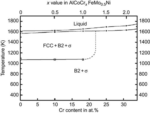
Cr is an important constituent in HEAs, and as already discussed in the context of equiatomic alloys, Cr stabilizes the BCC structure and promotes formation of the σ phase particularly in presence of Fe, Co, and Ni. Hsu et al. (2011) plotted the phase diagram to a first approximation of AlCoCrxFeMo0.5Ni alloy (Figure 7.3) for various chromium contents to first approximations based on experimental results of DTA, high-temperature XRD, and microscopic analysis. It indicates that a σ phase is likely to form for all chromium contents along with a B2 phase. At higher temperatures, a FCC phase evolves when the Cr content is less than 20 at.%. It may be noted that the σ phase is also present when x=0; which shows that Cr solely is not responsible for the formation of the σ phase although it certainly accelerates the process. The σ phase can therefore be thought of as a solid solution of various binary σ phases possible like Co–Cr, Fe–Cr, Ni–Mo, Fe–Cr–Mo, Cr–Mo–Ni, and Co–Fe–Mo (ASM Handbook, 1992). Confirmation of such a diagram may prove immensely helpful in establishing the design criteria for various HEAs.
Chen et al. (2006a) discussed the effect of vanadium on FCC Al0.5CoCrCuFeNi alloy. The crystal structures of Al0.5CoCrCuFeNiVx alloy system are essentially FCC, BCC, and σ phase, in which the σ phase forms from x=0.6 to 1.0. It is seen that the BCC phase begins to appear at x=0.4 and its amount increases with increase in V content up to x=2.0. The σ phase is a multicomponent solid solution having the same structure as equiatomic NiCoCr phase but this σ phase contains a higher amount of vanadium than other phases in the matrix.
Formation of σ phase is likely to occur when elements like Cr and V are present along with Ni and Co. Chen et al. (2008) reported that σ phase is observed when AlCrCoMoNi layer is produced by TIG cladding. This σ phase has a simple tetragonal structure with lattice parameters of a=0.875 and c=0.451 nm. Chen et al. (2009a) synthesized AlCrCoFeMoNiSi alloy with various Si contents. The Si-free alloy showed the presence of σ phase. With addition of Si, the σ phase disappeared and a new phase FeMoSi evolved which has an hcp structure with lattice parameters a=0.765 and c=0.477 nm.
7.2.4 Laves Phase
Laves phases are intermetallic compounds that have a stoichiometry of AB2 and are formed when the atomic size ratio is between 1.05 and 1.67. There are three classes of Laves phases, namely, cubic MgCu2 (C15), hexagonal MgZn2 (C14), and hexagonal MgNi2 (C36). In these compounds, the A atoms take up ordered positions as in diamond, hexagonal diamond or related structure while the B atoms take up tetrahedral positions around A atoms. In case the atomic size ratio of A and B atoms is around 1.225, they form topologically tetrahedral close-packed structures with overall packing density of 0.71.
Many HEAs have also shown the formation of Laves phase either as a major phase or a minor phase. Table A2.4 of Appendix 2 lists the HEAs in which Laves phase has been observed. Shun et al. (2012b) have reported the formation of (Ti,Co)-rich Laves phase in CoCrFeNiTi0.5 alloy prepared by arc melting. Mishra et al. (2012) have also observed Ti2Co-type Laves phase in CoCuFeNiTi alloys when Ti/Cu ratio is larger than 9/11. Senkov et al. (2013c) observed Cr-rich Laves phase along with two BCC phases in the arc-melted CrMo0.5NbTa0.5TiZr alloy. In all the above alloys, the formation of Laves phase can be attributed to the presence of Ti along with other transition elements. Dong et al. (2013b) have observed a Laves phase along with FCC and BCC phases when x=0.8 in AlxCoCrFeNiTi0.5. Interestingly, the alloy without Al showed only a FCC phase. Qiu et al. (2014) have observed Laves phase in laser cladded Al2CoCrCuFeNiTix with x=0.5 and 1.5. Ma and Zhang (2012) observed Laves phase in a Nb-containing HEA. They observed (Co,Cr)Nb-type Laves phase along with a BCC phase in AlCoCrFeNiNbx alloys when x=0.25–0.75. At lower Nb content, only a BCC phase has been observed.
In the absence of copper, Al0.5CoCrFeNiTix alloys (Zhou et al., 2007b) show that only a single-phase solid solution is present up to x=1.0 and phase separation occurs only at higher Ti contents (x=1.5) with the evolution of a Laves phase of Fe2Ti type. When Al is not present in the alloy, Ti is shown to precipitate out to form complex phases. CoCrFeNiTix alloy which has a single-phase FCC structure when x=0 exhibits presence of R and σ phases when x=0.3 and Laves phase at x=0.5 (Shun et al., 2012b). The R phase is rich in Ni and Ti corresponding to (Ni,Co,Fe)2(Ti,Cr), the σ phase is (Fe,Cr)-rich and of (Cr,Ti)(Fe,Co,Ni)-type, and the Laves phase corresponds to (Co,Fe,Ni,Cr)2Ti and is rich in Ti and Co.
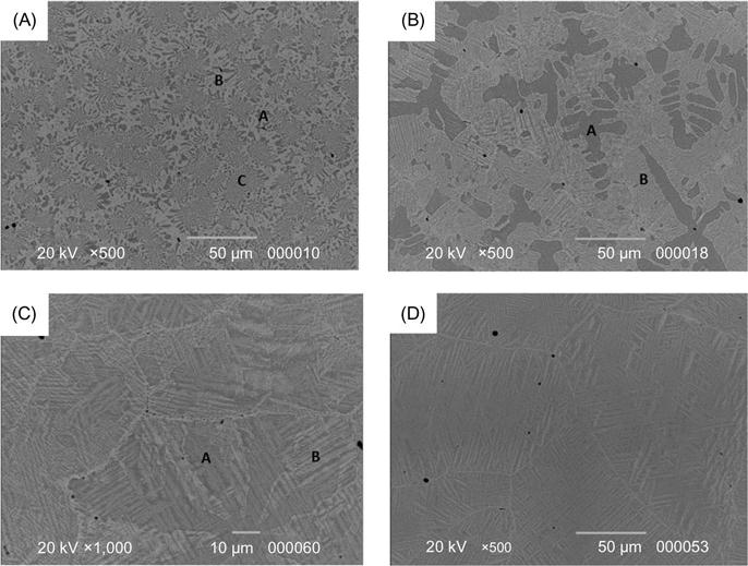
Kunce et al. (2013) reported the synthesis of CrFeNiTiVZr HEA from elemental powders in an equiatomic ratio using LENS technique. The chemical homogeneity of the alloy was improved through annealing at 1000°C for 24 h. The resulting alloy exhibited a two-phase structure with a dominant C14 Laves phase and a minor α-Ti solid solution. Cheng et al. (2014) developed CoCrCuFeNiNb HEA coating by plasma transferred arc cladding. In the absence of Nb, the alloy showed a single-phase FCC structure in the coating, while the Nb-containing coating showed a (CoCr)Nb-type Laves phase along with a FCC phase (Figure 7.4). The Nb-containing coating showed significant improvement in hardness, Young’s modulus, wear resistance, and corrosion resistance in comparison to the coating without Nb.
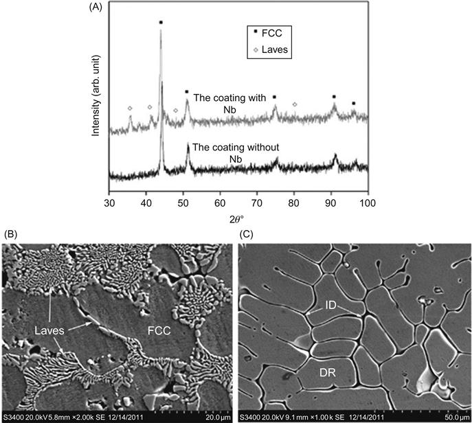
Table A2.5 of Appendix 2 lists a few HEAs, which show other intermetallic phases including quasicrystalline phase.
7.3 Interstitial Compounds (Hagg Phases)
An interstitial compound is formed when sufficiently small atoms occupy specific interstitial sites in a metal lattice. They are also called Hagg phases. For example, transition metals generally crystallize in either the hexagonal close-packed or face-centered cubic structures providing different sets of tetrahedral and octahedral sites. Their typical stoichiometric compounds are MX, M2X, MX2, M3X and M6X where M can be Zr, Ti, V, Cr, Fe, etc. and X can be H, B, C, and N.
HEA concept can be extended to create high-entropy ceramics including nitrides, carbides, oxides, and their combinations. Table A2.6 of Appendix 2 lists a few HEAs that have been used to form carbides and nitrides. New interstitial compounds with multicomponent lattice have been synthesized by reactive sputter deposition methods. In 2004, first HE nitride film was deposited from a HEA target of FeCoNiCrCuAl0.5 alloy by reactive magnetron sputtering method (Chen et al., 2004). HEA film having a FCC structure and a hardness of 4.4 GPa was obtained without the reaction with nitrogen (i.e., at 0 sccm). As nitrogen flow rate increased, nitrogen content of films increased correspondingly approaching 41 at.% at the flow rate 20 sccm. The structure became a mixture of nanocrystalline HE nitride and an amorphous phase. The hardness was also increased to 10.4 GPa mainly because the number of strong bonding of Al–N, Cr–N, and Fe–N increased.
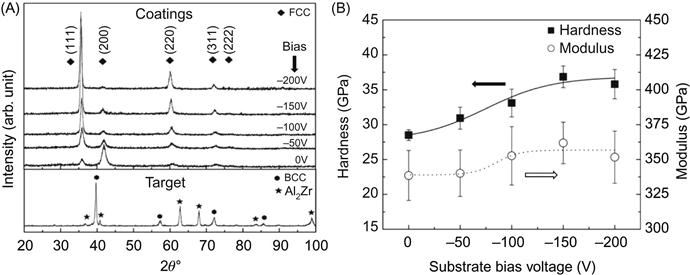
Based on this, the composition was altered to get higher film hardness by using strong nitride forming elements. Lai et al. (2006b) used the target of equiatomic HEA AlCrTaTiZr to deposit nitride films under different bias voltages in an atmosphere of Ar and N2. Figure 7.5 shows the XRD patterns of target and films. Although the constituent phases of the target are FCC and a multicomponent phase with the structure of Al2Zr compound, all the coatings form NaCl-type FCC structure in which N atoms occupy the Cl− sites and target elements occupy the Na+ sites. As a result, the HE nitride obtained was a simple solid solution of binary nitrides based on target elements. The composition can be approximated to the stoichiometric formula (AlCrTaTiCr)50N50 where the five metal elements are nearly in equiatomic ratio. Hardness and Young’s modulus of the coatings increase with increasing bias voltage due to densification, grain refining, and increased residual compressive stress. It is apparent that the hardness level of such HE nitride is much larger than that of HE nitride film deposited from FeCoNiCrCuAl0.5. This is mainly because all Al, Cr, Ta, Ti, and Zr can form strong bond with nitrogen.
After this research, more HE nitrides have been developed toward higher hardness, softening resistance, and oxidation resistance in order to prolong the lifetime of cutting tools and dies. Similarly, hard HE carbide films have been researched with reactive sputtering methods by co-sputtering with graphite target or using Ar+CH4 gas flow. Besides the amorphous structure and smaller hardness of (AlBCrSiTi)N, other HE nitrides and carbides have NaCl-type FCC structure and much higher hardness and Young’s modulus. It has been demonstrated that the FCC structure is thermally stable even after 1100°C annealing for 5 h (Tsai et al., 2012; Huang and Yeh, 2010). This suggests that such HE films would have stronger high-entropy effect than the enthalpy effect due to the differences in chemical bonding, atomic size, and crystal structure, and thus avoid phase separation into individual binary or ternary nitrides.
The first high-entropy bulk carbide (CrNbTiVW)50C50 with the transition elements in equiatomic ratio was synthesized through MA and solid-state sintering and reported in 2012 (Yeh et al., 2012). The sintered carbide is a thermally stable NaCl-type FCC solid solution of five binary carbides. Nano-powder prepared by ball milling is the key factor to realize the successful pressureless sintering at a low temperature of 1723 K, about 0.56 of the melting point (3108 K) as predicted by the rule of mixture. The average nanohardness value of 32±3 GPa is higher than the rule-of-mixture value of 23 GPa by about 40%, indicating significant solution hardening effect.
7.4 Metallic Glasses
As discussed in Chapter 3, the field of metallic glasses is indebted to Pol Duwez and Inoue for their pioneering work in conventional and bulk metallic glasses, respectively. Most of these metallic glasses are based on one principal element (such as Zr-, Fe-, Al-, and Mg-based glasses).
Cantor (2007) has pioneered a new class of glasses by substituting elements of similar nature in equal amounts in ternary glasses. For example, in a Zr–Cu–Al glass forming system, he substituted Ti, Hf and Nb for Zr, Ni and Ag for Cu and could make glassy alloys with about eight elements. The system studied by Cantor’s group is (Ti,Zr,Nb,Hf)–(Ni,Cu,Ag)–Al. Though these alloys have as many as eight elements, they can be referred to as pseudo-binary or pseudo-ternary alloys. The configurational entropy of all these alloys is higher than 1.5R, thus qualifying them to be referred to as HEA glasses. Table A2.7 of Appendix 2 gives a list of multicomponent glassy alloys that have been formed by equiatomic substitution.
In another interesting study, Takeuchi et al. (2011) took the best glass forming composition reported so far (Pd40Ni20Cu20P20) and replaced half of Pd with Pt and obtained the first equiatomic metallic glass (Pd20Pt20Ni20Cu20P20) by melting the alloy along with a flux in vacuum sealed quartz tube followed by water quenching. However, similar to Cantor’s alloys, this alloy can also be referred to as a pseudo-binary alloy as Pt, Ni, and Cu are all similar elements to Pd and substituted for Pd in a Pd80P20 alloy. Takeuchi et al. (2013b) have also made CuNiPdTiZr equiatomic glass by melt spinning and in this case it can be considered as equiatomic substitution of Ti for Zr and Ni and Pd for Cu in Cu60Zr40 glass which is well known. Similarly, Ding and Yao (2013) took the equiatomic substitution route to form an equiatomic BeCuNiTiZr (or ZrTiCuNiBe) glassy alloy, whose composition can be referred to as (ZrTi)40(CuNi)40Be20.
The equiatomic quinary glassy compositions prepared by Gao et al. (2011) by induction melting and subsequently casting into copper mold, namely, CaMgSrYbZn and AlDyErNiTb do not appear to fit into the above equiatomic substitution category and hence can be treated as true equiatomic HEA glasses. However, it is not clear whether the glass formation in these alloys is entropy driven due to the high-configurational entropy of the alloy. In addition to the conventional processing route of melting and casting, several HEA glasses are also obtained either in the thin film form by magnetron sputtering or in the powder form by MA.
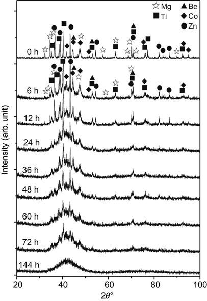
Chen et al. (2010b) reported amorphization in BeCoMgTi and BeCoMgTiZn alloys after ball milling for 144 h. This is indicated in Figure 7.6. The amorphization is of Type 2 according to classification of Weeber and Bakker (1988) since no crystalline solid solutions and compounds were formed before full amorphization in BeCoMgTi and BeCoMgTiZn alloys during MA. The inhibition of intermetallic compounds before amorphization is due to chemical compatibility among the constituent elements in conjunction with high-entropy effect and deformation effect which enhance the mutual solubility. Direct formation of the amorphous solid solution phase instead of the crystalline one can be attributed to the large range of atomic size. Table A2.7 of Appendix 2 gives various equiatomic and nonequiatomic HEAs that form glassy structures.