
CHAPTER 10
HA Security Systems
SECURITY SYSTEMS ARE CURRENTLY a hot topic in the HA field. There are literally dozens of such systems on display at major home improvement stores and “big box” electronics outlets. I could not in good conscience write an HA book without discussing this topic. In order to properly discuss home security, I would first like to discuss the concept of risk because it has a big impact on the type of security system required for a specific situation.
Risk
Most readers have heard and used the word risk many times. Most probably have not thought too much about what it actually means and how it may be used in analyzing a particular condition. The online Merriam-Webster Dictionary definition of risk is
1: possibility of loss or injury: peril
Parts List
2: someone or something that creates or suggests a hazard
3a: the chance of loss or the perils to the subject matter of an insurance contract; also: the degree of probability of such loss
b: a person or thing that is a specified hazard to an insurer
c: an insurance hazard from a specified cause or source: war risk
4: the chance that an investment (such as a stock or commodity) will lose value
I prefer a simpler definition, which is actually contained in the same dictionary definition but is rephrased to highlight an important consequence:
Risk is the probability of a hazard happening.
This simple definition raises the question, what constitutes a hazard? Common sense dictates that a hazard is any unwanted event, which could be as minor as misplacing your car keys or as catastrophic as having your home burn down. Common security hazards likely encompass some of the following:
![]() Smoke/fire
Smoke/fire
![]() Water/flood damage
Water/flood damage
![]() Carbon monoxide (CO)
Carbon monoxide (CO)
![]() Burglars
Burglars
![]() Home invasion
Home invasion
![]() Loss of power
Loss of power
![]() Pet confinement
Pet confinement
![]() Privacy
Privacy
There are likely others that may be of concern, but let’s stick with this short list. Each of the listed hazards typically has a probability associated with it. This probability is the chance that a hazard will happen. You will likely not know this value, which ranges from 0 to 1.0. A 0 value means that there is absolutely no chance that a particular hazard will occur, whereas a 1.0 value means that it is 100 percent certain that a hazard will happen. For example, in the area where I live, it is common to have a loss of power occasionally during or after a severe storm passes through. Some probability values can only be determined by contacting appropriate local authorities. The local police chief or sheriff will likely have good statistics on the number of home burglaries and/or home invasions. Likewise, the local fire chief can provide good data on the number of home fires that have happened recently in your city or town.
Identifying potential hazards should always be the first step in creating an optimal security system tailored toward a specific home or business. The next step is collecting or otherwise assigning a probability to the identified hazards. Sometimes you must assign a value based solely on a “gut” feeling for the likelihood of a hazard happening. In any case, the next step is to whittle down the list and eliminate hazards that have a low probability of happening.
The next step in the process is to evaluate the cost versus benefit of mitigating the risk associated with all the hazards remaining on the list. Sometimes this is a rather easy task when considering risk versus cost. For example, mitigating the risk associated with smoke, fire, and CO detection in a home is just the purchase of a sufficient number of appropriate detectors and installing them in the recommended stations throughout the home. This risk mitigation is fairly inexpensive and, considering the hazard involved, an absolute necessity. In fact, most cities and towns in the United States at present require by government regulation that smoke detectors be installed in all new construction, whether it is residential or commercial.
Evaluating how much to spend on mitigating burglary risk is more problematic. It really depends on the crime prevalence in your community. If there have been many burglaries in your neighborhood, then the question becomes not if, but when. In this case, you should invest in a highly capable security system that will make your property less of a tempting target than other local properties. By contrast, if there have been no or extremely few burglaries in your area, then a minimal, inexpensive system likely would be appropriate. Notice that I did not say that no system was required because criminals always seem to be in ample supply and will eventually strike.
This discussion is simply a prologue to my first demonstration of a relatively simple security system that uses a single PIR sensor first described in Chapter 9.
PIR Security System
This system will implement a motion-detection system that can be placed high up in a room corner where it can cover the entire space. The remote PIR sensor is battery operated to facilitate easy placement and provide great flexibility to the user so that a room may be properly covered. I started this project with a list of requirements to clearly delineate what was needed and to ensure that the system met the specific objectives required for implementing the room security.
Security System Requirements
The following is a list of the minimal requirements necessary to meet the goals of the security system:
![]() PIR motion detector
PIR motion detector
![]() Remote sensor, battery operated
Remote sensor, battery operated
![]() Wireless data transmission capability to a main RasPi controller
Wireless data transmission capability to a main RasPi controller
![]() Voice assistant activation
Voice assistant activation
![]() Wireless alert/alarm transmission from the RasPi controller to the voice assistant
Wireless alert/alarm transmission from the RasPi controller to the voice assistant
These requirements can be addressed in a variety of ways. I decided to break up the project into a series of subsystems to ease the overall design and construction.
Remote Sensor Hub
The components of the remote sensor assembly are shown in the block diagram in Figure 10-1. Note that I used two Arduino Uno Rev 3 boards as a controller for this the wireless data subsystem. An Uno controller is in direct wireless connection with the main RasPi controller using an XBee Shield, which, in turn, interfaces with an XBee RF module that implements the Zigbee data communications protocol. I discuss the XBee Shield, the XBee Module, and the Zigbee protocol in the next section.
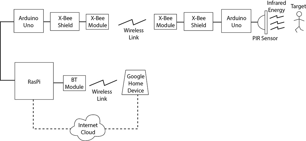
Figure 10-1 Remote sensor hub block diagram.
The remote hub Uno controller will send an alert/alarm signal to the RasPi when it receives a signal from the PIR sensor on detecting motion within the room. The complete remote sensor assembly is power by a 6-V battery pack.
XBee and Zigbee Technologies
I selected XBee transceivers to implement the RF link because they are small, lightweight, inexpensive, and totally compatible with Uno boards. They also can transmit programmed digital data packets, unlike the RF transceivers discussed in Chapter 2, which only transmit several fixed and unchangeable digital data values. This additional flexibility is important in order to be able to transmit specific sensor data to support data-generator sensors. A data-generator sensor might include one that passes environmental data such as temperature and/or humidity.
XBee is the brand name for a series of digital RF transceivers manufactured by Digi International. Figure 10-2 shows one of the XBee Pro S1 transceivers that I used. There are two rows of 10 pins on each side of the module. These pins are spaced 2 mm apart, which is incompatible with the standard 0.1-inch spacing used on solderless breadboards. This means that a special connector socket must be used with the XBee Module to interconnect it with the Uno. This special socket is part of the XBee Arduino Shield, which is shown in Figure 10-3.
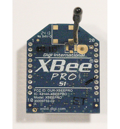
Figure 10-2 XBee Pro S1 transceiver.
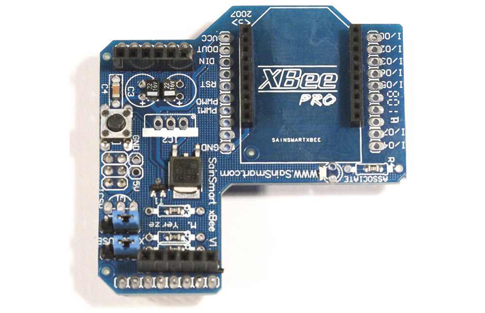
Figure 10-3 XBee Arduino Shield.
This shield can be purchased from sainsmart.com and contains all the functionality needed to effectively interface an Arduino board such as the Uno with an XBee Module. The shield and accompanying software make it very easy to create a useful RF communications link with very little effort.
The following sidebar examines the XBee hardware to show how this clever design makes wireless transmission so easy. Feel free to skip the sidebar if you are not particularly interested in learning about the XBee technology.
XBee Hardware
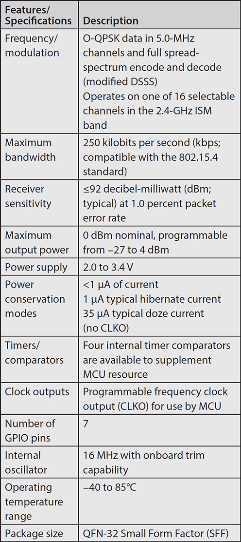
All the electronics in the XBee hardware, except for the antenna, are contained in a slim metal case located on the bottom of the module, as can be seen in Figure 10-4. If you look closely at the figure, you should see the bottom of the antenna wire, which is located near the top left corner of the case. While Digi International is not too forthcoming regarding what makes up the electronic contents of the case, I did determine that the earlier versions of the XBee Pro transceivers used the Freescale Model MC13192 RF transceiver. This chip is a hybrid type, meaning that it is made up of both analog and digital components. The analog components make up the RF transmit-and-receive circuits, whereas the digital components implement all the other chip functions. It is a complex chip, which is the reason why the XBee Module is so versatile and able to automatically perform a remarkable number of networking functions. Table 10-1 shows a select number of features and specifications for the MC13192 chip.
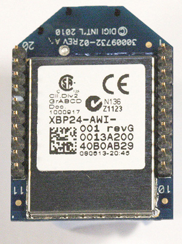
Figure 10-4 XBee electronics case.
Table 10-1 Freescale MC13192 Features and Specifications
The XBee Module implements a full network protocol suite, but from a hardware perspective, this means that there must also be a microprocessor present in the electronics case. From my research, I cannot determine which type of microprocessor it is, but I am willing to make an educated guess that it is a Freescale chip based on the reasonable assumption that the MC13192 would be designed to be highly compatible with the company’s own line of microprocessors. One other factor supporting my guess is that Digi International has recently introduced a line of programmable XBee Modules named XBee Pro SB that use the 8-bit Freescale S08 microprocessor.
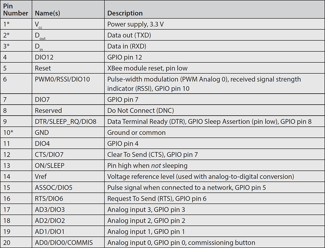
The XBee pins are detailed in a logical arrangement in Figure 10-5 for your information. All the pin and function descriptions are shown in Table 10-2. Be aware that only four of the pins are needed for this project, and they are shown with an asterisk next to the pin number.
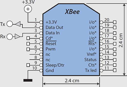
Figure 10-5 Logical XBee pin-out diagram.
Table 10-2 XBee Pin Descriptions and Functions
A considerable number of functions are available to you if needed, but this project requires only the most minimal functions for simple and reliable data transfers. Thankfully, the two XBee Modules automatically connect and establish reliable communications when power is applied to them. A red blinking LED on the XBee Shield is your indication that a communications link has been established.
I will finish this sidebar by mentioning that the XBee uses a highly capable networking protocol name Zigbee, which is also called a personal area network (PAN).
I fit the Uno board along with the XBee Shield and Module into a plastic case, as shown in Figure 10-6. The assembly is completely self-contained and is easily mounted to a wall surface using adhesive Velcro strips. I also decided to use a small solderless breadboard within the case to facilitate interconnecting all the components for the first prototype. It is always important to be able to easily reconfigure and reconnect components during initial testing to resolve any latent problems or issues. Figure 10-7 shows the electrical schematic for the complete hub assembly, which includes a PIR sensor.
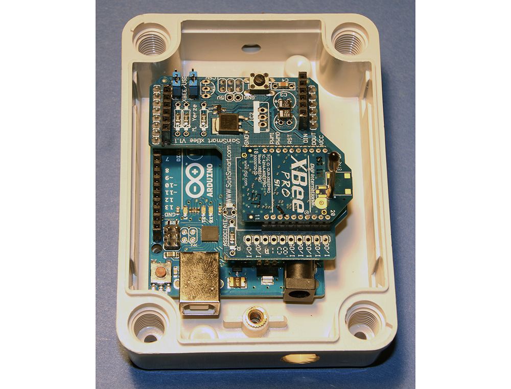
Figure 10-6 Remote sensor hub in a plastic case.
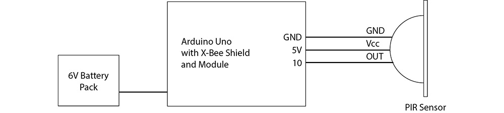
Figure 10-7 Remote sensor hub schematic.
I also connected a coaxial plug to the battery pack, which inserts into the Uno board’s coaxial power socket. I disconnect the power when not testing to conserve battery life. The Uno board with the Arduino Shield removed is shown in Figure 10-8.
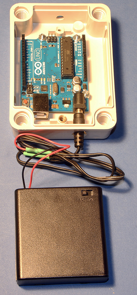
Figure 10-8 Battery pack connection to remote sensor hub assembly.
I will discuss the remote sensor assembly software after the next section concerning the main RasPi controller.
Main Controller Assembly
I used a RasPi 3, Model B, as the main controller for this project. Figure 10-9 shows the block diagram for the main controller assembly.
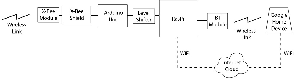
Figure 10-9 Main controller assembly block diagram.
The RasPi has an Uno board along with an XBee Shield and XBee Module, which provide two-way communication with the remote sensor hub. It also has an external Bluetooth transceiver that wirelessly connects to the voice assistant, enabling an audio stream to be sent from the RasPi to the voice assistant. The audio stream is sourced from the RasPi’s 3.5-mm audio output jack. You may be wondering why I didn’t just use the built-in Bluetooth connection hardware in the RasPi 3. The answer is that I did try it and found that the software installation was quite difficult and the actual wireless connection was just too unreliable. I decided that use of an external Bluetooth module was a much simpler and more reliable approach, and the module cost was also reasonable. Sometimes you just have to take an alternative route to proceed with a project.
The complete main controller assembly was set up on a tabletop for convenience without any attempt to package it as a complete assembly. It is powered from AC mains except for the external Bluetooth module, which has an internal rechargeable battery. However, I did plug the module’s charging micro USB cable into one of the RasPi’s USB sockets. The main controller schematic is shown in Figure 10-10.
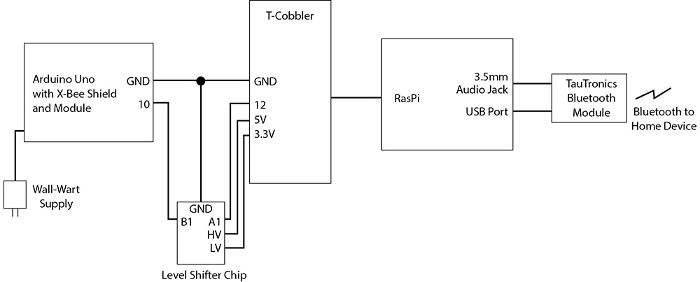
Figure 10-10 Main controller assembly schematic.
I used a solderless breadboard with a T-Cobbler interface adapter to interconnect all the components for convenience and ease of assembly. I would have housed all the components in a plastic case if I had wanted to make this system a permanent item in the house. However, a tabletop version was adequate for this prototyping stage.
The remaining system component to be discussed is the voice assistant.
Voice Assistant
I elected to use the Google Home device to act as the voice assistant for this project. I decided on this unit because I liked the idea of using Web services with the RasPi main controller so that I could easily expand the system capabilities without having to fuss with the Alexa Skills, if I elected to go that route. Feel free to use an Alexa device if you so choose, but you will need to create your own Skill software to communicate with the Alexa device. That should not be too hard, provided that you follow the guidelines I presented in Chapter 4.
The Home device applet software is detailed within the following software generation and installation sections.
Software Generation and Installation
I have chosen to parse the software sections into separate groups, where each group addresses a major system component. The first component I discuss is the RasPi’s main controller because that is the cornerstone of the complete system.
Main Controller Web Software
Creating the RasPi’s Web software is a fairly simple process as long as you keep in mind what the subsystem requirements are and how they should be implemented. The requirements for the main controller are as follows:
1. Respond to a Web request to activate the system
2. Activate the sensor by sending a signal to the remote sensor assembly
3. Respond to any alert/alarm message sent by the remote sensor assembly
4. Send a present alert/alarm to the voice assistant via Bluetooth
I will comment on each one of these requirements as I go through the Web software development details.
In the spirit of rapid software development, I decided to reuse the Web server code I created in Chapter 2. I simply extended the existing code by creating a new snippet that would respond to any applet requesting that the PIR sensor be enabled. Please review the Chapter 2 discussion regarding applets and corresponding Web services if what I just mentioned does not make sense to you.
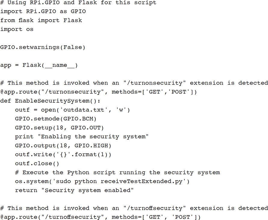
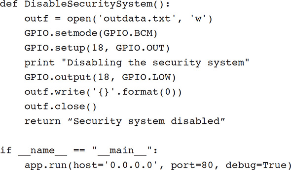
The newly extended Web server code listing, which I named securityTest.py, is as follows:
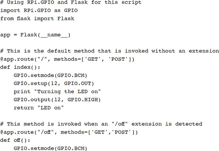
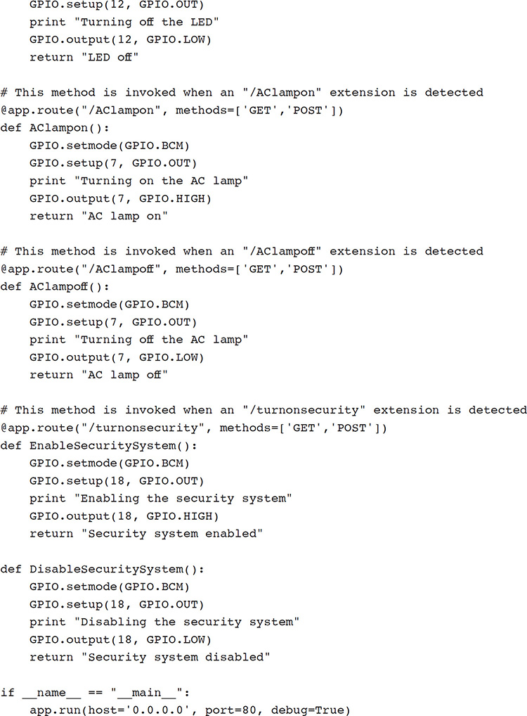
But wait, if you examined the listing, you realized it only controls GPIO pin 18 and has nothing in it that would activate the remote sensor hub. I did this on purpose because I have not yet shown you anything regarding how I implemented RF communications software and what type of data are linked between the main controller and the remote sensor hub. It is almost always a serious mistake to attempt to implement every requirement at one time. In this case, I will only light a LED connected to pin 18 as proof that the Web request is working as expected. The RF software portion will come later as I complete all the code.
The next logical step in code development is to create two applets that will request that the security system be enabled or disabled. Again, I will not repeat the clear instructions provided in Chapter 2 but simply summarize some of the information required to create the applets. One new applet is required to activate the security system and another one to disable it. I used the following example URLs for these applets:
http://mytestsite.org/turnonsecurity
http://mytestsite.org/turnoffsecurity
Please note these URLs are just examples, not real ones, so they will not work. The applets both use a POST method, which is how the desired action is directed to the appropriate method within the RasPi Web server.
The activation trigger phrases I used in the applets are
![]() “Turn on security system”
“Turn on security system”
![]() “Turn off security system”
“Turn off security system”
The two response phrases are
![]() “The security system is on”
“The security system is on”
![]() “The security system is off”
“The security system is off”
The main controller software is ready for a quick initial test prior to proceeding with adding more complexity to the system.
Initial Test I connected a LED to GPIO pin 18 in preparation to test the newly extended RasPi Web server. I then started the RasPi Web server with this command:
sudo python securityTest.py
I then spoke the next phrase to test the “Turn on security system” applet:
![]() “OK Google, turn on security system.”
“OK Google, turn on security system.”
The LED connected to pin 18 turned on after I spoke the phrase into the Home device. I also heard the phrase “The security system is on” come from the Home device, confirming that the Web request was completed. In a similar manner, the LED turned off after I spoke the phrase “OK Google, turn off the security system.” As above, I heard the phrase “The security system is off” come from the Home device, confirming that the desired Web request was completed.
These actions confirmed that the Web server and applets were functioning as desired. It was now time to expand the software to include the RF communications link with the remote sensor hub.
RF Communications Link My initial objective in implementing the wireless link was just to convey a state change whenever the PIR sensor detected motion. By far the easiest way to do this was by using GPIO pins on both the Uno controller and one RasPi GPIO pin. I was well aware that this approach runs counter to what I discussed earlier in having actual data sent, but my immediate goal was to quickly and reliably create a working RF link. The wireless link can be extended at a later time to handle real data exchanges, but for now, I just wanted to get the system up and running.
Remote Hub Hardware and Software Installation I already described the remote hub assembly in a previous section. I do have to provide a schematic showing how the PIR sensor connects to the Arduino board before describing the software that controls the whole assembly.
Remote Hub Hardware Installation Figure 10-7 showed the three-wire connection between the Uno and the PIR sensor. I mounted the PIR sensor to a small solderless breadboard, which was attached to the plastic case. The three interconnecting wires were routed through a hole on the top of the case to the Arduino board. Figure 10-11 shows the complete assembly with the PIR sensor in place.
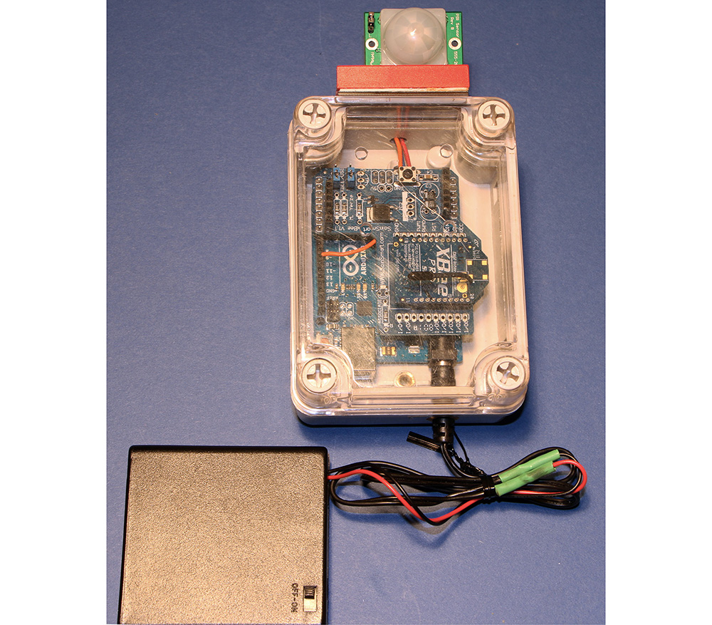
Figure 10-11 Complete remote hub with sensor.
You will be ready for the remote hub software installation once the preceding assembly steps have been completed.
Remote Hub Software Installation You will need to install the latest Arduino IDE in order to install the code described in this section. This is a free IDE download available for Windows, Mac, and Linux platforms at https://www.arduino.cc/en/Main/Software. I will not attempt to explain how to use this software because most of the readers of this book are quite likely to be very familiar with this IDE. However, a lot of information and tutorials are available on the Internet for readers who have never used an Arduino.
This next listing, which I named pirTest.ino, transmits either a 1 or a 0 to any other XBee in its vicinity. A 1 is sent whenever the PIR sensor detects an object in its field of vision; otherwise, a 0 is transmitted. The 1’s or 0’s are sent out once per second.
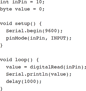
This program is written using the Processing language, which for all practical purposes is a lightweight version of C/C++. The Serial class performs all the functions necessary to automatically interface the Uno with the XBee Shield. The statement
Serial.println(value);
is all that it takes to transmit the data values using the XBee Shield.
There is no need to go through a power-on sequence with the Uno board. Any uploaded program stored in its EEPROM will automatically run when power is applied to the Uno. Likewise, the Uno is designed to shut off “gracefully” when the power is disconnected.
No other software installations are required for the remote sensor hub. The next software installation to be discussed concerns the main controller assembly.
Additional Main Controller Hardware and Software Installations I have already described most of the principal components required for the main controller assembly in a previous section. The Web software necessary to control the main controller assembly was also described and tested in previous sections. I also provided a schematic showing how the Uno with an XBee Shield attached connects to the RasPi. In addition, I described how to set up the external Bluetooth module, which creates a wireless link between the RasPi and the Home device.
Main Controller Hardware Installation Figure 10-10 showed how to connect the Uno to the RasPi. Please note that I used a level-shifter chip between the Uno and the RasPi because the Uno output level is 5 V, whereas the RasPi cannot handle any level greater than 3.3 V without likely damage. Both the 3.3- and 5-V supplies are sourced from the T-Cobbler adapter.
The Uno and XBee assembly are powered from a separate wall wart power supply. Do not attempt to power the Uno from the T-Cobbler 5-V power source. There is simply not enough current available from that source to power both the RasPi and Uno boards.
A TauTronic external Bluetooth module is shown in Figure 10-12. The 3.5-mm phone jacket shown in the figure must be plugged into the matching socket mounted on the RasPi.
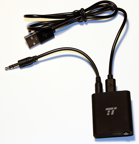
Figure 10-12 TauTronic external Bluetooth module.
All the components were situated on a tabletop for convenience. Figure 10-13 shows the main controller assembly with all the components interconnected with a solderless breadboard.
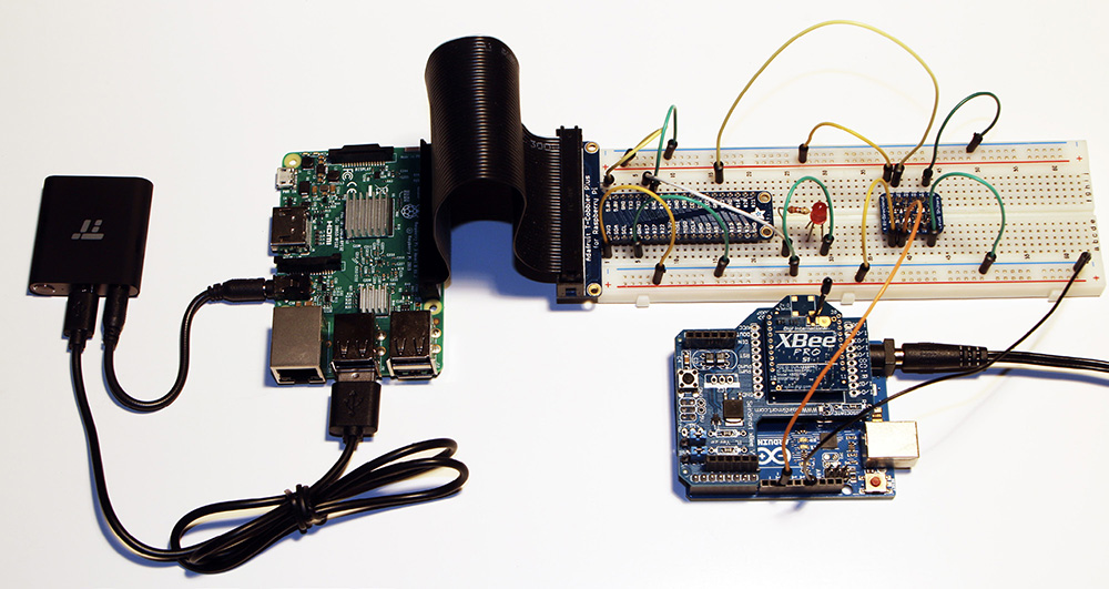
Figure 10-13 Complete main controller assembly.
You should now be ready for the main controller software installation once the preceding assembly steps have been completed.
Main Controller Software Installation There are two scripts to be discussed regarding the main controller software installation. The first is the Arduino code that is stored in the UNO, which has an XBee Shield connected to it. The second portion concerns the Python code stored on the RasPi, which responds to any alert/alarm sent to it by the UNO. The RasPi will then send an alert via the Bluetooth module to the Home device.
I downloaded and installed the Arduino IDE on the RasPi from https://www.arduino.cc/en/Main/Software. Just ensure that you select the Linux Arm version from the list shown on the right-hand side of the website, as shown in Figure 10-14.
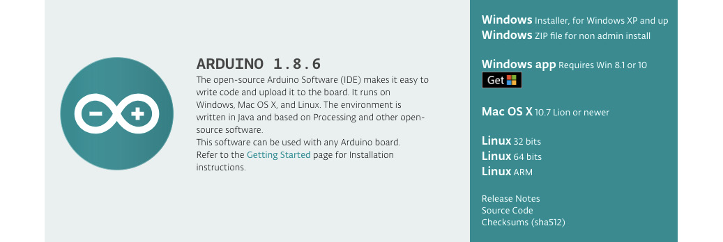
Figure 10-14 Arduino IDE installation on the RasPi.
Using the Arduino IDE directly with the RasPi makes the overall process of creating and loading software into the Uno very easy. I likewise found making any Arduino software modifications a snap by having the IDE natively installed. I highly recommend that you use this approach versus developing the software on a separate PC and then connecting the Uno to the RasPi and testing it out.
The Uno software script, which I named mainController.ino, is as follows:
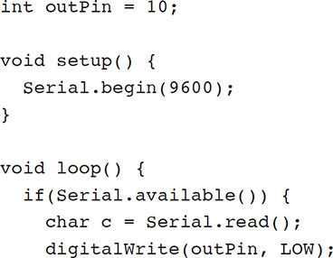
The script is very simple, with the Uno constantly receiving characters sent from the remote sensor hub with the single statement
char c = Serial.read();
The Serial class once again makes XBee data links exceedingly easy, as I mentioned in the remote sensor hub software installation discussion.
The script tests for a trigger value, which when detected will set an Uno GPIO pin high. This pin is also connected through a level-shifter chip to a RasPi GPIO pin. The RasPi constantly monitors or polls its GPIO pin to detect when it changes state from low to high. A Python script installed in the RasPi will then send an alert to the Home device via the external Bluetooth module, which is connected to the 3.5-mm audio output jack.
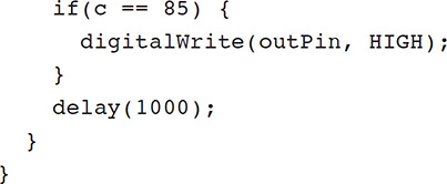
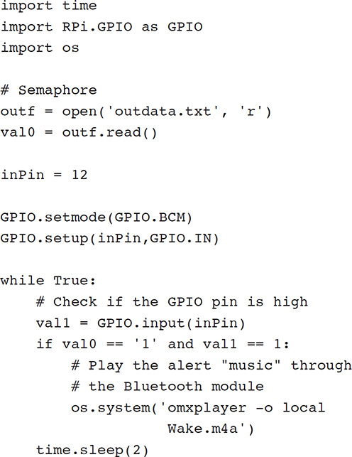
The Python script, which I named receiveTest.py, must be loaded into the RasPi. This script is as follows:
This script is also quite simple. The designated GPIO pin is constantly polled to check whether its state has changed from low to high. If changed, a system-level call is made, which, in turn, sends an audio file to the Home device indicating that the PIR sensor has been triggered. I actually used a music file to send as an alert to the Home device. You can use any mp3 or m4a file you want as an alert.
Systems Test I first tested the XBee wireless link by powering on the remote transceiver and monitoring the output using the integrated serial monitor. Just to reiterate, recall that the Serial.println(value); statement in the Arduino script causes the value both to be transmitted and also to appear on the serial monitor output screen, if so enabled. Figure 10-15 is a screen capture of the serial monitor screen.
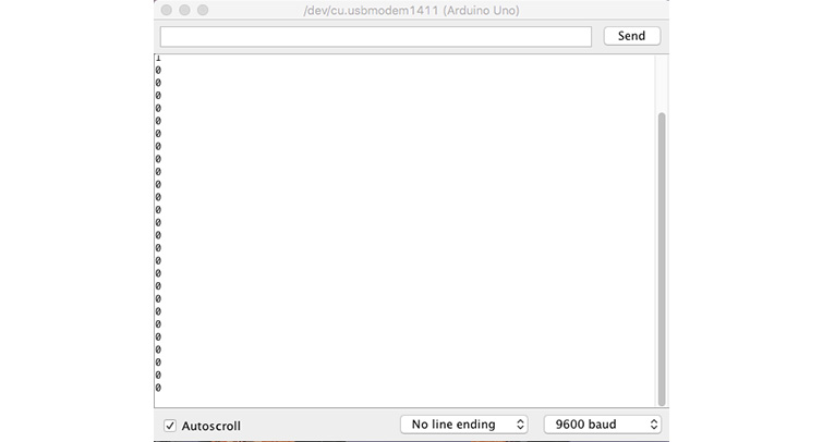
Figure 10-15 Remote sensor hub serial monitor screen.
You should be able to see the few 1’s that appear on the screen when I waved my hand in front of the PIR sensor.
The next step in the systems test was to confirm that the main controller XBee transceiver was receiving and processing the data sent from the remote sensor hub. I again used the serial monitor to review the received characters. Figure 10-16 is a screen capture of that serial monitor being run on the host RasPi.
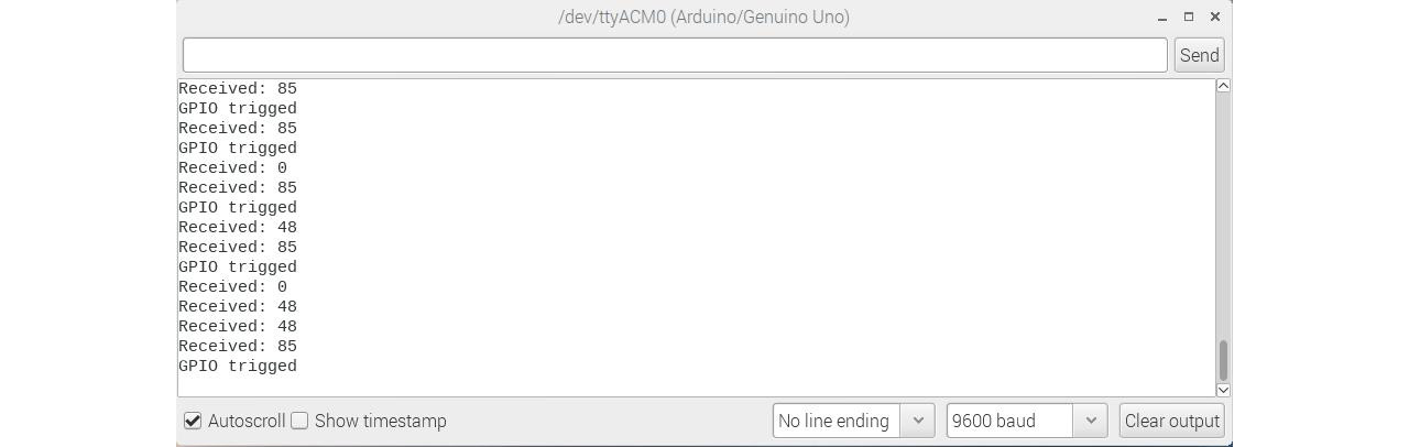
Figure 10-16 Main controller serial monitor screen.
You should be able to see all the GPIO trigger events that I generated by waving my hand in front of the PIR sensor. The displayed messages result from debug print statements that I placed in the development code and are not shown in the book listing.
At this point I have confirmed a working wireless communications link between the remote sensor hub and the main controller. The next step is test the response action of the RasPi on detecting an event sent by the remote sensor hub. This would mean installing and running the Python script described earlier. However, you must first pair the TauTronics module with the Home device in order to determine whether the audio file is successfully transmitted from the RasPi to the Home device. I accomplished this pairing operation quite easily using the Google Home app installed on my smartphone. The process is quite simple in that you first put the Home device in pairing mode using the app. The app quickly discovers the TauTronics device, and you click on the app, confirming that you want to pair it. That’s all that is needed for the pairing.
The Python script can now be run once the pairing operation is finished. Just load the script into the RasPi and run this command:
sudo python receiveTest.py
I was most pleased when I heard the alert “music” coming from the Home device after waving my hand in front of the PIR sensor. This last action completes the system tests, but I am not quite finished with this project because I have to discuss how to integrate the Web portion with the non-Web software.
Integrating All the Software
I provided a detailed discussion and demonstration of how to enable a security system using a voice command through a Home device. I next showed how to create a distributed security system in which a remote sensor triggered by infrared energy in a space could subsequently trigger an audio alert in a Home device. What I haven’t discussed is how to tie the Web actions to the distributed security system. This is actually a difficult problem because of the nature of the two concurrently running processes. One process is the RasPi Web server, which is constantly monitoring an incoming HTTP port and responding to any valid Web requests sent by the Home device. The other process is essentially a forever loop in the Python script that is constantly polling to check on the state of a specific GPIO pin. These processes are mutually exclusive and basically cannot run simultaneously. After much experimentation, I finally arrived at a partial solution, which is to use a semaphore or flag, which would be used as a signal between the two processes. This flag is only a single character, either a 0 or a 1, and is stored in an external data file I named outdata.txt. The Web server would store a 1 in the data file whenever it received a Web request to enable the security system. Likewise, it would store a 0 in the data file whenever the disable Web request was received.
Meanwhile, the Python script was modified to read the flag from the data file and only take action if the flag was set to 1. The critical modification I needed was to execute the Python script from within the Web server software whenever the security system was enabled by voice command. This modification worked, and I was able to run the complete system and generate alerts whenever the PIR sensor triggered. Unfortunately, I was not able to reinstate the Web server process once I initiated the Python script process. This is likely due to some complex interactions taking place at the Linux kernel level. This limitation is not too critical because all you need to do is reboot the RasPi, and it will restart the Web server without any issues.
The modified Web server script is listed next. I renamed it securityTestExtended to differentiate it from the previous version. Note that I removed many of the URL extensions not required for this project.
I have also listed the modified Python script below. It was renamed receiveTestExtended.py to differentiate from the earlier version.
It is my belief that it would be possible to have both processes running concurrently by incorporating a multithreaded approach. This approach would be quite complicated and probably unwarranted considering that this is a maker-style project and should be kept to a moderate level of complexity.
Extensions and Modifications
This security system obviously can be extended by adding additional sensors. The Web side of the code would not have to change, but the Python script controlling the system would have to be extended to incorporate all new sensors. These extensions would be easy if the sensors were binary, meaning on or off, just like the PIR sensor. However, the XBee system is fully capable of sending significant data over the link instead of simple 1’s and 0’s. In this case, it would not be hard to use analog sensors with the security system, including temperature or humidity sensors. In addition, you could easily add distance-measurement sensors such as Lidar units, which I have discussed in some of my other project books.
The system software could also be modified to incorporate a logging feature, where system status would be stored periodically in a log file along with a time stamp. This would provide a useful long-term feature for users wanting to examine the system environment over a prolonged period.
Summary
I started this chapter on HA security systems with a discussion of the basic concepts to be considered when designing and building a home security system. The nature of risk was examined, and I pointed out that while some things must be protected, others can be left alone because any adverse event associated with those items would be of low probability and not cost that much.
A discussion regarding the chapter’s project was next. This project involved a remotely mounted PIR sensor that was wirelessly connected to a RasPi controller. The whole system was turned on or enabled by a voice command spoken to a Google Home device.
I next discussed the overall system design, and the requirements were carefully detailed. Then a plan was created to meet those requirements. I also included a detailed discussion of the XBee electronics used to implement the wireless link between the remote sensor hub and the RasPi main controller assembly.
Several sections followed that included discussions concerning implementation of the hardware and software required for the system. There was also a discussion of how to set up the RasPi Web server software and associated Web applets needed for the voice control aspect of the project. This part of the discussion was based largely on the material presented in Chapter 2.
I next went through a comprehensive procedure regarding the Arduino and RasPi software required to operate the system. An initial systems test was shown, and the system was first enabled with a voice command, the PIR sensor was triggered, and finally, an alert (actually a music file) was heard from the Home device. I finished the chapter with a discussion of possible system extensions and modifications that reasonably could be made to further enhance the system.