
CHAPTER 6
Z-Wave and Home Automation
USING Z-WAVE IN A RASPI HA project is the intriguing subject for this chapter. I have mentioned Z-Wave in previous chapters because it is a predominant and proven technology that has been adopted by many HA device manufacturers. These companies include established brands such as GE, Black & Decker, Schlage, ADT, and Draper.
Z-Wave Fundamentals
Z-Wave is a wireless packet-based RF communications platform. It is somewhat similar to WiFi because the latter also uses RF and packets, but there are also significant differences. Z-Wave uses RF transceivers that operate at 908.42 megahertz (MHz) in the United States and at 860 MHz in Europe. These frequencies belong to the industrial, scientific, and medical (ISM) radio band, which is significantly separated from WiFi frequencies, which are either at 2.4 or 5.0 gigahertz (GHz). The ISM band is often subject to much less noise and interference than the higher frequency WiFi bands. A Z-Wave RF transceiver has a typical range of 100 meters (m), which is comparable with a WiFi node. It is also subject to the signal attenuation that occurs indoors owing to walls and doors interfering with the signal strength. Z-Wave signal extenders are available, just as there are WiFi signal extenders.
Parts List

A group of Z-Wave transceivers makes up a mesh, with each transceiver considered a node in that mesh. Each node can both receive and transmit digital packets. Nodes not only can originate data packets but also can receive and retransmit data packets from other nodes. This action is known as digipeating and is a very important property of a mesh network. A node that is digipeating is called a hop. Only four hops are allowed for any specific data packet because of regulatory concerns regarding unlicensed operation within the ISM band. All data packets are destroyed after the fourth hop in a process known as hop kill.
Z-Wave Network Basics
The Z-Wave data communications protocol is in compliance with the Open System Interconnection (OSI) seven-layer network model. The complete seven-layer model is shown in Figure 6-1.
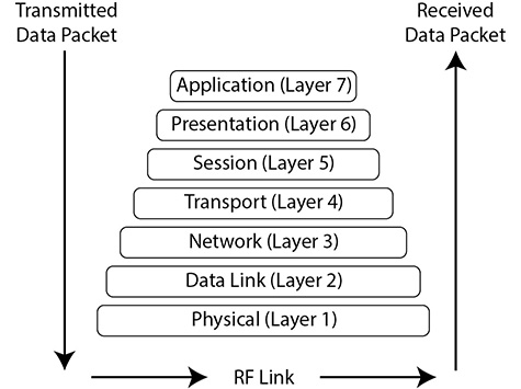
Figure 6-1 OSI seven-layer network model.
However, not all the model layers are implemented in the Z-Wave communications protocol. This is because the OSI model’s seven layers were designed to cover a host of different protocols, some of which are irrelevant for Z-Wave. Figure 6-2 shows the four layers that are implemented with remarks in each layer detailing the implementations.

Figure 6-2 Z-Wave-specific network model.
Layer 1 is the physical layer, which uses an ISM band RF transceiver to both send and receive digital packets. These packets are raw in nature in the sense that they are either decoded in the model upper layers for receive packets or simply sent out for the already formatted transmit packets from the upper layers. Every node has Carrier-Sense Multiple Access with Collision Detection (CDMA/CD) hardware, which determines when it is safe to transmit over the network. CDMA/CD has been compared with the very old-fashioned telephone party line, where a user would first pick up the headset and listen to determine if anyone was currently talking on the line. The user would then start the call if nothing was heard and otherwise hang up and try a little bit later. CDMA/CD does the same except that the time frame is in milliseconds rather than minutes, as would be the case for a party line.
Layer 2 is the data link, where a packet to be transmitted has a synchronization preamble along with a start-of-frame (SoF) byte prepended to the data payload sent from higher OSI levels. Additionally, an end-of-frame (EoF) byte is appended to the end of the data payload. Received packets are treated in the reverse manner; that is, the received raw data packet has its framing bytes removed before the data payload is sent upward to the higher OSI layers.
Layer 3 is the transport, where additional bytes are added to the data packet being prepared for transmit. These bytes depend on the active communication process. Z-Wave is a connection-type network, which has a very robust method of ensuring packet delivery. Layer 3 uses an acknowledgment (ACK) byte and negative acknowledgment (NACK) byte to maintain a continuous communications link. A node acting as a receiver will send back an ACK packet to the transmit node if it successfully receives a data packet. Likewise, it will send back a NACK if the packet was corrupted or somehow not completely received. This handshake will continue until the original packet is successfully sent or a preset limit of retries is reached, a so-called timeout operation. Using ACKs and NACKs depends on detecting errors in the data packet, which is why there are two checksum bytes included in every data packet. These bytes are used by the layer 3 implementation code to test the received data payload using a mathematical algorithm called the cyclic redundancy check (CRC). It should be apparent that layer 3 works mainly with receive packets to ensure a stable communications link. It must also generate the checksums for the transmit packets.
Layer 4 is for routing, where transmit packets have address information included in the packet to ensure that the packet arrives at the intended node. This layer also ensures that nodes will digipeat. Routing information is maintained in a table located in the primary network controller node. It is possible to have multiple primary controllers present in the network, but only one can be active at any given time. Figure 6-3 shows a simple network topology along with a routing table for that topology.
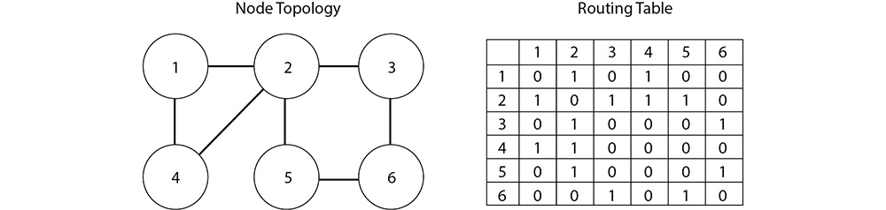
Figure 6-3 Simple mesh network topology with routing table.
You should be able to see that there is no direct connection between nodes 4 and 5. Any packets exchanged between the two must go through node 2 or the longer path from node 2 to node 3 to node 6. Note there is an even longer path—node 1 to node 2 to node 3 to node 6—but this path would never be taken because it involves four hops, and the packet would be dumped because of the four-hop restriction I mentioned earlier.
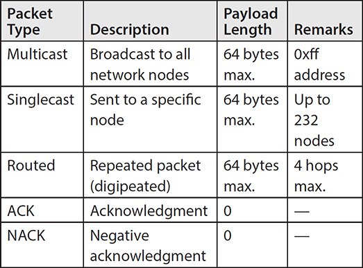
Layer 7 is the final one used in the Z-Wave network model, and it is the “highest” abstraction, the application layer. It is in this layer that the user inputs Z-Wave commands either through direct action such as a remote control or via program or script code. This layer is the user interface (UI), and it may be implemented in hardware, software, or a combination of both. Table 6-1 details the five different packet types used in a Z-Wave mesh network.
Table 6-1 Z-Wave Network Packet Types
Every Z-Wave network uses a 4-byte ID called the Home ID. Each primary controller has this Home ID, which slave nodes acquire when they join the network. Every secondary controller also uses the same Home ID when they are attached to the network. Individual slave nodes have a 1-byte ID that is assigned by the primary controller when that slave node joins the network.
Network Devices
Z-Wave network controllers and slaves are the two device types that comprise a Z-Wave network. Slaves are also known as end point devices because they only respond to the command packets sent by the controller. Slaves usually contain a microcontroller with GPIO pins that, in turn, control TRIAC (triode for alternating current) devices, which turn AC mains on and off. These GPIO pins are most likely to use optoisolators for maximum protection against inadvertent faults with the AC mains.
Figure 6-4 shows a Z-Wave-enabled duplex outlet I used for the next demonstration. It resembles an ordinary US duplex outlet except for the small push button between the sockets. Of course, the Z-Wave stamping on the front reveals the true nature of this device. This outlet is also about thirty times more expensive than an ordinary “dumb” duplex outlet, but you wouldn’t need to have all that many smart control points in your house.

Figure 6-4 Z-Wave-enabled duplex outlet.
The user must press the button on the duplex outlet to join the Z-Wave network when prompted by the controller device. I will demonstrate how to join the outlet shortly in a demonstration, but I next need to mention a few things regarding the network controllers.
Z-Wave network controllers are either portable or static. Portable controls resemble ordinary AV remote controls, as can be seen in Figure 6-5, which is a GE portable Z-Wave controller. These controllers must be able to self-discover their location within the network topology because they do not have the advantage of being placed in a fixed location. Such self-discovery is made possible by having the portable controller ping nearby nodes that are within their RF range. The controller can then join the network based on the results of the ping packet search. Portable controllers are battery powered and are often used as the primary controller within a Z-Wave network. The controller shown in the figure runs on three AAA batteries, which last a long time.
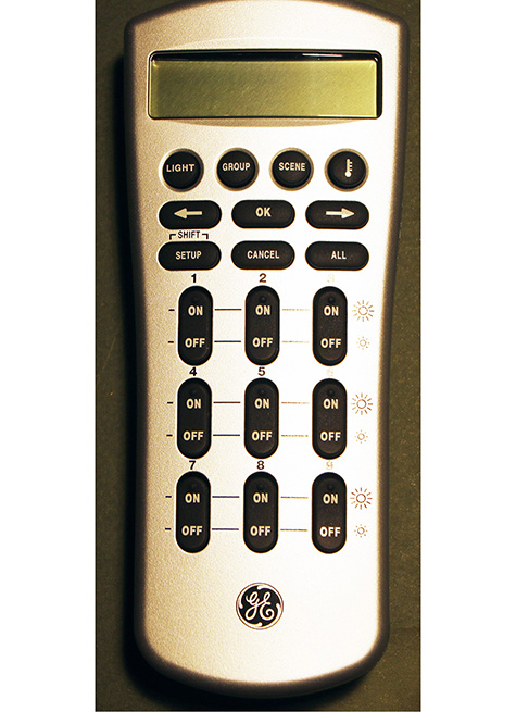
Figure 6-5 GE portable Z-Wave controller.
Static controllers are the other type, and they are so named because they are powered by AC mains and are situated in fixed locations. A static controller can easily monitor all the network traffic and often serves as a secondary controller in an advanced network configuration. The current network configuration may be stored in it, and if so, it is known as a static update controller (SUC).
Most often a static controller serves as a bridge between Z-Wave components and devices and non-Z-Wave devices, such as X-10 devices. The static controller acts as a virtual node when deployed in this manner, bridging and converting “foreign” data packets between the outside devices and the Z-Wave network.
A Z-Wave network may have up to 125 virtual nodes, which could be a great help in the case of a large HA system with many legacy devices and components that need to be converted to a Z-Wave network. Static controllers also may serve as TCP/IP gateways, thus allowing Z-wave network Internet connectivity.
Static controllers may act as primary controllers in cases where the normal primary controllers can be placed into a static control proxy situation. In such a setup, this advanced configuration is known as a SUC ID server (IS). I will not be using such a complex configuration in any book project, but it does suggest that a large variety of system configurations can be created using Z-Wave controllers.
The Z-Wave Microcontroller
The original Z-Wave chip was designed and manufactured by Zensys, now known as Sigma Designs. All certified Z-Wave component manufacturers must use this authentic Z-Wave chip in their devices. This ensures that any Z-Wave node properly joins the network and communicates with other nodes produced by other manufacturers. The Zensys chip design is discussed in this section because it forms the basis for the complete Z-Wave concept and provides a background for understanding how the RasPi can function as a controller in a network.
A recent Zensys single module is Model ZW3102N, containing a ZW0301 chip that uses the venerable 8051 core with a 32-MHz external crystal. This is a hybrid module containing a lot of additional components, including a RF transceiver operating on either the U.S. or European ISM frequency. There is also a built-in digital modem along with a hardware implementation of the network stack operations that were discussed in the preceding section. The ZW0301 chip has only 32 kilobytes (kB) of Flash memory and a meager 2 kB of static random access memory (SRAM). It operates on a supply voltage range of 2.1–3.6 V DC and consumes a maximum of 36 milliamperes (mA) when transmitting. Figure 6-6 is the block diagram of the ZW3102N showing all the components that constitute this module.
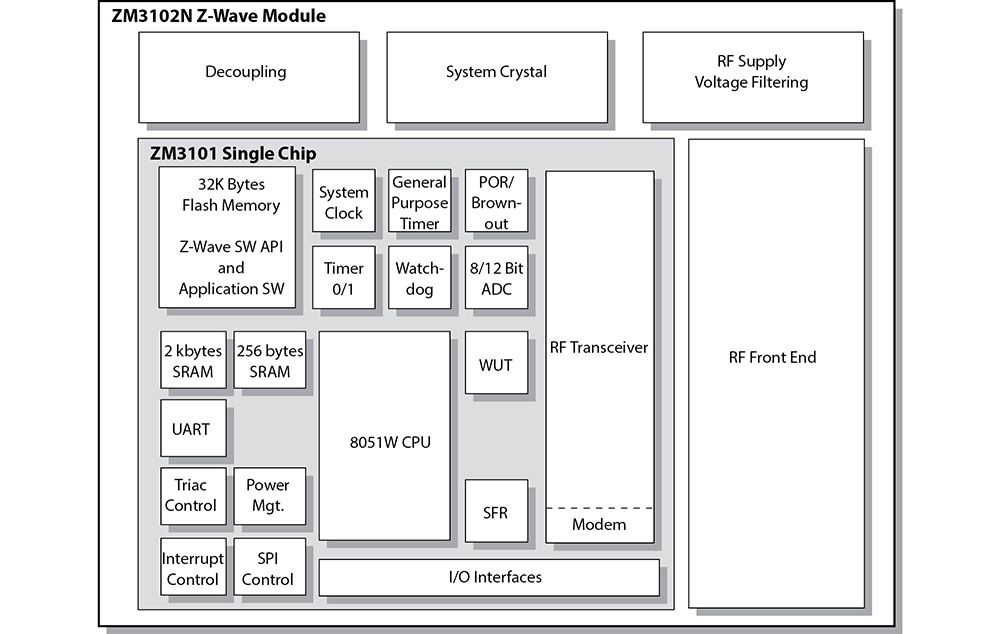
Figure 6-6 Block diagram of the ZW3102N module.
The ZW0301 chip has several of the standard functions that have been discussed in previous chapters, including the serial peripheral interface (SPI) and the universal asynchronous receiver/transmitter (UART) interfaces. The chip also has timers, interrupts, a watchdog monitor, power management, and brownout detection. It has a four-channel, 12-bit analog-digital converter (ADC), a pulsewidth-modulation controller, and an enhanced TRIAC control with zero crossing detection. A total of 10 GPIO lines are available, but some are multiplexed or shared with other I/O functions. The ZW3102N module is very small. Figure 6-7 shows the module with a U.S. quarter coin for comparison.
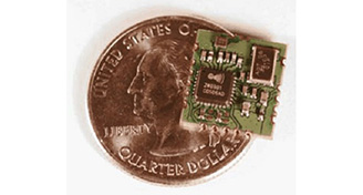
Figure 6-7 ZW3102N module.
The module does need an external antenna, and a few capacitors and inductors complete a Z-Wave device installation. The software is also fixed in the Flash memory and is not available for examination or modification. This where this chapter’s RasPi project will open up the Z-Wave network so that you have a chance to experiment with various configurations and monitor network traffic. But first I would like to demonstrate a simple Z-Wave network.
Z-Wave Demonstration
This demonstration uses a portable controller (shown in Figure 6-5) along with two nodes. One node is the duplex outlet shown in Figure 6-4, and the other is an outdoor module, as shown in Figure 6-8.
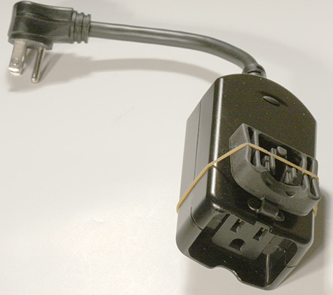
Figure 6-8 Z-Wave outdoor module.
Please notice the black button located on the top of the device in Figure 6-8. The user needs to press this button to join the device to the network when prompted by the controller menu.
The demonstration network nodes or slaves will be made up of the duplex outlet and outdoor module, each controlling a small table lamp. The duplex outlet will actually be connected to a power cord plugged into a regular outlet for this temporary test arrangement. Figure 6-9 shows the test setup on my dining room table.
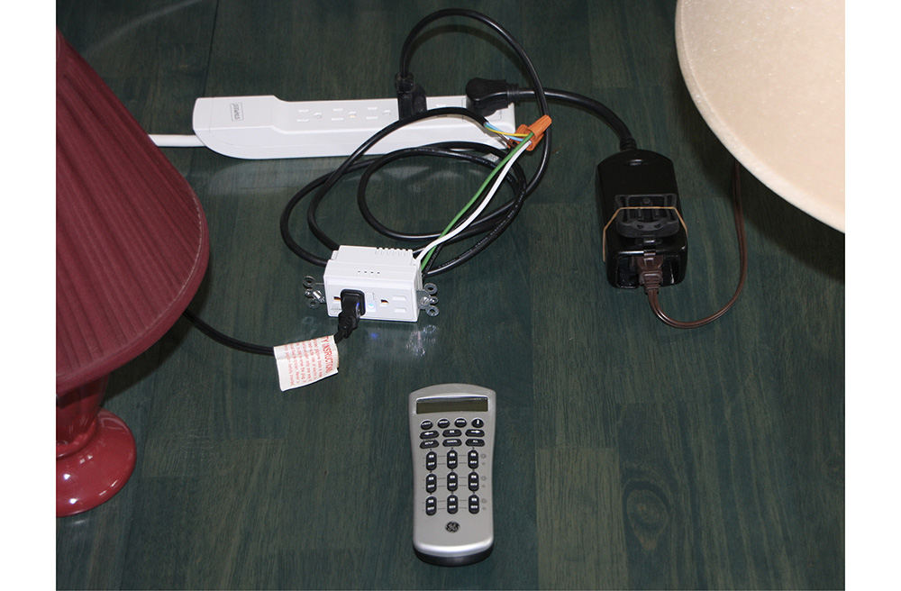
Figure 6-9 Z-Wave test system.
At first, I arbitrarily assigned device number 4 to the outdoor module and device number 8 to the duplex outlet. I then proceeded to turn the lamp on and off using the portable controller, and everything worked as expected. I was also able to control both devices simultaneously by selecting the “All” mode on the portable controller. The next part of the test was a bit harder because I have a smaller home with an open-plan layout, meaning that there are fewer interior walls than an average cape-style home. I was finally able to place the outdoor module device in the basement and the duplex outlet on the first floor, and I operated the controller in a second-floor bedroom. I was not able to turn on the basement module without having the first-floor module plugged in. This proved that the first-floor module was digipeating and forwarding the control packets to the module located in the basement. The controller showed “Failure” on its liquid-crystal display (LCD) screen with the first-floor module unplugged. This status indicates that no ACKs were being received. Obviously, no NACKs could be sent because the first-floor module was unpowered and the basement module was out of range.
Setting up this demonstration was very simple, and it amply shows that the high-tech Z-Wave network functioned well while providing the user with a very easy-to-use and useful interface. The next demonstration shows how to interface a RasPi with a Z-Wave network. This setup will allow for some interesting experiments.
RasPi and the Z-Wave Interface
Connecting a RasPi to a Z-Wave network requires the use of a Z-Wave USB dongle. One such device made by Aeon Labs, called the Z-Stick, is shown in Figure 6-10. It incorporates a Zensys module and a USB interface chip along with some additional firmware to make the two components work together. It also has an internal rechargeable battery that enables the storage of firmware updates and configuration data. The Z-Stick has three operating modes that you should know about:
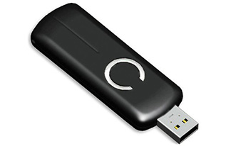
Figure 6-10 Aeon Labs Z-Stick.
![]() Inclusion. This mode adds or includes Z-Wave devices into the network. To add a device:
Inclusion. This mode adds or includes Z-Wave devices into the network. To add a device:
1. Unplug the Z-Stick from the USB connector.
2. Press the large button on the Z-Stick. The Z-Stick LED will start to slowly blink.
3. Go to the device that you wish to add while holding the Z-Stick, and press and release the device’s button.
4. The Z-Stick LED will blink rapidly for several seconds, then glow steadily for 3 seconds, and finally return to a slow blinking state. The device has been added to the network.
![]() Removal. This mode will remove or exclude Z-Wave devices from the network. To remove a device:
Removal. This mode will remove or exclude Z-Wave devices from the network. To remove a device:
1. Unplug the Z-Stick from the USB connector.
2. Press and hold the large button on the Z-Stick for about 3 seconds. The Z-Stick LED will start to blink slowly and then transition to a fast blink.
3. Go to the device that you wish to remove while holding the Z-Stick, and press and release the device’s button.
4. The Z-Stick LED will then glow steadily for 3 seconds and finally return to a fast blinking state. The device has been removed from the network.
![]() Serial API. This is the mode where the Z-Stick acts as the portal between the RasPi and the Z-Wave network. Simply plug it into a powered hub USB connector because the RasPi does not have sufficient power for the Z-Stick. RasPi software will now take control of the Z-Wave network.
Serial API. This is the mode where the Z-Stick acts as the portal between the RasPi and the Z-Wave network. Simply plug it into a powered hub USB connector because the RasPi does not have sufficient power for the Z-Stick. RasPi software will now take control of the Z-Wave network.
I now have to take a brief detour from the Z-Wave to introduce the Secure Shell login process that will be used in establishing the control software environment.
SSH Login
In this section, I will show you how to log onto the RasPi using a network connection. The Stretch Linux distribution, as well as many others, includes a great service known as Secure Shell (SSH). It is a network protocol that uses cryptographic means to establish secure data communication between two networked computers connected via a logical secure channel over a physically insecure network. SSH uses both server and client programs to accomplish the connection.
One of the questions that arises when you are first configuring your RasPi is whether or not to start SSH on boot-up. I recommended that you answer yes because that automatically starts the SSH daemon each time you start the RasPi. The second part of the connection is the client program, which is highly dependent on the type of computer you are using to connect to the RasPi. I recommend using putty.exe because most of you will be using a Windows-based machine. Putty is freely available from a variety of Internet sources, so I would recommend a Google search to locate a good download mirror. You should see the Figure 6-11 screenshot, assuming that you answered yes to the SSH question and have downloaded and are running Putty on a Windows-based computer connected to the same network that connects to the RasPi.
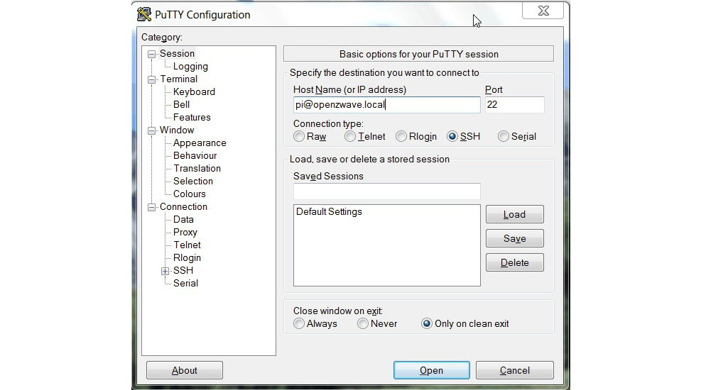
Figure 6-11 Putty screenshot.
Don’t be concerned with the host name that appears in the screenshot; I will get to that shortly. When you click on the Open button at the bottom of the Putty screen, you will see a screenshot of a RasPi terminal window asking, in this case, for a login password (Figure 6-12).

Figure 6-12 RasPi terminal window.
At this point, you are in a RasPi terminal window session—absolutely no different from looking at a monitor connected directly to a RasPi and using a locally connected keyboard and mouse. This transparency is what makes SSH so great; it allows you to remotely log in to the RasPi without being concerned with any minutiae about the connection. You may type in any normal command and have the RasPi respond as appropriate.
I will now return to my Z-Wave software discussion, now that you are familiar with SSH.
Project Things by Mozilla.org
Project Things is a software framework consisting of applications, utilities, and services that can connect smart HA devices to computers and microcontrollers such as the RasPi. The latest implementation of Project Things is called the Things Gateway. It will allow you to directly control and/or monitor HA devices and appliances over the Web. It can replace all the separate mobile apps that can quickly accumulate for individual HA devices, systems, and appliances. Mozilla has made available a full RasPi Debian Linux distribution that contains the Things Gateway preinstalled and ready for deployment. You will need to use an OpenZWave-compatible dongle (adapter) to be able to communicate with any existing Z-Wave devices. I used an older Aeon Labs Z-Stick S2 dongle that I had from use in previous projects. You can also use this if it still available; otherwise, use either one of the following:
![]() Sigma Designs UZB Stick
Sigma Designs UZB Stick
![]() Aeotec Z-Stick (Gen5)
Aeotec Z-Stick (Gen5)
Ensure that the stick uses the correct frequency for your region, which I discussed in an earlier section.
Software Installation
Much of the following discussion is based on a blog tutorial written by Ben Francis that is available at https://hacks.mozilla.org/2018/02/how-to-build-your-own-private-smart-home-with-a-raspberry-pi-and-mozillas-things-gateway/. The first thing you will need to do is to download the disk image from https://iot.mozilla.org/gateway. The current gateway was version 0.4 at the time of this writing.
Next, create a bootable micro SD card using the procedures discussed in Chapter 1. Mozilla also has instructions on how to run the gateway software on a PC or Mac if you are inclined to experiment. However, I will be staying with the RasPi installation for this book.
The gateway software will start a WiFi hot spot with the SSID name of Mozilla IoT Gateway. You should join this network in order to connect the RasPi to your own WiFi network. If you are using another computer on your network or a smartphone, the Mozilla IoT Gateway will show all the local WiFi networks detected, as shown in the Figure 6-13 tutorial example. Select your regular network, and enter the passkey or pass phrase for a secured network.
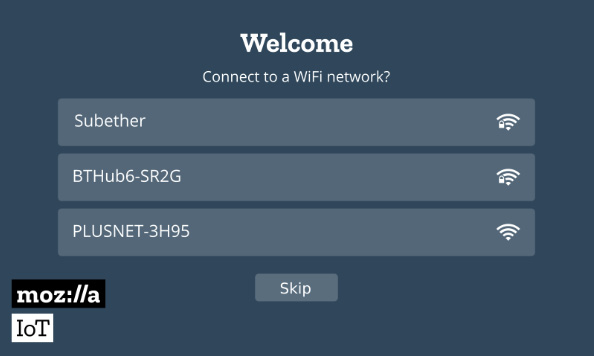
Figure 6-13 WiFi network selection.
If you are using the RasPi browser, go to http://gateway.local/ and start the setup process. Figure 6-14 shows the screen you will see while the gateway connects to your WiFi network.

Figure 6-14 Connecting to the local WiFi network.
You will be asked to enter a unique subdomain name once you are connected to the gateway URL. You will also need to enter an e-mail address, which will enable you to retrieve your subdomain name at any future time. The subdomain name is used, in part, to generate an Secure Sockets Layer (SSL) certificate, which, in turn, is used to establish a secure Internet tunnel so that you can remotely access the gateway. Figure 6-15 shows the screen for entering these data.
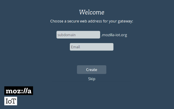
Figure 6-15 Data entry for secure gateway address.
After setting the secure gateway address, you will be placed into your new subdomain, and another dialog box will appear, where you will enter data to create an account in the gateway. This data consist of your name, e-mail address, and password. Figure 6-16 shows this account setup screen.

Figure 6-16 Account setup screen.
This last step completes the gateway configuration/setup, and you will now see an Add Things screen, as shown in Figure 6-17. How to add things is the subject for the next section.

Figure 6-17 Add Things screen.
Add Things
You add things to the gateway by clicking on the “+” icon located at the lower right-hand corner, as shown in Figure 6-17. I did this, and Figure 6-18 shows the things or devices that were discovered.

Figure 6-18 Discovered Z-Wave devices.
Any discovered device must be linked or paired subsequently with the gateway. This is easily done with Z-Wave devices by following the procedure I detailed earlier. When the pairing is completed, click on the Done button shown in the figure, and the newly paired devices will appear on the Things screen, as shown in Figure 6-19.

Figure 6-19 Things screen.
Test Run
The Z-Wave test of the gateway system was rather simple. I simply plugged an AC lamp into the outdoor Z-Wave device and turned the lamp on and off by clicking on the Switch icon shown in the figure. Incidentally, I am unsure what the Z-Wave-16a124a-4-Sensor icon shown in the figure refers to. It may be an undocumented feature for the switching device. In any event, clicking on it did not cause an action to be observed regarding the AC lamp plugged into the switch.
Summary
I started this chapter with a definition of home automation and provided a list of representative tasks that would fall under the broad umbrella that comprises home automation.
Next was a discussion of the underlying base technologies that support HA implementations. I provided a rationale for selecting the Z-Wave protocol because it is a modern, highly flexible system that is very easy to configure and lends itself quite well to a simple RasPi interface connection.
Two representative Z-Wave devices were described next, along with a working small-scale Z-Wave network. A network demonstration was created using a commercial portable controller device.
The core Z-Wave chip was discussed to provide you with a better understanding of how the overall network functions and how devices are highly dependent on the chip functions to be added seamlessly to the network. A Z-Stick was shown that enables a RasPi to Z-Wave interface to be implemented. Several alternatives to the Z-Stick were also discussed
I next showed you a highly useful SSH remote login procedure that you can use to access the RasPi while the open-source Z-Wave software is running. The open-source software executes as a Web service, thus making the RasPi GUI inaccessible. Any user access to the RasPi must then be done using a remote access service such as SSH.
I used the Project Things framework by Mozilla to create a gateway to control the Z-Wave devices introduced earlier in the chapter. This project’s version generates a gateway that you use to access and control Z-Wave devices. The Z-Stick is used to communicate between the RasPi and any nearby Z-Wave devices. I went through a detailed discussion of how to install and configure the gateway. The chapter ended with a simple demonstration of turning an AC lamp on and off using commands sent through the gateway.