
3
ELECTRICAL CIRCUITS

We’ve covered certain aspects of computing at a conceptual level; now let’s change direction and take a look at the physical foundations of computing. Let’s begin by reviewing our definition of a computer. A computer is an electronic device that can be programmed to carry out a set of logical instructions.
Computers are devices that follow rules designed by humans, but ultimately computers must behave according to another set of rules: the laws of nature. A computer is just a machine, and like all machines, it takes advantage of natural laws to accomplish a task. In particular, modern computers are electronic devices, so the laws of electricity are the natural foundation upon which these devices are built. To gain a well-rounded understanding of computing, you need to have a grasp of electricity and electrical circuits; that’s what we cover in this chapter. Let’s begin with electrical terms and concepts, learn some laws of electricity, cover circuit diagrams, and finally construct some simple circuits.
Electrical Terms Defined
For us to discuss electrical circuits, you first need to become familiar with several key concepts and terms. I’ll now cover these concepts of electricity and explain how they relate to each other. This section is packed with details, so let’s begin with an overview, in Table 3-1, before jumping into the particulars.
Table 3-1: Summary of Key Electrical Terms
Term |
Explanation |
Measured in |
Water analogy |
|---|---|---|---|
Electric charge |
Causes matter to experience a force |
Coulombs |
Water |
Electric current |
The flow of charge |
Amps |
Flow of water through a pipe |
Voltage |
The difference in electric potential between two points |
Volts |
Water pressure |
Resistance |
A measure of the difficulty for current to flow through a material |
Ohms |
The width of a pipe |
Table 3-1 gives a simple explanation of each term, lists its unit of measurement, and relates each term to its analog in a water-based system (shown in Figure 3-2, later in this chapter). If this doesn’t immediately make sense, don’t worry! We cover each term in greater depth in the following pages.
Electric Charge
In school, you may have learned that atoms are composed of positively charged protons, negatively charged electrons, and neutrons with no charge. Electric charge causes matter to experience a force; charges that are not alike attract, whereas like charges repel. When explaining the concepts of electrical circuits, I like to use an analogy of water flowing through a pipe. In this analogy, electric charge is like water, and a wire is like a pipe.
The unit of measurement for charge is the coulomb. The charge on a proton or electron is a tiny fraction of the quantity of charge represented by a single coulomb.
Electric Current
Of particular relevance to our discussion is the transfer or movement of electric charge, known as electric current. This flow of charge through a wire is similar to the flow of water through a pipe. In everyday usage, including in this book, we say that “current is flowing” or that “current flows,” although more precisely it’s charge that flows, and current is a measurement of the intensity of that flow.
When representing current in an equation, the symbol I or i is used. Current is measured in amperes, sometimes just called amps, abbreviated as A. One ampere corresponds to one coulomb per second. Let’s say you have two wires, the first with 5A flowing through it, and the second with 1A flowing through it. Since amps represent a rate, the first wire has electric charge moving through it at five times the rate of the second wire.
Voltage
Since charge flows through a wire like water through a pipe, let’s expand that analogy further. So far, we have water (electric charge), a simple pipe (a copper wire), and the rate of water flow (electric current). To that, let’s add a pump, connected to the pipe that moves water through the pipe. The greater the water pressure, the faster the water flows through the pipe. Relating this to electrical circuits, the water pump represents a power source, a source of electrical energy, such as a battery.
Water pressure in this analogy represents a new concept: voltage. Just as water pressure influences the rate at which water flows through the pipe, voltage influences current—the rate at which charge flows through a circuit. To understand voltage, recall from science class that potential energy, measured in joules, is the capacity for doing work. In the case of electricity, work means moving a charge from one point to another. Electric potential is potential energy per unit of electric charge, measured in joules per coulomb. Voltage is defined as the difference in electric potential between two points. That is, voltage is the work required per coulomb to move a charge from one point to another.
When representing voltage in an equation, the symbol V or v is used. Voltage is measured in volts, also abbreviated as V. Voltage is always measured between two points, such as the positive and negative terminals of a battery. A terminal, in this context, means an electrical connection point. The higher the voltage, the greater the “pressure” to move charge through a circuit from one terminal to another, and therefore the higher the current when a voltage source is connected in a circuit. However, a voltage can exist even if no current is flowing. For example, a 9-volt battery has a voltage of 9V across its terminals even when it isn’t connected to anything.
Resistance
Let’s go back to our water analogy. Another factor that affects the water flow is the width of the pipe. A very wide pipe allows water to flow in an unrestricted manner, but a narrow pipe impedes the flow. If we apply this analogy to circuits, the pipe’s width represents electrical resistance in a circuit. Resistance is a measure of the difficulty for current to flow through a conductor—a material that allows the flow of current. The higher the resistance of a material, the harder it is for current to flow through it.
When representing resistance in an equation, the symbol R is used. Resistance is measured in ohms, abbreviated as Ω (the Greek letter omega). A copper wire has very low resistance; for our purposes, let’s treat it as if it has no resistance at all, meaning current can freely flow through it. An electrical component called a resistor is used in circuits to introduce specific amounts of resistance where needed. See Figure 3-1 for a photo of a typical resistor.

Figure 3-1: A resistor
Water Analogy
Now that we’ve covered key electrical concepts, let’s revisit the water analogy we’ve been using to explain how electrical circuits work, as shown in Figure 3-2.
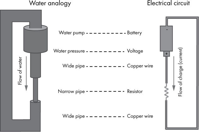
Figure 3-2: An electrical circuit described using a water analogy
The water pump moves water through a pipe, like a battery moves charge through a circuit. Just as water flows, so does electric charge; we call this current. Water pressure affects the rate at which water flows, and in the same way, voltage affects current—higher voltage means greater current. Water flows freely through a wide pipe, as current does through a copper wire. A narrow pipe restricts the flow of water, just as a resistor restricts current.
Now let’s apply what you’ve learned to an example circuit consisting of a battery with a conductor attached to its terminals. Potential energy is stored in the battery. The voltage across the terminals of that battery is a certain number of volts and represents a difference in electric potential. When the conductor is attached to the terminals of the battery, the voltage acts like a pressure that moves charge through the conductor, creating a current. The conductor has a certain resistance; a low resistance results in a larger current, and a high resistance results in a smaller current.
Ohm’s Law
The particulars of the relationship between current, voltage, and resistance is defined by Ohm’s law, which tells us that the current flowing from one point to another is equal to the voltage across those points divided by the resistance between them. Or stated as an equation:
I = V / R
Let’s say that you have a 9-volt battery with a 10,000Ω resistor attached across its terminals. Ohm’s law tells us that the current flowing through that resistor will be 9V / 10,000Ω = 0.0009 amps, or 0.9 milliamps (mA). See Table 1-2 for a reminder of why we use the “milli-” prefix here. Note that in this chapter, we’re using base 10 again, so you can take off your base 2 hat and think about numbers like a normal human for a while!
Circuit Diagrams
When we are describing electrical circuits, a diagram can be a very helpful visual aid. Circuit diagrams are drawn using standard symbols to represent various circuit elements. The lines connecting those symbols represent wires. Let’s take a look at how some common circuit elements are represented in diagrams. Figure 3-3 shows the symbols for a resistor and a voltage source, such as a battery. The + indicates the positive terminal of the voltage source, and the – indicates the negative terminal. Said another way, the + terminal has a voltage that is positive in relation to the – terminal.

Figure 3-3: The symbols for a resistor (left) and voltage source (right)
Using these two symbols, we can draw a circuit diagram that represents our example circuit from earlier (a 9-volt battery with a 10,000Ω resistor attached across its terminals). This diagram is shown in Figure 3-4. Note the 10kΩ designator on the resistor; this is shorthand for 10,000Ω (in other words, k is for kilo-, or thousand). Given our earlier Ohm’s law calculation, we know that 0.9mA of current is flowing through the resistor, so that is indicated on the diagram as well.
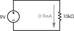
Figure 3-4: A 9-volt battery with a 10,000Ω resistor attached across its terminals
We can also illustrate the current as a loop, as shown in Figure 3-5. This visual helps convey the idea that the current flows through the entire circuit, not just the resistor.

Figure 3-5: The flow of current illustrated as a loop
Speaking of loops, this is a good time to take a step back and revisit a term that has already been mentioned several times but I haven’t yet defined. An electrical circuit is a set of electrical components connected in such a way that current flows in a loop, from the power source, through the circuit elements, and back to the source. Electricity aside, the general term circuit means a route that starts and finishes at the same place. This is an important concept to remember, because without a circuit, current will not flow. A circuit with a break in the loop is called an open circuit, and when a circuit is open, no current flows. On the other hand, a short circuit is a path in a circuit that allows current to flow with little or no resistance, usually unintentionally.
EXERCISE 3-1: USING OHM’S LAW
Take a look at the circuit in Figure 3-6. What is the current, I? The answer is in Appendix A.
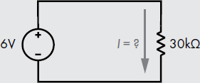
Figure 3-6: Find the current using Ohm’s law.
In the context of DC circuits, ground, sometimes abbreviated GND, refers to a point we measure against other voltages in the circuit. In other words, ground is considered 0V, and we measure other voltages in the circuit relative to it. As we covered earlier, we always measure voltage between two points, so it’s the difference in potential that matters, not the potential at a single point. By assigning ground as a reference point of 0V, we make it easier to talk about the relative voltage at other points in the circuit. In simple DC circuits like the ones we’re discussing here, it’s common for the negative terminal of the battery or other power source to be considered ground.
The term ground comes from the fact that some circuits are physically connected to the earth. They are literally connected to the ground, and that connection serves as a 0V reference point. Portable or battery-powered devices usually do not have a physical earth connection, but we still refer to a designated 0V reference point in those circuits as ground.
Sometimes engineers do not draw circuit diagrams as a loop; instead, they specifically identify the ground and voltage source connections with the symbols shown in Figure 3-7. This makes for cleaner diagrams, but it doesn’t change how the circuit is physically wired; current still flows from the positive to the negative terminal of the power source.

Figure 3-7: Symbols for ground (left) and a voltage source relative to ground (right)
As an example, in Figure 3-8 the circuit we discussed earlier is shown on the left, and on the right the same circuit is shown using the ground and voltage symbols introduced in Figure 3-7.
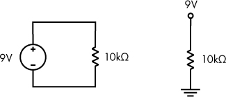
Figure 3-8: These two circuits are equivalent.
The two circuits in Figure 3-8 are functionally equivalent; only the diagram representation differs.
Kirchhoff’s Voltage Law
Another principle that explains the behavior of circuits is Kirchhoff’s voltage law, which tells us that the sum of the voltages around a circuit is zero. This means that if a voltage source supplies 9V to a circuit, then the various elements in that circuit must collectively “use” 9V. Each element around the circuit loop causes a decrease in electric potential. When this happens, we say that voltage is dropped across each element. Let’s look at the circuit in Figure 3-9 as an example.
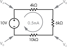
Figure 3-9: A circuit illustrating Kirchhoff’s voltage law
In Figure 3-9 we have a 10-volt power supply connected to three resistors in a circuit. When resistors are connected along a single path (in series), the total resistance is simply the sum of the individual resistance values. In this case, that means that the total resistance is 4kΩ + 6kΩ + 10kΩ = 20kΩ. Using Ohm’s law, we can calculate the current through this circuit as 10V / 20kΩ = 0.5mA. The circuit has four points at which we could measure voltage, labeled as VA, VB, VC, and VD. We’ll determine the voltage at each point relative to the negative terminal of our power supply.
Let’s begin with the easy ones: VD is directly connected to the negative terminal of the power supply, so VD = 0V, or ground. Similarly, VA is connected to the positive power terminal, so VA = 10V. Now we know from Kirchhoff’s voltage law that the resistors are each going to cause a voltage drop, so VB must be something less than 10V, and VC must be something less than VB.
How much voltage is dropped across the 4kΩ resistor? Ohm’s law says that V = I × R, so the voltage drop is 0.5mA × 4kΩ = 2V. That means that VB will be 2V less than VA. So, VB = 10 – 2 = 8V. Similarly, the voltage drop across the 6kΩ resistor will be 3V. Therefore, VC = 8 – 3 = 5V. Without even doing the math, we know from Kirchhoff’s voltage law that 5V must be dropped across the 10kΩ resistor, since it’s the final circuit element before the negative terminal, at 0V. In Figure 3-10, our diagram is updated with voltages and voltage drops.

Figure 3-10: Voltage drops around a simple circuit
To recap this example, a voltage source supplies 10V, which we consider a positive voltage. The resistors each cause a drop in voltage, and we consider these voltage drops negative. If we sum the positive voltage source with the negative voltage drops, we get 10V – 2V – 3V – 5V = 0V. The sum of the voltages around the circuit is 0, which is consistent with Kirchhoff’s voltage law.
You may wonder if this only works with certain values of resistors. After all, the math worked out very nicely in the example given, perhaps a little too nicely! In the following exercise, we change one of the resistors in the example circuit from 4kΩ to 24kΩ, and you can see that Kirchhoff’s voltage law still holds true.
EXERCISE 3-2: FIND THE VOLTAGE DROPS
Given the circuit in Figure 3-11, what is the current, I? What is the voltage drop across each resistor? Find the labeled voltages: VA, VB, VC, and VD, each measured as relative to the negative terminal of the power supply. The answer is in Appendix A.
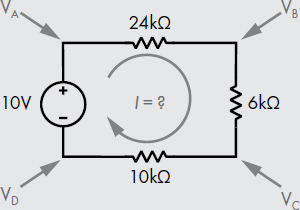
Figure 3-11: Another circuit illustrating Kirchhoff’s voltage law
Circuits in the Real World
Let’s look at how our simple 9V/10kΩ circuit (from Figure 3-4) can be constructed in the real world. In the photo in Figure 3-12, I’ve attached a 10kΩ resistor to a 9-volt battery using alligator clips.
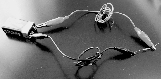
Figure 3-12: A 10kΩ resistor attached to a 9-volt battery using alligator clips
This approach works, but there are better ways to build circuits. A breadboard is a base for prototyping circuits. Historically, boards like those used for baking bread were used for this purpose, but unfortunately today’s breadboards don’t have anything to do with bread! A breadboard (Figure 3-13) allows for easy connections of various electrical components.
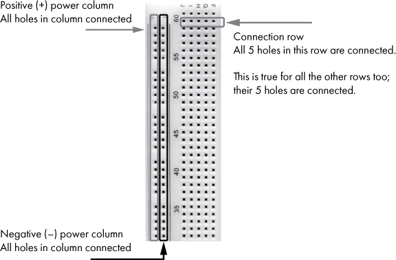
Figure 3-13: A section of a breadboard
As shown in Figure 3-13, along the edges of the breadboard are long columns usually labeled with + and –. These columns are often color coded as well, red for positive and blue for negative. All the holes along such an edge column are electrically connected, and the columns are intended to be used to provide power to the circuit, so typically your battery or other power source is connected to these columns. Likewise, the rows of typically five holes (in Figure 3-13, these are to the right of the edge columns) are also connected. Two components can be connected by simply putting an end of each component in the same row. No soldering, clips, or electrical tape required!
Figure 3-14 is a photo of the circuit shown in Figure 3-4 built on a breadboard.
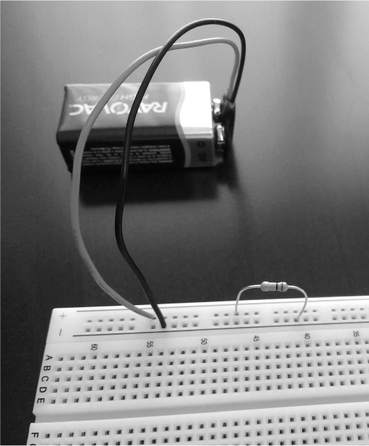
Figure 3-14: A simple circuit built on a breadboard
As you can see, this is a neater and simpler way of connecting electrical components. I optimized a bit by putting the ends of the resistor into the power columns to connect it directly to the battery.
NOTE
Please see Project #1 on page 45 to do the first project in this book! The previous exercises asked you to work through a problem mentally, whereas the projects ask you to do a little more, and this includes acquiring some hardware. There’s some effort and cost associated, to be sure, but I believe getting your hands dirty, so to speak, is the best way to really understand the concepts covered in this book. Turn to the end of this chapter to find the projects section. There you can build your own circuit!
Light-Emitting Diodes
The simple circuits we’ve discussed so far illustrate the basics of current and voltage, but they don’t do anything visually interesting. I’ve found that the simplest way to turn a dull circuit into a delightful circuit is to add a light-emitting diode (LED). A photo of a typical LED is shown in Figure 3-15.

Figure 3-15: An LED
Let’s cover LED basics and then add one to a circuit. The “light-emitting” part of the name is self-explanatory; this is a circuit element that emits light. Specifically, it’s a diode that emits light. A diode is an electronic component that allows current to flow through it in only one direction. Unlike a resistor that allows current to flow in either direction, a diode has very low resistance in one direction (allowing current flow), and very high resistance in the other direction (impeding current flow). An LED is a special kind of diode that also lights up when current flows through it. LEDs are available in multiple colors. The circuit diagram symbol for an LED is shown in Figure 3-16.

Figure 3-16: The symbol for an LED
To get an LED to emit light, we need to ensure the right amount of current flows through it. A standard red LED is rated for a maximum current of about 25mA; we don’t want to exceed that maximum current, since doing so can damage the LED. Let’s target 20mA as the amount of current we want to flow through our LED. A lower current value will still work, but the LED won’t be as bright.
So how do we ensure that the right amount of current flows through our LED? We just need to choose an appropriate resistor to limit the amount of current in our circuit. But before we can do that, you need to know about one more property of the LED, forward voltage, which describes how much voltage is dropped across the LED when current flows through it. A typical red LED has a forward voltage of about 2V. Forward voltage is often notated as Vf.
Our circuit diagram with a battery, LED, and resistor to limit current is shown in Figure 3-17. The diagram also shows the desired current of 20mA.
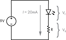
Figure 3-17: A basic circuit with an LED
In Figure 3-17, we have a 9-volt battery, an LED with a forward voltage of Vf, and a resistor with a resistance value of R. The voltage drop across the resistor is VR. Keep in mind that the voltage drop across the resistor varies with the amount of current that flows through it, unlike the LED, where the voltage drop is defined by its forward voltage property. In our previous circuit that only had a battery and a resistor (Figure 3-4), the entire 9V was dropped across the resistor. Now that we have two circuit elements connected to our battery, Kirchhoff’s voltage law tells us that part of the voltage will drop across the LED and the rest of the voltage will drop across the resistor. As a reminder, you can think of the battery as supplying the voltage, and the other elements as using the voltage. If we apply this to our circuit (Figure 3-17), Vf + VR = 9V.
Assuming we are using an LED with a standard forward voltage of 2V, VR = 9V – 2V = 7V. Let’s update our diagram with those voltage values, as shown in Figure 3-18.
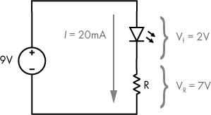
Figure 3-18: A basic circuit with an LED, voltage drops shown
That leaves us with only one unknown, R, the resistance of the resistor. We can calculate that using Ohm’s law: I = V / R, or R = V / I. So that gives us R = 7V / 20mA = 350Ω. And with that, we have the final piece of our puzzle on how to ensure that the right amount of current flows through our LED. We need a resistor of about 350Ω connected to our battery and LED.
NOTE
Please see Project #2 on page 50, where you can build an LED circuit yourself and see it light up!
Summary
In this chapter, we covered electrical circuits, the physical foundation of modern computing devices. You learned about electrical concepts such as charge, current, voltage, and resistance. You were introduced to two laws that govern the behavior of electrical circuits—Ohm’s law and Kirchhoff’s voltage law. You learned about circuit diagrams and how to construct your own circuits. Understanding the basics of electrical circuits will help you gain a foundational-level perspective on how computers work. The next chapter introduces digital circuits, bringing together the concepts of binary logic and electrical circuits.
PROJECT #1: BUILD AND MEASURE A CIRCUIT
You now know enough to build your own circuit. There’s no better way to learn than trying things yourself! To get started, you’re going to need some hardware, all of which you can purchase online or at a local electronics store, if you’re lucky enough to have one nearby. See “Buying Electronic Components” on page 333 for help getting these parts. Here’s what you’ll need for this project and the next:
Even at the low voltage levels we are working with, there is a small risk of a circuit component getting hot to the touch. With that in mind, I recommend that you disconnect your power source, a battery in this case, while hooking things up, and only connect power as the final step of assembling your circuit.
Once you have your components, connect everything together:
The wiring of a 9-volt battery clip is sometimes flimsy, which makes it rather hard to insert into a breadboard. If you run into this problem, try connecting one end of a jumper wire to the flimsy battery wire and the other end to the breadboard. You can connect the two wires with electrical tape or alligator clips (see Figure 3-19), or you can even solder them together if you know how to use a soldering iron. If you try any of these methods, take care to keep the metal parts of the negative and positive wires separate. Accidentally connecting them will short circuit the battery, which will make the wires very warm and quickly drain the battery.

Figure 3-19: Using alligator clips and jumper wires to overcome flimsy 9-volt battery clip wiring
You may be wondering how to determine the ohm value of a resistor. Resistors are color-coded; the bands depict multipliers, and the colors represent numeric values. Many free resistor color code calculators and charts are online, so I won’t go into the details here. For a 10kΩ resistor, look for a resistor with brown, black, and orange bands, in that order. The fourth band will usually be gold or silver, indicating the manufacturer’s tolerance, the allowed deviation from the stated value.
Now you have your circuit built, but how can you tell if anything is happening? Unfortunately, this circuit doesn’t visually indicate that it’s working, so it’s time to break out the multimeter and measure its various properties. To use a multimeter, you’ll need two test leads (the cables used for measurement). Unless your multimeter’s test leads are hard-wired, it will probably have two or three input terminals for connecting test leads, as shown in Figure 3-20.
As shown in Figure 3-20, connect one lead to the input terminal labeled “COM” (meaning “common”). Conventionally we connect the black lead to the COM terminal. If your meter only has two input terminals, just connect the second lead, usually colored red, to the second terminal. Meters with three terminals typically have a COM input, a high-current input, and a low-current input. You’ll want to connect your second lead to the low-current input in this case; it’s typically labeled with the various measurement types it supports, something like V Ω mA. Usually the high-current input terminal is labeled as A, 10A, 10A max, or something along those lines. Again, that’s not the terminal you want to use. Some multimeters have four inputs; if this is the case, you must use a different input terminal for low-current measurements versus voltage and resistance measurements. No matter what kind of meter you have, check the instruction manual if you have questions.
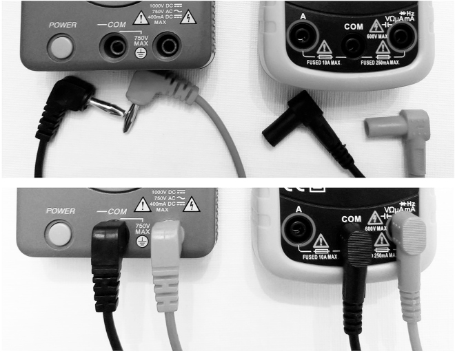
Figure 3-20: Connecting test leads to a multimeter. Meter with two inputs (left); meter with three inputs (right).
Your multimeter will provide a way to select whether you’re measuring voltage, current, or resistance. Let’s begin with voltage. Set your multimeter to measure voltage, DC. This may be indicated with V and the letters DC beside it, or you may see a series of dashes beside the V to indicate DC (versus a wavy line that indicates AC).
Once you have your multimeter set up to read DC voltage, measure the voltage across the resistor by touching one lead to the left side of the resistor (metal to metal) and the other lead to the right side. Keep in mind that voltage is always measured across two points, so it makes sense that we need to measure on both sides of the resistor. Since we are powering this circuit with a 9-volt battery, and the only circuit element present is the resistor, expect to measure approximately 9V. While you are measuring, you may notice that the value shown by the meter keeps changing a little (usually just the least significant digit, on the right). This is a result of the way digital meters work and does not mean your meter or your circuit is faulty.
Now try swapping the leads, putting the left lead on the right side of the resistor and vice versa. You should see the voltage value become negative (or positive if it was previously measuring negative). This is because the meter is measuring difference in potential and it treats the lead connected to COM as 0V; the measurement shown is the voltage difference at the other lead. In Figure 3-21, you can see the voltage measurement of my circuit—9.56V. That sounds about right since a new battery often has slightly higher voltage than advertised.

Figure 3-21: Measuring voltage
Next let’s measure the resistance of the resistor. First, disconnect your multimeter from the circuit to prevent accidental damage when you change the setting. Then set your multimeter to the resistance setting, which may be marked as Ω. With nothing connected, your multimeter is likely to show a 1 on the left or OL. This means that the resistance value is too large to display—the resistance of air is very high! Touch the multimeter leads together and the display should show zero. To measure the resistance of the resistor, you’ll want to disconnect it from the battery, but you can keep it attached to the breadboard if that is helpful. To ensure you see an accurate reading, avoid touching the circuit components and the metal of the leads while measuring; if you do, the resistance of your body may alter the value. You can see my resistance measurement in Figure 3-22; in my case the value was 9.88kΩ. The resistor I used had bands of brown, black, and orange (indicating 10,000Ω) followed by a gold band (indicating 5 percent tolerance), so this measurement looks good. That is, 9.88kΩ is within 5 percent of 10kΩ.
At this stage, you know the measured values for both voltage and resistance, so you can calculate the expected current using Ohm’s law—the current is voltage divided by resistance. For my circuit, that value will be 9.56V / 9,880Ω = 0.97mA. Before measuring the current in your circuit, perform that same calculation using your voltage and resistance measurements so you can see how much current you should expect to find flowing through your circuit.
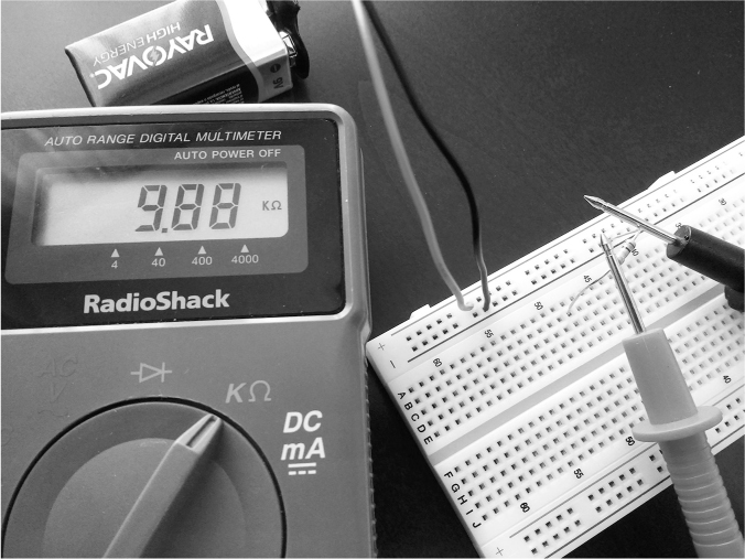
Figure 3-22: Measuring resistance
Now measure the current through your circuit and see how closely it matches your calculation. Measuring current is a bit different from measuring voltage or resistance. For the multimeter to be able to measure current, the current needs to flow through it. In other words, the meter must become part of the circuit, as illustrated in Figure 3-23.
Remember to disconnect your multimeter before you set it to measure DC current. The DC current symbols may be A or mA with DC or a series of dashes to indicate DC. Some meters have a single setting for measuring both DC and AC; in that case, the symbol may show both a straight line and a wavy line. Once your multimeter is on the correct setting, connect it to your circuit as shown in Figure 3-23.

Figure 3-23: How to connect a multimeter when measuring current
Hopefully your measurement came close to your calculation. As shown in Figure 3-24, my current measurement was 0.97mA, which is the same as my earlier calculation.
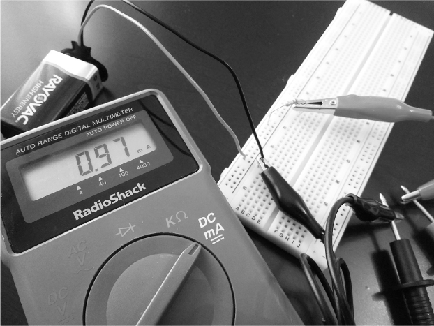
Figure 3-24: Measuring current. The right side of the resistor and the black wire from the battery don’t need to be connected to the breadboard.
If you’ve been following along to this point, then congratulations are in order! You’ve just built and measured an electrical circuit, or at the very least, you read about how I did it. And yet, you may feel a little underwhelmed. I understand. Honestly, aside from its excellent educational value, this circuit is a bit boring and useless! In the next project, let’s make something more interesting.
PROJECT #2: BUILD A SIMPLE LED CIRCUIT
Now it’s your turn to build an LED circuit and see it light up! Assuming you did the previous project, you can keep the 9-volt battery clip hooked up to your breadboard, but let’s swap out the 10kΩ resistor for a more appropriately sized resistor for this circuit. From our calculations earlier in this chapter in the section entitled “Light-Emitting Diodes” on page 42, we found that we want a 350Ω resistor to deliver 20mA of current. If I look in my big variety pack of resistors, I’m not likely to find a 350Ω resistor, and neither are you. The closest resistor you are likely to find is 330Ω.
Now we could use more than one resistor here to get to exactly 350Ω, but is that necessary? Is 330Ω close enough? Let’s find out. If we keep the 9-volt battery and still assume that we need to drop 7V across the resistor, then Ohm’s law tells us that the current through our circuit will now be I = V / R = 7V / 330Ω = 21.2mA. That will be just fine, since a typical red LED is rated for maximum current of about 25mA.
It’s worth pointing out that any LEDs you purchased may have different characteristics from what I’ve described. If your LED came with a data sheet, or if it has specs listed online, check the specs and do your own calculations: What’s the actual maximum or desired current for your specific LED? What’s the actual forward voltage for your specific LED? Note that this usually varies by LED color.
You need to know one more thing about LEDs before building your circuit. Unlike a resistor, where current can flow either way, the LED is designed to allow current flow in only one direction, so you need to know which end is which. The positive side (the anode) usually has a longer lead, and the negative side (the cathode) has a shorter lead, as shown in Figure 3-25. Current flows from positive to negative.
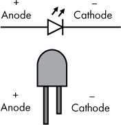
Figure 3-25: Identifying the anode and cathode on an LED
Once you have your numbers worked out and you know what value of resistor you want to use, connect things as follows, and as shown in the circuit diagram in Figure 3-26.
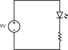
Figure 3-26: A simple LED circuit
Figure 3-27 is a photo of my LED, hooked up as described. Check out the glow! Hopefully your LED also lit up once the circuit was complete.

Figure 3-27: A glowing LED; attached battery not shown