5
MATH WITH DIGITAL CIRCUITS

In the previous chapter we covered logic gates and digital circuits, which enable us to implement logical expressions in hardware. Earlier in this book we defined computers as electronic devices that can be programmed to carry out a set of instructions. In this chapter, I begin to bridge those concepts by showing you how simple logic gates pave the way for the operations a computer executes. We cover a specific operation that all computers are able to perform–addition. First, we go over the basics of addition in binary. Then we use logic gates to build hardware that adds, demonstrating how simple gates work together in a computer to perform useful operations. Finally, we cover the representation of integers as signed and unsigned numbers in a computer.
Binary Addition
Let’s look at the basics of how addition works in binary. The underlying principles of addition are the same for all place-value systems, so you have a head start since you already know how to add in decimal! Rather than deal in abstract concepts, let’s take a concrete example: adding two specific 4-bit numbers, 0010 and 0011, as shown in Figure 5-1.

Figure 5-1: Adding two binary numbers
Just as we do in decimal, we begin with the rightmost place, known as the least significant bit, and add the two values together (Figure 5-2). Here, 0 + 1 is 1.

Figure 5-2: Adding the least significant bit of two binary numbers
Now let’s move one bit to the left and add those values together, as shown in Figure 5-3.

Figure 5-3: Adding the twos place
As you can see in Figure 5-3, this place requires us to add 1 + 1, which presents us with an interesting twist. In decimal, we represent 1 + 1 with the symbol 2, but in binary we only have two symbols, 0 and 1. In binary, 1 + 1 is 10 (see Chapter 1 for an explanation), which requires two bits to represent. We can only put one bit in this place, so 0 goes into the current place, and we carry the 1 to the next place, as indicated in Figure 5-3. We can now move to the next place (see Figure 5-4), and when we add these bits, we must include the carried bit from the previous place. This gives us 1 + 0 + 0 = 1.
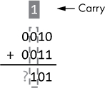
Figure 5-4: Adding the fours place
Finally, we add the most significant bit, as shown in Figure 5-5.

Figure 5-5: Adding the eights place
Once we add all the places, the complete result in binary is 0101. One way to sanity-check our work is to simply convert everything to decimal, as shown in Figure 5-6.

Figure 5-6: Adding two binary numbers, then converting to decimal
As you can see in Figure 5-6, our answer in binary (0101) matches what we’d expect in decimal (5). Simple enough!
Fortunately, addition works the same way no matter what base you’re working in. The only difference between bases is how many symbols are available to you. Binary makes addition particularly straightforward, since the addition of each place always results in exactly two output bits, each with only two possible values:
Output 1 A sum bit (S) of 0 or 1, representing the least significant bit of the result of the addition operation
Output 2 A carry-out bit (Cout) of 0 or 1
Half Adders
Now let’s say we want to construct a digital circuit that adds a single place of two binary numbers. We initially focus on the least significant bit. Adding the least significant bits of two numbers only requires two binary inputs (let’s call them A and B), and the binary outputs are a sum bit (S) and a carry-out bit (Cout). We call such a circuit a half adder. Figure 5-7 shows the symbol for a half adder.
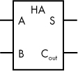
Figure 5-7: Symbol for a half adder
To clarify how the half adder fits in with our earlier example of adding two binary numbers, Figure 5-8 relates the two concepts.
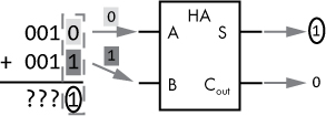
Figure 5-8: Half adder in action
As you can see in Figure 5-8, the least significant bit from the first number is input A and the least significant bit from the second number is input B. The sum is an output, S, and the carry-out is also an output.
Internally, the half adder can be implemented as a combinational logic circuit, so we can also describe it with a truth table, as shown in Table 5-1. Note that A and B are inputs, while S and Cout are outputs.
Table 5-1: Truth Table for a Half Adder
Inputs |
Outputs |
||
|---|---|---|---|
A |
B |
S |
Cout |
0 |
0 |
0 |
0 |
0 |
1 |
1 |
0 |
1 |
0 |
1 |
0 |
1 |
1 |
0 |
1 |
Let’s walk through the truth table in Table 5-1. Adding 0 and 0 results in 0 with no carry. Adding 0 and 1 (or the reverse) results in 1 with no carry. Adding 1 and 1 gives us 0 with a carry of 1.
Now, how do we go about implementing this with digital logic gates? The solution is straightforward if we examine one output at a time, as shown in Figure 5-9.
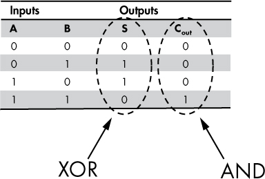
Figure 5-9: Truth table for a half adder; outputs match XOR, AND
Looking at only output S in Figure 5-9, we can see that it exactly matches the truth table for an XOR gate (see Chapter 4). Looking at Cout only, we can observe that it matches the output of an AND gate. Therefore, we can implement a half adder using only two gates: XOR and AND, as shown in Figure 5-10.

Figure 5-10: Half adder implemented with two logic gates, XOR and AND
As you can see in Figure 5-10, digital inputs A and B act as the inputs for both the XOR gate and the AND gate. The gates then produce the desired outputs, S and Cout.
NOTE
Please see Project #5 on page 89, where you can build a circuit for a half adder.
Full Adders
A half adder can handle the logic needed to perform addition for the least significant bits of two binary numbers. However, each subsequent bit requires an additional input: the carry-in bit, Cin. This is because every bit place, except the least significant bit, needs to handle the situation where addition of the previous bit place resulted in a carry-out, which in turn becomes the carry-in for the current bit place. Adding a Cin input to our adder component requires a new circuit design, and we call this circuit a full adder. The symbol for a full adder, shown in Figure 5-11, is similar to the symbol for a half adder, differing only by an extra input, Cin.

Figure 5-11: Symbol for a full adder
In Figure 5-12, we see an example of the relationship between binary addition of a single place and the full adder.

Figure 5-12: Full adder in action
The full adder handles the addition of a single place, including the carry-in bit. In the example shown in Figure 5-12, we add the bits in the 4s place. Since the bits in the previous place were 1 and 1, there’s a carry-in of 1. The full adder takes all three inputs (A = 0, B = 0, and Cin = 1) and produces an output of S = 1 and Cout = 0.
For a complete picture of the possible inputs and outputs of a full adder, we can use a truth table, shown in Table 5-2. This table has three inputs (A, B, Cin) and two outputs (S, Cout). Take a moment to consider the outputs from the various input combinations.
Table 5-2: Full Adder Truth Table
Inputs |
Outputs |
|||
|---|---|---|---|---|
A |
B |
Cin |
S |
Cout |
0 |
0 |
0 |
0 |
0 |
0 |
0 |
1 |
1 |
0 |
0 |
1 |
0 |
1 |
0 |
0 |
1 |
1 |
0 |
1 |
1 |
0 |
0 |
1 |
0 |
1 |
0 |
1 |
0 |
1 |
1 |
1 |
0 |
0 |
1 |
1 |
1 |
1 |
1 |
1 |
How do we go about implementing a full adder? As the name implies, a full adder can be realized by combining two half adders (Figure 5-13).
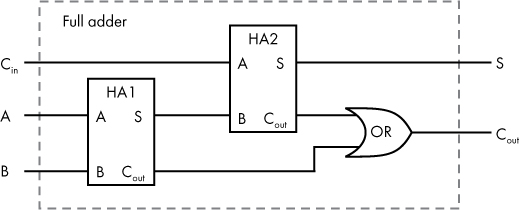
Figure 5-13: A full adder circuit realized with two half adders and an OR gate
A full adder’s sum output (S) should be the sum of A and B (which we can calculate using one half adder—HA1) plus Cin (which we can calculate with a second half adder—HA2), as shown in Figure 5-13.
We also need our full adder to output a carry-out bit. This turns out to be simple to implement, because the full adder’s Cout value is 1 if the carry-out from either half adder is 1. We can therefore use an OR gate to complete the full adder circuit, as shown in Figure 5-13.
Here we see another example of encapsulation. Once this circuit is constructed, the functionality of a full adder can be used without knowledge of the specific implementation details. In the next section, let’s see how we can use full and half adders together to add a number with multiple bits.
A 4-bit Adder
A full adder allows us to add two 1-bit numbers, plus a carry-in bit. This gives us a building block for creating a circuit that can add binary numbers with more than one place. Let’s now combine several 1-bit adder circuits to create a 4-bit adder. Let’s use a half adder for the least significant bit (since it doesn’t require a carry-in) and full adders for the other bits. The idea is to string the adders together so the carry-out from each adder flows into the carry-in of the subsequent adder, as shown in Figure 5-14.

Figure 5-14: A 4-bit adder
For consistency with the way people write numbers, I’ve arranged Figure 5-14 with the least significant bit on the right, and the diagram’s flow progressing from right to left. This means that our adder block diagrams will have inputs and outputs positioned differently than previously shown; don’t let that confuse you!
In Figure 5-15, I applied our earlier example of two (0010) plus three (0011) to this 4-bit adder.
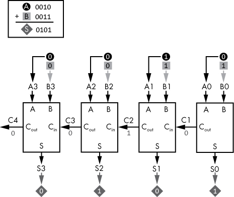
Figure 5-15: A 4-bit adder in action
In Figure 5-15, we can see how each bit from input A (0010) and input B (0011) is fed into each subsequent adder unit, starting with the least significant bit on the right, moving to the most significant bit on the left. You can follow the flow of the diagram by reading from right to left. Add the rightmost bits first, 0 (A0) and 1 (B0); the result is 1 (S0) with a carry of 0.
The output carry bit from the rightmost adder flows into the next adder as C1, where 1 (A1) and 1 (B1) are added, along with the carry of 0. This results in 0 (S1) with a carry of 1 (C2). The process continues until the leftmost adder completes. The final result is a set of the output bits, 0101 (S3 to S0), and a carry of 0 (C4). If we need to handle a larger number of bits, we can extend the design in Figure 5-15 by simply incorporating more full adders.
This type of adder requires the carry bits to propagate, or ripple, through the circuit. For this reason, we call this circuit a ripple carry adder. Each carry bit that ripples to the next full adder introduces a small delay, so extending the design to handle more bits makes the circuit slower. The output of the circuit will be inaccurate until all the carry bits have time to propagate.
Several versions of 4-bit adders are available in the 7400 series of ICs. If you need a 4-bit adder in a project, you can use such an IC rather than construct the adder from individual logic gates.
Let’s pause here and consider the broader implications of what we’ve just covered. Yes, you learned how to build a 4-bit adder, but how does this relate to computing? Recall that computers are electronic devices that can be programmed to carry out a set of logical instructions. Those instructions include mathematical operations, and we just saw how logic gates, built from transistors, can be combined to perform one of those operations—addition. We covered addition as a concrete example of a computer operation, and although we don’t go into the details in this book, you can also implement other fundamental computer operations with logic gates. This is how computers work—simple logic gates work together to perform complex tasks.
Signed Numbers
Thus far in this chapter we’ve only concerned ourselves with positive integers, but what if we want to be able to handle negative integers as well? First, we need to consider how a negative number can be represented in a digital system like a computer. As you know, all data in a computer is represented as sequences of 0s and 1s. A negative sign is neither a 0 nor a 1, so we need to adopt a convention for representing negative values in a digital system. In computing, a signed number is a sequence of bits that can be used to represent a negative or positive number, depending on the specific values of those bits.
A digital system’s design must define how many bits are used to represent an integer. Typically, we represent integers using 8, 16, 32, or 64 bits. One of those bits can be assigned to represent a negative sign. We can, for example, say that if the most significant bit is 0, then the number is positive, and if the most significant bit is 1, then the number is negative. The remaining bits are then used to represent the absolute value of the number. This approach is known as signed magnitude representation. This works, but it requires extra complexity in a system’s design to account for the bit that has a special meaning. For example, the adder circuits we built earlier would need to be modified to account for the sign bit.
A better way to represent negative numbers in a computer is known as two’s complement. In this context, the two’s complement of a number represents the negative of that number. The simplest way to find the two’s complement of a number is to replace every 1 with a 0 and every 0 with a 1 (in other words, flip the bits), and then add 1. Hang tight with me here; this is going to seem overly complicated at first, but if you follow the details, it will make sense.
Let’s take a 4-bit example, the number 5, or 0101 in binary. Figure 5-16 shows the process of finding the two’s complement of this number.
Figure 5-16: Finding the two’s complement of 0101
First, we flip the bits, then we add one, giving us 1011 binary. So, in this system, 5 is represented as 0101 and –5 is represented as 1011. Keep in mind that 1011 only represents –5 in the context of a 4-bit signed number. That binary sequence could be interpreted in other ways in a different context, as we will see later. What if we want to go the other way, starting with the negative value? The process is the same, as shown in Figure 5-17.
Figure 5-17: Finding the two’s complement of 1011
As you can see in Figure 5-17, taking the two’s complement of –5 gets us back to the original value of 5. This makes sense, given that the negative of –5 is 5.
Now we know how to represent a number as a positive value or a negative value using two’s complement, but how is this useful? I think the easiest way to see the benefits of this system is to just try it. Let’s say we want to add 7 and –3 (that is, subtract 3 from 7). We expect the result to be positive 4. Let’s first determine what our inputs are in binary, shown in Figure 5-18.

Figure 5-18: Find the 4-bit two’s complement form of 7 and –3.
Our two binary inputs will be 0111 and 1101. Now, forget for a moment that we’re dealing with positive and negative values. Just add the two binary numbers. Don’t worry about what the bits represent, just add them, and prepare to be amazed! Look at Figure 5-19 once you’ve done the binary math.
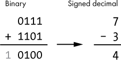
Figure 5-19: Addition of two binary numbers, interpreted as signed decimal
As you can see in Figure 5-19, this addition results in a carry-out bit beyond what a 4-bit number can represent. I’ll explain this in more detail later, but for now, we can ignore that carry-out bit. This gives us a 4-bit result of 0100, which is positive 4, our expected number! That’s the beauty of two’s complement notation. We don’t have to do anything special during the addition or subtraction operation; it just works.
Let’s pause here and reflect on the implications of this. Remember those adder circuits we built earlier? They will work for negative values too! Any circuit designed to handle binary addition can use the two’s complement as a means of handling negative numbers or subtraction. The detailed mathematical explanation for why all of this works is outside the scope of this book; if you are curious, there are good explanations available online.
Here’s another way to look at two’s complement notation: the most significant place has a weight equal to the negative value of that place, and all other places have weights equal to the positive values of those places. So, for a 4-bit number, the places have the weights shown in Figure 5-20.

Figure 5-20: Place-value weights of a signed 4-bit number using two’s complement notation
If we then apply this approach to the two’s complement representation of –3 (1101), we can calculate the decimal value as shown in Figure 5-21.
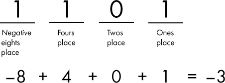
Figure 5-21: Find the signed decimal value of 1101 using two’s complement place value.
When dealing with two’s complement, I find that looking at the most significant place’s weight as equal to the negative value of that place is a convenient mental shortcut. Now that we have covered the weights of all the places in a 4-bit signed number, we can examine the full range of values that can be represented with such a number, as shown in Table 5-3.
Table 5-3: All Possible Values of a 4-bit Signed Number
Binary |
Signed decimal |
|---|---|
0000 |
0 |
0001 |
1 |
0010 |
2 |
0011 |
3 |
0100 |
4 |
0101 |
5 |
0110 |
6 |
0111 |
7 |
1000 |
–8 |
1001 |
–7 |
1010 |
–6 |
1011 |
–5 |
1100 |
–4 |
1101 |
–3 |
1110 |
–2 |
1111 |
–1 |
Given Table 5-3, we can observe that for a signed 4-bit number, our maximum value is 7 and our most negative value is –8, for a total of 16 possible values. Note that anytime the most significant bit is 1, the value will be negative. We can generalize as follows for an n-bit signed number:
- Maximum value: (2n–1) – 1
- Minimum value: –(2n–1)
- Count of unique values: 2n
So, for an 8-bit signed number (as an example), we find that
- Maximum value = 127
- Minimum value = –128
- Count of unique values = 256
Unsigned Numbers
Signed integers that use two’s complement to represent negative values are a convenient way to handle negatives without requiring specialized adder hardware. The adder we covered earlier works just as well with negative values as it does with positive values. However, there are scenarios in computing in which negative values simply aren’t needed, and treating our numbers as signed simply wastes about half the range of values (all the negative values go unused), while also capping the maximum possible value to about half of what could otherwise be represented. Because of this, in such scenarios we want to treat numbers as unsigned, meaning the sequence of bits always represents a positive value or zero, but never a negative value.
Looking again at a 4-bit number, Table 5-4 shows what each 4-bit binary value represents if we interpret it as signed or unsigned.
Table 5-4: All Possible Values of a 4-bit Number, Signed or Unsigned
Binary |
Signed decimal |
Unsigned decimal |
|---|---|---|
0000 |
0 |
0 |
0001 |
1 |
1 |
0010 |
2 |
2 |
0011 |
3 |
3 |
0100 |
4 |
4 |
0101 |
5 |
5 |
0110 |
6 |
6 |
0111 |
7 |
7 |
1000 |
–8 |
8 |
1001 |
–7 |
9 |
1010 |
–6 |
10 |
1011 |
–5 |
11 |
1100 |
–4 |
12 |
1101 |
–3 |
13 |
1110 |
–2 |
14 |
1111 |
–1 |
15 |
We can generalize as follows for an n-bit unsigned number:
- Maximum value: (2n) – 1
- Minimum value: 0
- Count of unique values: 2n
So, let’s take an example 4-bit value, say 1011. Looking at Table 5-4, what does it represent? Does it represent –5 or does it represent 11? The answer is “it depends!” It can represent either –5 or 11, depending on the context. From an adder circuit’s point of view, it doesn’t matter. As far as the adder is concerned, the 4-bit value is just 1011. Any addition operation is performed the same way regardless; the only difference is how we interpret the result. Let’s look at an example. In Figure 5-22, we add two binary numbers: 1011 and 0010.

Figure 5-22: Adding two binary numbers, interpreted as signed or unsigned
As you can see in Figure 5-22, adding those two binary numbers results in 1101, regardless of whether we’re working with signed or unsigned numbers. After the calculation is complete, we get to decide how to interpret that result. Either we just added –5 and 2 and the result was –3, or we added 11 and 2 and the result was 13. In either case the math works out; it’s just a matter of interpretation! In the context of computing, it is the program running on a computer that is responsible for correctly interpreting the result of an addition operation as signed or unsigned.
So far, we’ve mostly ignored the most significant carry-out bit, but it has a meaning that should be understood. For unsigned numbers, a carry-out of 1 means that an integer overflow has occurred. In other words, the result is too large to be represented by the number of bits assigned to represent an integer. For signed numbers, if the most significant carry-in bit is not equal to the most significant carry-out bit, then an overflow has occurred. Also for signed numbers, if the most significant carry-in is equal to the most significant carry-out, then no overflow has occurred, and the carry-out bit can be ignored.
Integer overflows are a source of errors in computer programs. If a program does not check if an overflow has occurred, then the result of an addition operation may be incorrectly interpreted, leading to unexpected behavior. A famous example of an integer overflow error is found in the arcade game Pac-Man. When the player reaches level 256, the right side of the screen is filled with garbled graphics. This happens because the level number is stored as an 8-bit unsigned integer, and adding 1 to its maximum value of 255 results in an overflow. The game’s logic doesn’t account for this condition, leading to the glitch.
Summary
In this chapter, we used addition as an example of how computers build upon logic gates to perform complex tasks. You learned how to perform addition in binary and how to construct hardware that can add binary numbers from logic gates. You saw how a half adder can add 2 bits and produce a sum and a carry-out bit, whereas a full adder can add 2 bits plus a carry-in bit. We covered how single-bit adders can be combined to perform multi-bit addition. You also learned how integers are represented in a computer using signed and unsigned numbers.
In the next chapter, we’ll move beyond combinational logic circuits and learn about sequential logic. With sequential logic, hardware can have memory, allowing for the storage and retrieval of data. You’ll see how memory circuits can be built. We’ll also cover clock signals, a method of synchronizing the state of multiple components in a computer system.
PROJECT #5: BUILD A HALF ADDER
In this project, you’ll construct a half adder using an XOR gate and an AND gate. The inputs will be controlled with switches or pushbuttons. The outputs should be connected to LEDs to easily observe their states. For this project, you’ll need the following components:
As a reminder, see the sections “Buying Electronic Components” on page 333 and “Powering Digital Circuits” on page 336 if you need help on those topics. For a reminder of how the pins are numbered on the 7408 IC, see Figure 4-14. The 7486 IC wasn’t covered previously, so I’m including its pinout diagram here in Figure 5-23.
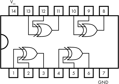
Figure 5-23: Pinout diagram for the 7486 XOR integrated circuit
Figure 5-24 provides the wiring diagram for a half adder. Keep reading past the figure for more details on how to build this circuit.

Figure 5-24: Half adder built from XOR and AND gates
Figure 5-24 shows the connections for switches, with pull-down resistors, and for LEDs, with current-limiting resistors. Also note the pin numbers on the 7486 and 7408 ICs, shown in boxes. Note the black dots found on the wires connecting A and B to the resistors and ICs. The dots represent a connection point—for example, switch A, the 470Ω resistor, pin 1 on the 7486 IC, and pin 4 on the 7408 IC are all connected. Don’t forget to connect the 7486 and 7408 ICs to 5V and ground via pins 14 and 7 (not shown in Figure 5-24), respectively.
Figure 5-25 shows how this circuit could look when implemented on a breadboard.

Figure 5-25: Half adder built from XOR and AND gates
Once you’ve constructed this circuit, try all combinations of inputs A and B to confirm that the outputs match the expected values as shown in the half adder truth table (Table 5-1).