


Troubleshooting
This chapter describes the steps that you can take to ascertain the health of the storage area network (SAN) fabric and perform problem determination when unplanned events occur. Although it provides many troubleshooting tips and techniques, it does not teach troubleshooting methodology.
This chapter provides the following information:
12.1 General problem determination
Troubleshooting should begin at the center of the SAN, which is the fabric. Because switches are located between the hosts and storage devices and have visibility into both sides of the storage network, starting with the fabric or fabrics can help narrow the search path. After eliminating the possibility of a fault within the fabric, determine whether the problem is on the storage side or the host side, and continue a more detailed diagnosis from there. Using this approach can quickly pinpoint and isolate problems.
For example, if a host cannot detect a storage device, determine whether the storage device is logically connected to the switch by using IBM Network Advisor to view the physical port status at the switch and the name server to determine whether the device is logically logged in to the fabric. If not, focus first on the switch directly connecting to storage. Use your vendor-supplied storage diagnostic tools to better understand why it is not visible to the switch. If the storage can be detected by the switch, and the host still cannot detect the storage device, then the problem is between the host and the switch.
12.2 Errors and symptoms
For problem determination of common problems and symptoms, the Fabric OS Troubleshooting and Diagnostics Guide provides information about identifying and working through them. It includes information about the following topics:
•LED statuses
•Connectivity
•Performance
•Fabric Merge and ISL
•FCIP and FCR problem determination
•Hardware problem determination
•Firmware upgrade problems
Each of the sections provides information about how to review and determine corrective action for some of the problems that might be encountered in the fabric.
The Fabric OS Troubleshooting and Diagnostics Guide is available for each major release of Fabric OS and can be obtained at the following website:
12.3 Switch and port status
It is important to understand the overall switch status for all switches in the fabric when you investigate problems within the storage area network. After you determine that the switches in the fabric are healthy and operational, you can do further investigation of port status to ensure that all relevant ports are healthy.
12.3.1 Displaying the switch status
Switch status is available in several locations in IBM Network Advisor. However, the product list provides a quick overview of all switches in a fabric and their present state by displaying icons.
Table 12-1 shows the status icons and their meanings.
Table 12-1 Status icons that are displayed in the product list of IBM Network Advisor
|
Icon
|
Status
|
|
No Icon
|
Healthy and Operational
|
|
|
Attention
|
|
|
Degraded or Marginal
|
|
|
Device Added
|
|
|
Device Removed or Missing
|
|
|
Down or Failed
|
|
|
Routed In
|
|
|
Routed Out
|
|
|
Unknown or Link Down
|
|
|
Unreachable
|
To display the product list, complete the following steps:
1. Log in to IBM Network Advisor with an ID with administrator privileges.
2. Click the SAN tab.
The product list is displayed in the right pane (see Figure 12-1).

Figure 12-1 IBM Network Advisor Product list
3. To display more details about a specific switch, right-click the switch in the right topology pane and select Properties from the menu.
The switch Properties window is displayed as shown in Figure 12-2.
|
Note: Use the switchStatusShow command in the CLI to display the overall status of the switch, including its power supplies, fans, and temperature. If the status of any one of these components is either marginal or down, the overall status of the switch is also displayed as marginal or down. If all components have a healthy status, the switch displays a healthy status. For more information about the switchStatusshow command, see the Fabric OS Troubleshooting and Diagnostics Guide, Fabric OS Administrator’s Guide and Fabric OS Command Reference that are available at the following website:
|

Figure 12-2 Switch Properties window
12.3.2 Port status
This section explains how to view port status.
Viewing the status of a port in IBM Network Advisor
Port status can also quickly be determined by expanding the product list. Each port has a corresponding icon to indicate its status. After a port has been identified as needing further investigation, you can obtain more information by using the displayed list.
The icons in Table 12-2 are displayed to indicate port status.
Table 12-2 Port status icons
|
Icon
|
Status
|
|
|
Occupied FC Port
|
|
|
Unoccupied FC Port
|
|
|
Attached FC Port
|
|
|
Trunk (port group)
|
|
|
IP and 10 GE Port
|
|
|
Attached IP and 10 GE Port
|
|
|
Attached-to-Cloud 10 GE Port
|
|
|
Virtual Port
|
|
|
Virtual FCoE Port
|
|
|
Attached FCoE Port
|
|
|
Pre-boot Virtual Port
|
|
|
Virtual Attached Port
|
|
|
Mirror Port
|
|
|
Bottleneck Port
|
To display the port statuses in the Product List in IBM Network Advisor, complete the following steps:
1. Open IBM Network Advisor and use an ID with admin privileges.
2. Click the SAN tab.
The product list is displayed in the left pane.
3. Click the + icon to expand the list of the fabric that contains the switch or switches.
4. Click the + icon next to the switch group that contains the switches for which the port statuses are to be displayed.
5. Click the + icon next to the switch or switches for which the port statuses are to be determined. A list of ports is displayed with the statuses.
Figure 12-3 shows the Product list expanded to view port statuses in IBM Network Advisor.

Figure 12-3 Port status
6. For more information about a specific port in the list, right-click the port and select Properties from the menu. The port Properties window is displayed (Figure 12-4).

Figure 12-4 Port Properties panel
Viewing the status of a port in the CLI
To view the status of a port, run the portShow [slot/] port command with admin permissions and specify the number that corresponds to the port you are troubleshooting. Example 12-1 shows the output of an example portShow command.
Example 12-1 Port status command in the CLI
ITSO_DCX8510-4:FID128:admin> portshow 1/4
portIndex: 4
portName: slot1 port4
portHealth: OFFLINE
Authentication: None
portDisableReason: None
portCFlags: 0x1
portFlags: 0x1 PRESENT U_PORT
LocalSwcFlags: 0x0
portType: 24.0
portState: 2 Offline
Protocol: FC
portPhys: 4 No_Light portScn: 2 Offline
port generation number: 8
state transition count: 1
portId: 010400
portIfId: 4312001b
portWwn: 20:04:00:05:33:96:f4:00
portWwn of device(s) connected:
Distance: normal
portSpeed: N16Gbps
FEC: Inactive
Credit Recovery: Inactive
LE domain: 0
Peer beacon: Off
FC Fastwrite: OFF
Interrupts: 0 Link_failure: 0 Frjt: 0
Unknown: 0 Loss_of_sync: 0 Fbsy: 0
Lli: 5 Loss_of_sig: 1
Proc_rqrd: 33 Protocol_err: 0
Timed_out: 0 Invalid_word: 371778
Rx_flushed: 0 Invalid_crc: 0
Tx_unavail: 0 Delim_err: 0
Free_buffer: 0 Address_err: 0
Overrun: 0 Lr_in: 0
Suspended: 0 Lr_out: 0
Parity_err: 0 Ols_in: 0
2_parity_err: 0 Ols_out: 0
CMI_bus_err: 0
ITSO_DCX8510-4:FID128:admin>
12.4 Port errors
After you understand the status of the port, the port error statistics also provide information about any physical or logical errors that are occurring on the link or links that are involved.
Port error statistics can be obtained in IBM Network Advisor or the command-line interface (CLI).
12.4.1 Viewing port statistics with IBM Network Advisor
Port error statistics are viewed with the Element manager in IBM Network Advisor. To display them, complete the following steps:
1. Log in to IBM Network Advisor with an ID that has admin privileges.
2. Click the SAN tab.
The product list and topology panes are displayed.
3. Right-click the switch for which port statistics are required in either the product list pane or the Topology pane, and select Element Manager → Ports. The port admin tab from Web Tools is displayed.
4. Select View → Advanced to change the panel options to advance mode and enable the port statistics tab.
5. Select the FC Ports tab to display the list of FC ports on that switch.
6. Select the port from the FC Ports Explorer pane and the general port properties tab is displayed in the right pane.
7. Select the Port Statistics tab and the port statistics are displayed for the selected port in the lower Port Statistics pane. Selecting either the Advanced tab or the Error Details tab in the Port Statistics pane provides error statistics on the ports (see Figure 12-5).

Figure 12-5 Port error statistics
12.4.2 Viewing the port statistics in the CLI
The portShow [slot/] port, as shown in Example 12-1 on page 305, displays port statistics in the lower half of the output.
The portstatsshow [slot/]port command provides more detailed output on the port statistics as shown in Example 12-2.
Example 12-2 Output of the portstatsshow [slot/]port command
ITSO_DCX8510-4:FID128:admin> portstatsshow 1/4
stat_wtx 2761009470 4-byte words transmitted
stat_wrx 1219327107 4-byte words received
stat_ftx 32748199 Frames transmitted
stat_frx 29806760 Frames received
stat_c2_frx 0 Class 2 frames received
stat_c3_frx 29806760 Class 3 frames received
stat_lc_rx 0 Link control frames received
stat_mc_rx 0 Multicast frames received
stat_mc_to 0 Multicast timeouts
stat_mc_tx 0 Multicast frames transmitted
tim_rdy_pri 0 Time R_RDY high priority
tim_txcrd_z 0 Time TX Credit Zero (2.5Us ticks)
tim_txcrd_z_vc 0- 3: 0 0 0 0
tim_txcrd_z_vc 4- 7: 0 0 0 0
tim_txcrd_z_vc 8-11: 0 0 0 0
tim_txcrd_z_vc 12-15: 0 0 0 0
tim_latency_vc 0- 3: 1 1 1 1
tim_latency_vc 4- 7: 1 1 1 1
tim_latency_vc 8-11: 1 1 1 1
tim_latency_vc 12-15: 1 1 1 1
fec_cor_detected 0 Count of blocks that were corrected by FEC
fec_uncor_detected 0 Count of blocks that were left uncorrected by FEC
er_enc_in 0 Encoding errors inside of frames
er_crc 0 Frames with CRC errors
er_trunc 0 Frames shorter than minimum
er_toolong 0 Frames longer than maximum
er_bad_eof 0 Frames with bad end-of-frame
er_enc_out 371778 Encoding error outside of frames
er_bad_os 343338 Invalid ordered set
er_pcs_blk 0 PCS block errors
er_rx_c3_timeout 0 Class 3 receive frames discarded due to timeout
er_tx_c3_timeout 0 Class 3 transmit frames discarded due to timeout
er_unroutable 0 Frames that are unroutable
er_unreachable 0 Frames with unreachable destination
er_other_discard 0 Other discards
er_type1_miss 0 frames with FTB type 1 miss
er_type2_miss 0 frames with FTB type 2 miss
er_type6_miss 0 frames with FTB type 6 miss
er_zone_miss 0 frames with hard zoning miss
er_lun_zone_miss 0 frames with LUN zoning miss
er_crc_good_eof 0 Crc error with good eof
er_inv_arb 0 Invalid ARB
er_single_credit_loss 0 Single vcrdy/frame loss on link
er_multi_credit_loss 0 Multiple vcrdy/frame loss on link
phy_stats_clear_ts 0 Timestamp of phy_port stats clear
lgc_stats_clear_ts 0 Timestamp of lgc_port stats clear
ITSO_DCX8510-4:FID128:admin>
The porterrshow CLI command provides an overview of port statistics for the entire switch.
12.4.3 Resetting the port error statistic counters
When errors are reported on a link, it is important to understand that the error count is cumulative. There is no indication in these counters as to when the errors occurred.
In order to prove that the errors are relevant and still occurring, clear the error statistic counters and recheck them after some time passes. That is, a single snapshot does not provide enough information to determine whether the error is still occurring. For example, check at 5- and 60-minute intervals.
To reset all port statistics counters to zero on a selected device or fabric, complete the following steps:
1. Right-click a device or a fabric on the Connectivity Map or Product List and select Monitor → Performance → Clear Counters. An attention message is displayed.
2. Click Yes on the message.
All the port statistics counters and port logs will be cleared on all reachable switches in that switch group. The audit events log generated by the switches is displayed in the Master Log.
12.4.4 Understanding error counters
Based on the errors that occur, some generalizations can be made for further investigation. Table 12-3 lists port error counters, what the error is counting, and suggestions for further investigation.
Table 12-3 Error summary description
|
Error type
|
Description
|
|
frames tx
|
Frames transmitted.
|
|
frames rx
|
Frames received.
|
|
enc in
|
Encoding errors inside frames.
|
|
crc err
|
Frames with CRC errors.
|
|
crc g_eof
|
CRC errors that occur on frames with good end-of-frame delimiters.
|
|
too shrt
|
Frames shorter than minimum.
|
|
too long
|
Frames longer than maximum.
|
|
bad eof
|
Frames with bad end-of-frame delimiters.
|
|
enc out
|
Encoding error outside of frames.
|
|
disc c3
|
Number of Class 3 frames discarded (Rx). This counter includes the sum of the following Class 3 discard counters that are reported by the portStatsShow command: er_rx_c3_timeout, er_tx_c2_timeout, er_c2_dest_unreach, and er_other_disc.
For a description of these counters, run portStatsShow help.
|
|
link fail
|
Link failures (LF1 or LF2 states).
|
|
loss sync
|
Loss of synchronization.
|
|
loss sig
|
Loss of signal.
|
|
frjt
|
Frames rejected with F_RJT.
|
|
fbsy
|
Frames busied with F_BSY.
|
Here are tips for further investigation of errors:
•crc_err and enc_out errors together imply a small form-factor pluggable (SFP) issue.
•enc_out errors on their own imply a cable/connector issue. This error can cause a performance problem because of buffer recovery.
•too_long or too_short errors indicate an unreliable link.
•disc_c3 relates to port congestion.
•loss_sig can indicate incompatible speeds between two points. These error messages can also be caused by severe physical layer errors or by devices that are being reset, such as server reboots.
12.4.5 SFP and optic levels
To complete the review of port health, complete the following steps to check the SFP status and optic levels:
1. Log in to IBM Network Advisor with an account that has admin privileges.
2. Select the SAN tab.
The Product List and Topologies panes are displayed.
3. In the Product List, highlight the switch for which SFP and optic levels are required and select Monitor → Port Optics (SFP).
The Port Optics (SFP) window is displayed as shown in Figure 12-6.

Figure 12-6 Port Optics (SFP) window
The Port Optics (SFP) window contains the SFP information and optic readings for all switches in the port.
12.5 System messages and RAS logs
This section describes the types of system messages and what to do with them.
12.5.1 System message types
FOS supports three types of system messages. A system message can be of one or more of the following types:
•RASLog messages
•Audit log messages
•First Failure Data Capture messages
12.5.2 RASLog messages
RASLog messages report significant system events (failure, error, or critical conditions) or information, and are also used to show the status of the high-level user-initiated actions. RASLog messages are forwarded to the console, to the configured syslog servers, and to the Simple Network Management Protocol (SNMP) management station through SNMP traps or informs.
The errDump command shows the error log without pagination, and the errShow command shows the error log messages with pagination.
The system messages are documented in the Fabric OS Message Reference guide, which helps you diagnose and fix problems. You can find this guide at the following website:
The messages are organized alphabetically by module name. A module is a subsystem in the Fabric Operating System (FOS). Each module generates a set of numbered messages. For each message, the guide provides message text, probable cause, recommended action, and severity level. There might be more than one cause and more than one recommended action for any specific message, but the guide describes the most probable cause and typical action that is recommended.
12.5.3 Audit log messages
Event auditing is designed to support post-event audits and problem determination. It is based on high-frequency events of certain types, such as security violations, zoning configuration changes, firmware downloads, and certain types of fabric events. Audit messages that are flagged as AUDIT are not saved in the switch error logs. The switch can be configured to stream audit messages to the switch console and to forward the messages to specified syslog servers. The audit log messages are not forwarded to an SNMP management station. There is no limit to the number of audit events.
12.5.4 First-Failure data capture messages
First-Failure data capture (FFDC) is used to capture failure-specific data when a problem or failure is noted for the first time and before the switch reboots or trace and log buffers are wrapped. All subsequent iterations of the same error are ignored. This critical debug information is saved in nonvolatile storage and can be retrieved by running supportSave. The FFDC data is used for debugging or analyzing the problem. FFDC is intended for use by Brocade technical support.
12.6 SAN health
Brocade SAN Health is a no-charge software utility that is designed to securely audit and analyze your SAN environment. To help optimize your SAN’s performance, SAN Health automatically discovers critical fabric characteristics and reports their details in easy-to-understand Excel and Visio formats. In addition, SAN Health performs critical tasks, such as the following ones:
•Taking inventory of devices, switches, firmware versions, and fabrics
•Capturing and displaying historical performance data
•Comparing zoning and switch configurations against preferred practices
•Assessing performance statistics and error conditions
•Producing detailed graphical reports and diagrams
SAN Health gives you a powerful tool that helps you focus on optimizing your SAN rather than manually tracking its components. In fact, a wide variety of useful features make it easier for you to collect data, identify potential issues, and check your results over time.
To provide a comprehensive report about your SAN environment, SAN Health uses two main components:
•Data capture application
•Back-end report processing engine
After SAN Health finishes the capture of switch diagnostic data, the back-end reporting process automatically generates a Visio topology diagram and a detailed snapshot report of your SAN configuration. This summary report contains information about the entire SAN and specific details about fabrics, switches, and individual ports. Other useful items in the report include alerts, historical performance graphs, and preferred practices. SAN Health delivers topology diagrams, comprehensive reports, detailed explanations, and more.
It is important to note that the SAN health report is a snapshot, so reflects only the condition of the fabric at that specific point. In complex or busy environments, statuses can change quickly, so the SAN health report should be used as a reference and confirmed with real-time investigation.
12.6.1 Installing Brocade SAN Health
To install Brocade SAN Health, complete the following steps:
1. Go to the following link and download SAN Health Diagnostics Capture:
http://www.brocade.com/en/support/support-tools/support-download-san-health-diagnostics-capture.html
2. Download, extract, and install the application with the default settings.
12.6.2 Using SAN Health Diagnostics Capture
To run the application to collect and upload the fabric information for report generation, complete the following steps:
1. Launch the SAN Health collection tool from the desktop icon or Start menu option on MS Windows based systems. The SAN Health application window will be displayed (see Figure 12-7 on page 313).
2. Click the New button at upper left of the SAN Health application window.
3. Select the Site Details tab and complete the fields. These details are used on the title page of the reports. The report is processed at Brocade and is returned by using a secure single sign-on web page. An ID is automatically created from the site details if one does not already exist.
4. Click the Add Switches tab and add or confirm switch IPs and log-in credentials.
5. Click the Fabric tab, select the fabric or fabrics in the tree view to provide a name for each fabric, and then select the performance capture duration from the pull-down menu.
6. Click Test Fabric Connectivity Get Switch Details to ensure that all switches can communicate with the SAN Health Application.
7. Click the Save button on the top task bar to save the configuration for future use.
8. Click the Capture tab and click Start Audit. Before the audit starts, a set of “pre-flight” checks are run to ensure that the data values have been entered correctly. Any items reported as incorrectly entered must be corrected before the application allows an audit to start.
When the audit begins, processing time depends on the capture performance data interval that is set on the Fabric tab. The progress of the tool as it completes the audit is displayed in left pane of the window.
Figure 12-7 shows the SAN Health application window with the Site Details tab selected.

Figure 12-7 SAN Health application with the Site Details tab selected
9. To receive the report, the encrypted SAN Health file (.BSH) file must be sent to the Brocade report generator. You have three options to complete this task:
– Click Send the diagnostics data file via HTTPS.
– Upload the file at https://my.brocade.com/upload/ReportGeneration.jsp.
– Send the file as an email attachment to mailto:[email protected].
10. A report generation notification email is sent from the Brocade SAN Health Administrator when the report is available for download at the MyBrocade portal. The report contains a spreadsheet, a Visio file, and SHData files. This last file can be loaded by SAN Health Professional to do advanced analysis.
12.6.3 SAN Health Professional
Brocade SAN Health Professional provides an easy-to-understand framework for analyzing SAN components and configuration data that is captured by the SAN Health Diagnostics Capture utility. It provides a straightforward, easy-to-navigate user interface for auditing SAN Health data captures, making it a valuable tool for SAN inventory tracking and change management activities. You can import up to two SAN Health Diagnostic Capture captures to SAN Health Professional for immediate, detailed analysis about any SAN component.
In addition to its standard data analysis and search capabilities, the SAN Health Professional framework supports optional add-on modules.
SAN Health Professional provides a straightforward, easy-to-navigate user interface for auditing SAN Health data captures, making it a valuable tool for inventory tracking and change management activities. Organizations can import up to two SAN Health captures to SAN Health Professional for immediate, detailed analysis about any component.
To enable the highest level of flexibility, SAN Health Professional provides extensive searching and filtering capabilities. Searches can be broad (for example, a single search string such as “HBA” or “CHIPID”) or precise. Precision searching narrows the search to any combination of attribute names, devices, ports, switches, directors, fabrics, aliases, zones, or configurations.
For more information about SAN Health Professional, including package download and installation instructions, see the Brocade SAN Health website:
12.7 Collecting support data
The following sections detail some of the diagnostic features that can gather relevant support information.
The supportShow CLI command can be run on the switch to dump important diagnostic and status information to the session window for review and capture. Most Telnet and SSH clients offer the ability to capture session data before opening the session. IBM Network Advisor and CLI (use the supportsave CLI command) allow administrators to collect a supportsave. The supportsave command collects a number of important outputs in a series of files and compresses them into a package. This package can then be sent to the service provider for support and problem determination. The supportsave data package is preferred by most support providers.
12.7.1 Saving comprehensive diagnostic files to the server
To save comprehensive diagnostic files to the server, connect to the switch, log in as the admin user, run supportSave -c, and respond to the prompts. The -c flag uses the FTP, SCP, or SFTP parameters that are saved by the supportFtp command. If this flag is omitted, the FTP, SCP, or SFTP parameters must be specified through command-line options or interactively. To display the current supportFTP parameters, run supportFtp. On a dual-CP system, run supportFtp on the active CP.
12.7.2 Scheduling technical support and event information collection by using IBM Network Advisor
Technical support and event information can be collected for up to 50 devices. Technical SupportSave uses the built-in FTP, SCP, or SFTP server that is configured on the Management server to save data.
To capture technical support and event information at a predetermined date and time, complete the following steps:
1. Click Monitor → Technical Support → Product/Host SupportSave. The Technical SupportSave window opens.
2. Click the Schedule tab.
3. Select Enable scheduled Technical Support Data.
4. Select how often the scheduled collection will occur from the Frequency list.
5. Select the start date for the scheduled collection from the Start Date list. This list is only available when Weekly or Monthly is selected from the Frequency list.
6. Select the time that the scheduled collection will begin from the Start Time Hour and Minute lists.
7. Click the SAN Products tab, if necessary, and complete the following steps:
a. Right-click in the Available SAN Products table and select Expand All.
b. Select the switches to collect data for in the Available SAN Products table, and click the right arrow to move them to the Selected Products and Hosts table.
The Available SAN Products table displays the following information:
– All Levels: All discovered devices and ports as both text and icons.
– Name: The name of the available switch.
– Product Type: The type of product.
– Tag: The tag number of the device.
– Serial #: The serial number of the device.
– WWN: The switch port’s worldwide name.
– IP Address: The switch port’s IP address.
– Domain ID: The switch port’s top-level addressing hierarchy of the domain.
– Vendor: The hardware vendor’s name.
– Model: The name and model number of the hardware.
– Port Count: The total number of ports.
– Firmware: The firmware version.
– Location: The customer site location.
– Contact: The primary contact at the customer site.
– Description: A description of the customer site.
– State: The switch state, for example, online or offline.
– Status: The operational status of the switch, for example, unknown or marginal.
8. Click the Hosts tab and complete the following steps:
a. Right-click in the Available SAN Products table and select Expand All.
b. Select the products to collect data for in the Available Hosts table and click the right arrow to move them to the Selected Products and Hosts table. The Selected Products and Hosts table displays the following information:
• IP Address: The IP address of the selected product or host.
• Name: The name of the selected product or host.
• WWN: The worldwide name of the selected product or host.
• Firmware Type: The type of firmware: FOS (Fabric OS).
• Firmware version: The firmware version of the selected product or host.
• Support Save Credentials: Whether the product or host has SupportSave credentials or not.
The Available Hosts table displays the following information:
– Name: The name of the available host.
– IP Address: The host port’s IP address.
– Network Address: The network address of the host.
– Fabrics: The fabric of the host.
9. Select how often to purge the support data from the Purge Support Data list.
10. Click OK on the Technical SupportSave window.
12.7.3 Starting immediate technical support information collection
To capture technical support and event information for specified devices, complete the following steps:
1. Click Monitor → Technical Support → Product/Host SupportSave. The Technical SupportSave window is displayed.
2. Click the Generate Now tab, if necessary.
3. Click the SAN Products tab, if necessary, and complete the following steps:
a. Right-click in the Available SAN Products table and select Expand All.
b. Select the switches to collect data from in the Available SAN Products table and click the right arrow to move them to the Selected Products and Hosts table. Technical SupportSave data for Fabric OS devices is saved to the following directory:
Install_Homedataftproot echnicalsupport
4. Click the Hosts tab, if necessary, and complete the following steps:
a. Right-click in the Available Hosts table and select Expand All.
b. Select the hosts to collect data from in the Available Hosts table and click the right arrow to move them to the Selected Products and Hosts table.
5. Click OK on the Technical SupportSave window. The Technical SupportSave Status window opens with the following details:
– Name: The name of the product.
– IP Address: The product’s IP address.
– Firmware Type: The type of product.
– Progress: The status of the supportsave collection. On products that are running FOS V7.0 or later, this field shows the percentage complete and is updated every minute. For Host products, and FOS products that are running Version 6.4 or earlier, this field cannot display the percentage (it only displays whether it is “In Progress” or “Completed”).
– Status: The status of the supportsave process, for example, Success or Failure.
6. Click Close on the Technical SupportSave Status window.
12.8 Using MAPS for problem determination
Monitoring and Alerting Policy Suite (MAPS) as described in “Flow Vision” on page 192 provides a number of tools that can be used for problem determination and monitoring.
Because MAPS can be used to monitor and report on port health, back-end health, and field-replaceable unit (FRU) health, it is an excellent tool to review data if problems occur in the fabric.
The following sections describe some of these features from a problem determination perspective.
|
More documentation:
The Monitoring and Alerting Policy Suite Administrator’s Guide provides detailed instructions for configuring and monitoring all aspects of MAPS by using the CLI.
Detailed instructions for using MAPS with the graphical user interface are provided in the Brocade Network Advisor SAN User Manual.
You can download these publications at the following website:
|
12.8.1 Port health and cyclic redundancy checks monitoring
The Port Health category monitors port statistics and takes action based on the configured thresholds and actions. Thresholds can be configured per port type and optionally applied to all ports of the specified type. Ports whose thresholds can be monitored include physical ports, D_Ports, E_Ports, F_Ports, and Virtual E_Ports. The Port Health category also monitors the physical aspects of an SFP transceiver, such as voltage, current, receive power (RXP), transmit power (TXP), and state changes in physical ports, D_Ports, E_Ports, and F_Ports.
|
Note: For detailed information and instructions on configuring, creating, and editing thresholds and actions, see the Monitoring and Alerting Policy Suite Administrator’s Guide, which is available at:
|
Cyclic redundancy checks (CRCs) serve to validate the integrity of a frame. When validation fails, the frame that arrived at the receiving port is corrupted. Frame corruption can be caused by device disconnection, an optical transceiver failure at the device, fiber optic cabling, or a poor connection.
Two types of CRC errors can be logged on a switch. Taken together, they can help determine which link introduced the error into the fabric. The two types are plain CRCs, which have bad end-of-frame (EOF) markers, and CRCs with good EOF (crc g_eof) markers. When a crc g_eof error is detected on a port, it indicates that the transmitter or path from the sending side might be a possible source. When a complete frame that contains a CRC error is first detected, the error is logged, and the good EOF (EOFn) is replaced with a bad EOF marker (EOFni). Because Brocade switches forward all packets to their endpoints, changing the EOF marker allows the packet to continue but not be counted.
For MAPS threshold and fencing purposes, only frames with CRC errors and good end-of-frame markers are counted. This process enables you to know exactly how many errors were originated in a specific link.
You can use the MAPS dashboard to display an overview of port health and then investigate it further in more detail.
To display port health, complete the following steps:
1. Open IBM Network Advisor with an ID that has admin privileges.
2. Click the Dashboard tab to display the dashboard as shown in Figure 12-8.

Figure 12-8 MAPS Dashboard
3. To display the port health metrics, select the Dashboard pull-out and the available dashboards are displayed.
4. Click the + to expand the default dashboards available and select SAN Port Health (see Figure 12-9 on page 318).
5. Select the Scope pull-down menu to alter the time span over which the default metrics are reported from in the display in the lower right pane.
Figure 12-9 shows MAPS Dashboard with SAN Port health selected.

Figure 12-9 MAPS Dashboard with SAN Port Health selected
6. Scroll to view the CRCs reported for both inter-switch link (ISL) and fabric ports for the time frame that is selected.
7. Use the Top Initiator Ports CRC Errors, Top ISL Ports CRC Errors, and Top Target Ports CRC errors widgets to view all relevant CRC errors.
Figure 12-10 shows an example of the Top ISL Ports CRC Errors widget.

Figure 12-10 TOP ISL Ports CRC Errors widget
When you use this method, ports that encounter CRC errors can quickly be discovered and corrected.
12.8.2 Back-end port monitoring
Back-end ports can be connected to ports within a fixed-port switch or to other blades within the switch chassis. Therefore, their functionality is different from front-end ports, which connect to devices outside of the switch. The primary task of back-end ports is to route packets that pass through a switch’s ASICs. Switch (and consequently fabric) performance degrades when there are errors in back-end ports. MAPS error notification allows for earlier corrective action.
MAPS monitors the back-end port counter statistics for back-end ports through the group ALL_BE_PORTS, which identifies each port by using a slot-port combination such as 3/3/1. For fixed-port switches, the slot number is 0. Worldwide name (WWN) IDs and Port Names are not supported. The predefined groups for front-end ports do not apply to back-end ports. History data for back-end ports is collected for seven days.
The Back-end health category in the MAPS widget “Out of Range Violations” enables monitoring of the health of the back-end switch ports for these errors:
•CRC and Link reset error rates
•Invalid transmission words
•BAD_OS
•Frame length (either too long or truncated)
Figure 12-11 shows the Back-end port monitor in the MAPS Out of Range Violations widget that is available in the IBM Network Advisor dashboard.

Figure 12-11 Back-end Port monitor
To display the Back-end Port Health monitor, complete the following steps:
1. Open IBM Network Advisor with an ID that has admin privileges.
2. Click the Dashboard tab and the dashboard is displayed.
3. To display the back-end port health metrics, select the Dashboard pull-out and the available dashboards are displayed.
4. Click the + to expand the default dashboards available and select Product Status and Traffic (see Figure 12-9 on page 318).
5. Select the Scope pull-down menu to alter the time span over which the default metrics are reported from in the display in the lower right pane.
6. Scroll to view the Out of Range Violations widget.
7. If any violations are reported, right-click the row and select Violations to display the Back-end Port Violation window. More information about the parameter that is out of range is displayed in the lower pane.
The window displays a number of valuable information columns, including the device that reported the violation, the time the violation occurred, the metric that was out of range, and the recommended action.
12.8.3 FRU Health
The FRU Health category enables rules to be defined for FRUs. The following table lists the monitored parameters in this category. Possible states for all FRU measures are faulty, inserted, on, off, and out.
Table 12-4 shows a list of supported FRU Health category parameters.
Table 12-4 FRU Health category parameters
|
Monitored parameter
|
Description
|
|
Power supplies (PS_STATE)
|
State of a power supply has changed.
|
|
Fans (FAN_STATE)
|
State of a fan has changed.
|
|
Blades (BLADE_STATE)
|
State of a slot has changed.
|
|
SFPs (SFP_STATE)
|
State of the SFP transceiver has changed.
|
|
WWN (WWN_STATE)
|
State of a WWN card has changed.
|
The FRU Health category is reported in the MAPS Out of Range Violations widget available in the IBM Network Advisor dashboard.
To open the widget, complete the following steps:
1. Open IBM Network Advisor with an ID with that has admin privileges.
2. Click the Dashboard tab to display the dashboard.
3. To display the FRU Health metrics, select the Dashboard pull-out, which displays the available dashboards.
4. Click the + to expand the default dashboards that are available and select the Product Status and Traffic menu option (see Figure 12-9 on page 318).
5. Select the Scope pull-down menu to alter the time span over which the default metrics are reported from in the display in the lower right pane.
6. Scroll to view the Out of Range Violations widget.
7. If any violations are reported, right-click the row and select Violations to display the FRU Health Violation panel.
More information about the parameter that is out of range is displayed in the lower pane (see Figure 12-12).

Figure 12-12 FRU Health Violations panel
12.8.4 Fibre Channel over IP (FCIP) Health
The FCIP Health category enables definition of rules for FCIP health, including circuit state changes, circuit state utilization, and packet loss. The FCIP monitors support Minute, Hour, Day, and Week time bases for these parameters:
•Tunnel state change
•Tunnel throughput
•Tunnel QoS throughput
•Tunnel QoS Packet loss
•FCIP Circuit State Changes
•FCIP Circuit Utilization
•FCIP Packet loss
•FCIP Circuit Round Trip Time
•FCIP connection variance
The three default monitoring policies (Aggressive, Moderate, and Conservative) have preconfigured thresholds for FCIP criteria for MAPS monitoring. Each default policy has actions that are triggered when the reported value is greater than the threshold value.
|
Note: Additional FCIP parameters are monitored on the IBM SAN42B-R extension switch. In addition to the monitors that are available in the default policies, the following things are also monitored:
•FCIP tunnel state change (STATE_CHG): The number of FCIP tunnel state changes. This count applies to the tunnel group only.
•FCIP tunnel or tunnel QoS utilization (UTIL): The percentage of FCIP utilization. This this monitoring applies to both the tunnel and the tunnel QoS groups.
For more information about FCIP categories and monitoring, see the Monitoring and Alerting Policy Suite Administrator’s Guide that is available at the following website:
|
To view FCIP Health, complete the following steps:
1. Open IBM Network Advisor with an ID that has admin privileges.
2. Click the Dashboard tab to display the dashboard.
3. To display the FCIP Health metrics, select the Dashboard pull-out and the available dashboards are displayed.
4. Click the + icon to expand the default dashboards available and select Product Status and Traffic (see Figure 12-9 on page 318).
5. Select the Scope pull-down menu to change the time span over which the default metrics are reported from in the display in the lower right pane.
6. Scroll to view the Out of Range Violations widget.
7. If any violations are reported, right-click the row and select Violations to display the FCIP Health Violation window. More information about the parameter that is out of range is displayed in the lower pane.
12.9 Flow Vision
Flow Vision (described in Chapter 7, “Fabric Vision” on page 191) provides a number of tools that can be employed for troubleshooting both before implementation or during unplanned events. Flow vision is divided into three categories: Flow Monitor, Flow Generator, and Flow Mirror. These categories will be reviewed in the following sections as they pertain to troubleshooting.
The statistics that are generated by using Flow Vision can also be monitored with the Monitoring and Alerting Policy Suite (MAPS) threshold service that makes the two features a powerful diagnostics and monitoring tool when they are used together.
|
Note: For more information about the Flow Vision tool, see the Flow Vision Administrator’s Guide, which is available at the following website:
|
12.9.1 Flow Monitor
A common use of flow monitors is to monitor traffic that is flowing from a particular ingress port to a specified target egress port. Monitoring of various frame types at a switch port can provide insights into storage I/O access patterns at a LUN, reservation conflicts, and I/O errors. Examples of the frame types that can be monitored include SCSI Aborts, SCSI Read, SCSI Write, SCSI Reserve, and all rejected frames.
When a problem is discovered in a flow either by MAPS threshold monitoring of preconfigured flows or a Flow has been defined for the path that is to be investigated, the Flow Monitoring window can be displayed to view detailed information about that flow. See “Flow Vision” on page 19 for more information about configuring flows.
To view the summary data for a Flow Monitor flow, complete the following steps:
1. Select the device on which a defined flow has been configured and select Monitor → Fabric Vision → Flow Monitor The Flow Vision window is displayed pre-populated with a list of all defined flows in the Flow Definitions table (see Figure 12-13).
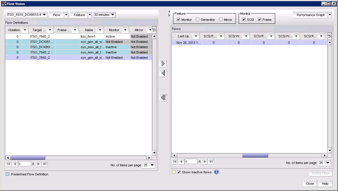
Figure 12-13 Flow Vision monitor panel
2. Select a time interval for monitoring the flow in the Time duration list.Possible values are 30 minutes, 1 hour, 6 hours, 12 hours, 1 day, 3 days, 1 week, and 1 month.
3. Select the flow to be monitor in the Flow Definitions table.
4. Click the right arrow button to display the selected flow in the Flows table.
5. Select or clear the SCSI check box to display or hide SCSI-related measures.
SCSI-related measures include SCSI read count, write count, read rate, write rate, read data, write data, and read and write frame data.
6. Select or clear the Frame check box to display or hide frame-related measures.
Frame-related measures include transmit (Tx) and receive (Rx) frame count, Transmit frame and receive frame rate, Transmit and receive word count, and transmit and receive throughput.
7. The subflow data for the selected Flow Monitor flow is displayed for review.
Data updates dynamically every 5 minutes.
|
Note: Many metrics are available. However, all of them might not display, depending on the configured flow. For descriptions of Flow Monitor review and the metrics that are available, see the Flow Vision Administrator’s Guide that is available at the following website:
|
12.9.2 Flow Generator
Flow Generator is a test traffic generator for pre-testing the SAN infrastructure (including internal connections) for robustness before deploying it.
The configuration of Flow Generator and flow monitor is described in the Flow Vision Administrator’s Guide which is available at the following website:
Flow Generator flows can be monitored by using Flow Monitor. For example, a combination of Flow Generator flows and Flow Monitor flows can be used to verify per-flow throughput at an ingress or egress port. This feature can be useful when more than one Flow Generator flow share an ingress or egress port. To do this, a flow must be created using both the Flow Generator and Flow Monitor features that share the ingress or egress port. In this manner, a link can be tested before implementation.
12.9.3 Flow Mirroring
Flow Mirror duplicates the specified frames in a user-defined flow and sends them to the switch CPU or sends them to a mirror port.
|
Note: Only 64 bytes of the FC frame is captured when mirrored to the switch CPU.
|
In this manner, Flow Mirror can assist with diagnosing a number of symptoms and implementing an analyzer without interruption to the link.
Here are examples of problems that can be investigated with Flow Mirror:
•Diagnosing excessive SCSI reserve and release activity
•Diagnosing a slow-draining F_Port
•Tracking SCSI commands
•Tracking latency between a host and all connected targets
•Troubleshooting protocol errors
For more information about how to create a Flow Mirror port, and detailed use cases and examples, see the SAN User Manual and Flow Vision Administrator’s Guide that is available at the following website:
..................Content has been hidden....................
You can't read the all page of ebook, please click here login for view all page.