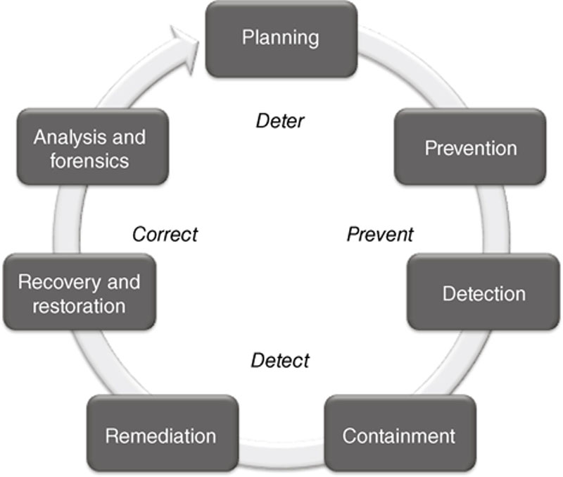
Risk and Vulnerability Assessments
Abstract
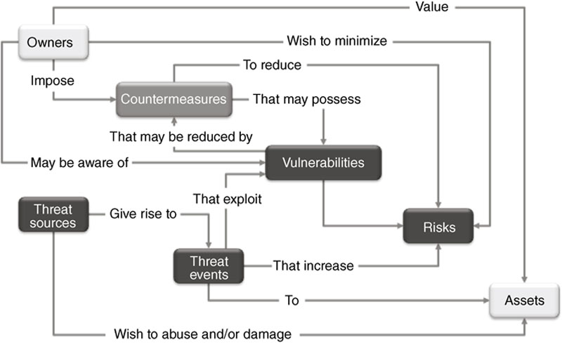
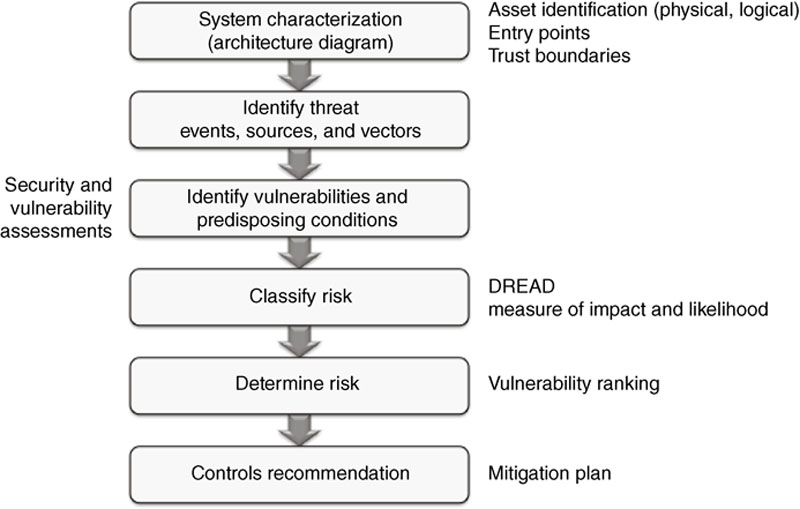
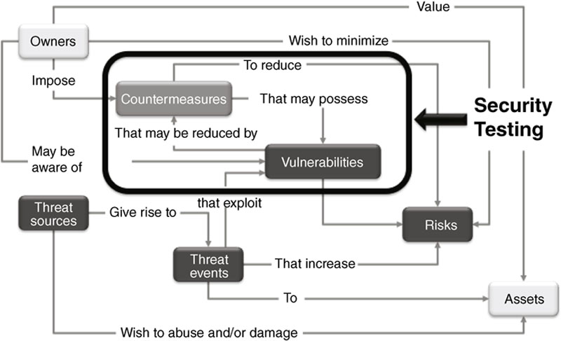
Risk management involves an understanding of threats, vulnerabilities and consequences. To effectively manage risk, therefore, you need to understand how to identify and assess the assets in your industrial network. What devices are vulnerable, and to what types of attack? How could a specific device or system be exploited, and what would the consequences of that exploitation be? Using a variety of risk management standards and methodologies, the risk of a cyber incident can be measured, and used to improve existing security policies, countermeasures, and plans.
Keywords
Cyber security and risk management
Why risk management is the foundation of cyber security
What is risk?
Standards and best practices for risk management
Table 8.1
Risk Methodology Standards and Best Practices
| Organization | Publication Number | Description |
| BSI | 100-3 | Risk Analysis based on IT-Grundschutz |
| CERT | OCTAVE | Operationally Critical Threat, Asset, and Vulnerability Evaluation |
| ENISA | Principles and Inventories for Risk Management / Risk Assessment Methods and Tools | |
| ISO/IEC | 27005 | Information Security Risk Management |
| ISO/IEC | 31000 | Risk Management |
| ISO/IEC | 31010 | Risk Assessment Techniques |
| NIST | 800-161 | Supply Chain Risk Management Practices for Federal Information Systems and Organizations |
| NIST | 800-30 | Guide for Conducting Risk Assessments |
| NIST | 800-37 | Guide for Applying the Risk Management Framework to Federal Information Systems |
| NIST | 800-39 | Managing Information Security Risk: Organization, Mission, and Information System View |
Methodologies for assessing risk within industrial control systems
Security Tests
Security Audits
Security and Vulnerability Assessments
Establishing a testing and assessment methodology
Tailoring a Methodology for Industrial Networks
Theoretical versus Physical Tests

Table 8.2
Standards and Best Practices used in DHS CSET Tool
GENERAL CONTROL SYSTEM STANDARDS
NIST SP800-82 – Guide to Industrial Control Systems Security
NIST SP800-53 – Recommended Security Controls for Federal Information Systems – Appendix I
SECTOR-SPECIFIC STANDARDS
CFATS – Risk-based Performance Standards Guidance 8 (Cyber)
INGAA Control Systems Cyber Security Guidelines for the Natural Gas Pipeline Industry
NEI 0809 Cyber Security Plan for Nuclear Power Reactors
NERC – CIP Reliability Standard CIP-002-009
NISTIR 7628 Guidelines for Smart Grid Cyber Security
NRC – Regulatory guide 5.71 – Cyber Security Programs for Nuclear Facilities
DHS - TSA – Pipeline Security Guidelines
INFORMATION TECHNOLOGY SPECIFIC STANDARDS
NIST SP800-53 – Recommended Security Controls for Federal Information Systems – Appendix I
REQUIREMENTS MODE ONLY STANDARDS
DHS - Catalog of Control System Security – Recommendations for Standards Developers
Council on Cyber Security - Consensus Audit Guidelines (20 Critical Controls)
Dept. of Defense - Instruction 8500.2 – Information Assurance Implementation
ISO/IEC 15408 – Common Criteria for Information Technology Security Evaluation
Online versus Offline Physical Tests
Table 8.3
Online versus Offline Testing Considerations
| Online Tests | Offline Tests |
| Represents realistic network configurations | Can contain realistic configuration of ICS components |
| Contains volatile ICS components | Can include virtualization technologies |
| Include complete architecture, including third-party components | Difficult to include all third-party components |
| Could be used to test susceptibility of network vulnerabilities to attack | Lacks realistic network architecture |
| Can test less critical third-party components for vulnerabilities | Best at testing ICS components and their vulnerabilities |
| Can be used to test ability to exploit vulnerabilities (Ethical Hacking) |
Table 8.4
White Box versus Black Box Testing Considerations
| White Box | Black Box |
| Intent of assessment is to identify security vulnerabilities that could lead to an exploit; not ability to exploit | Realistically represents system in way Attacker sees system |
| Requires Asset Owner to disclose significant information for successful test | Protects Asset Owner intellectual property |
| Provides most comprehensive look at vulnerabilities and risk | Does not provide complete exposure to risk |
| Often includes false positives |
System characterization

Table 8.5
System Characterization – Identifying Entry Points
| Entry Point Name | Entry Point Description | Data Flows Associated with Entry Point | Assets Associated with Entry Point |
| Firewall | Internal Firewall between Office and Control Networks | AD Authentication (LDAP) | Engineering Workstation |
| AD Authentication (LDAP) | Operator Workstation | ||
| File Sharing (SMB) | Engineering Workstation | ||
| File Sharing (SMB) | Operator Workstation | ||
| Historical Data (OPC) | Operator Workstation | ||
| Modbus Port on Controller | Modbus Port on Embedded Controller to Packaged Equipment | Modbus/TCP | Controller |
| Keyboard | Keyboard on EWS | Keyboard Input | Engineering Workstation |
| Keyboard | Keyboard on OWS | Keyboard Input | Operator Workstation |
| CD/DVD Drive | CD/DVD Drive on EWS | Software, Data Files | Engineering Workstation |
| CD/DVD Drive | CD/DVD Drive on OWS | Software, Data Files | Operator Workstation |
| USB Port | USB Port on EWS | Software, Data Files, Backup | Engineering Workstation |
| USB Port | USB Port on OWS | Software, Data Files, Backup | Operator Workstation |
| Wireless | WLAN/Bluetooth on EWS | Software, Data Files | Engineering Workstation |
| Wireless | WLAN/Bluetooth on OWS | Software, Data Files | Operator Workstation |

Table 8.6
System Characterization – Identifying Logical Assets
| Physical Asset | Logical Asset | Threat Event (Threat to Logical Asset) |
| Firewall | Firmware | Modify Firmware to change behavior of Firewall |
| Management Port | Modify Firmware, Modify Configuration, Elevation of Privilege | |
| Identification & Authentication Services | Elevation of Privilege | |
| Log Files | Modify Logs to remove Audit Trail | |
| Communication Interfaces | Denial-of-Service | |
| Configuration | Modify Configuration to change the behavior or the Firewall | |
| Network | Switch Ports | DoS, Laptop connection Injects Malware, Elevation of Privilege |
| Switch Configuration | Modify Switch Configuration to change behavior of Switch | |
| Controller | Static Control Logic Configuration | Modify Configuration to change the behavior of Controller |
| Control Logic Algorithm Library | Modify Control Algorithms to change the behavior of the Control Algorithms | |
| Dynamic Control Data | Modify Dynamic Data to change the results of Control Algorithms | |
| I/O Database | Modify I/O Data to change the results of Control Algorithms | |
| Controller Firmware | Modify the Controller Firmware to change the behavior of the Controller | |
| Modbus Interface | DoS, Send Elicit Instructions | |
| Ethernet Interface | DoS, Inject Code (malware), Send Elicit Instructions | |
| Engineering Workstation | Windows OS | DoS, Elevation of Privilege |
| Stored Files | Copy Sensitive Information, Modify or Delete Files | |
| Engineering & Configuration Apps | Modify stored Configurations, Send Commands to Controller, Modify online Configuration | |
| DLL’s | Man-in-the-Middle attack | |
| Ethernet Interface | DoS, Inject Code (malware), Gain Remote Access | |
| Keyboard | DoS, Elevation of Privilege, Modify Anything | |
| CD/DVD Drive | Inject Code (malware), Copy Sensitive Information | |
| USB Interface | Inject Code (malware), Copy Sensitive Information | |
| Modem | DoS, Inject Code (malware), Gain Remote Access | |
| Operator Workstation | Windows OS | DoS, Elevation of Privilege |
| Stored Files | Copy Sensitive Information, Modify or Delete Files | |
| HMI Application | Send Commands to Controller | |
| DLL’s | Man-in-the-Middle attack | |
| Ethernet Interface | DoS, Inject Code (malware), Gain Remote Access | |
| Keyboard | DoS, Elevation of Privilege, Modify Anything | |
| CD/DVD Drive | Inject Code (malware), Copy Sensitive Information | |
| USB Interface | Inject Code (malware), Copy Sensitive Information | |
| Modem | DoS, Inject Code (malware), Gain Remote Access |

![]()
Data collection
Scanning of industrial networks
Device Scanners
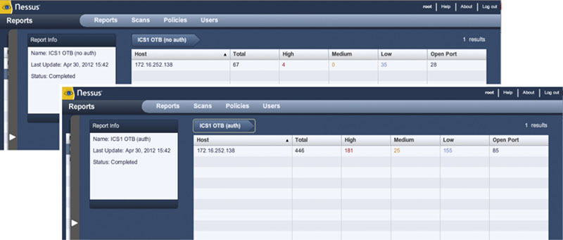
Vulnerability Scanners
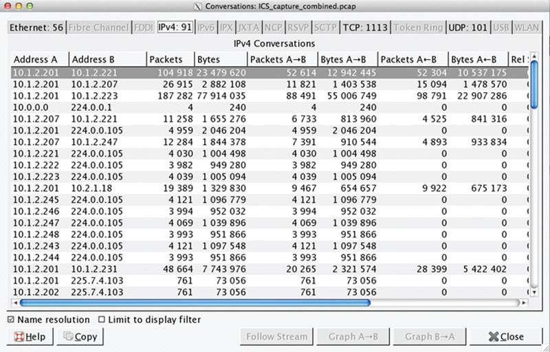
Traffic Scanners
Table 8.7
Wireshark Industrial Protocol Dissectors
Protocol Description
Building Automation Control Networks
Bristol Standard Asynchronous Protocol
Common Industrial Protocol
Component Network over IP
Controller Area Network
ELCOM Communication Protocol
EtherCAT
Ethernet for Control Automation Technology
Ethernet POWERLINK
EtherNet/IP
FOUNDATION Fieldbus
GOOSE
HART over IP
IEC 60870-5-104
IEEE C37.118 Synchrophasor Protocol
Kingfisher RTU
Modbus
OMRON FINS
OPC Unified Architecture
PROFINET
SERCOS
TwinCAT
ZigBee
Live Host Identification
“Quiet” / “Friendly” Scanning Techniques
Potentially “Noisy”/“Dangerous” Scanning Techniques
Port Mirroring and Span Ports
Table 8.8
Minimizing the Risk of Network Scans to ICS
| Target | Typical IT Action | Suggested ICS Action |
| Hosts, Nodes, Networks | Ping Sweep |
• Visually example router configuration files
• Print local route and arp table
• Perform physical verification
• Conduct passive network listening
• Use of IDS on network
• Specify a subset of targets to programmatically scan
|
| Services | Port Scan |
• Do local port verification (netstat)
• Scan a duplicate, development, or test system on a non-production network
|
| Vulnerabilities within a Service | Vulnerability Scan |
• Perform local banner grabbing with version lookup in CVE
• Scan a duplicate, development, or test system on a non-production network
|

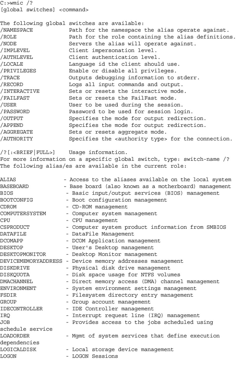
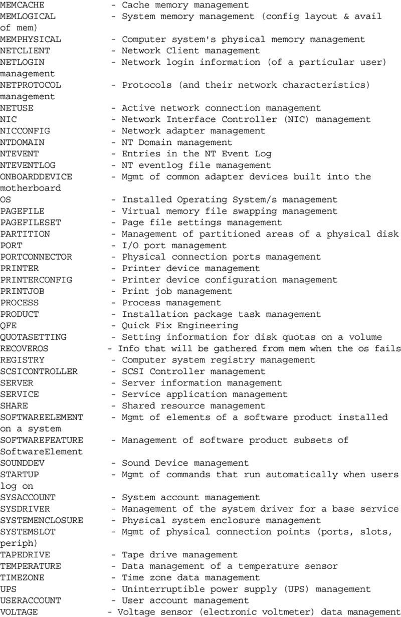
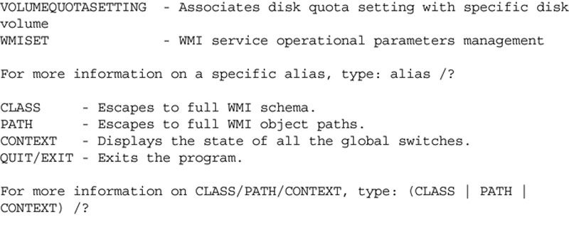
Command Line Tools
Hardware and Software Inventory
Data Flow Analysis
Threat identification
Threat actors/sources
Table 8.9
Common Threat Actors/Sources27
Adversarial
Outside individual
Inside individual
Trusted insider
Privileged insider
Ad hoc group
Established group
Competitor
Supplier
Partner
Customer
Nation state
Accidental
User
Privileged user
Administrator
Structural
Information technology equipment
Environmental controls
Software
Environmental
Natural disaster (e.g. fire, flood, tsunami)
Man-made disaster (e.g. bombing, overrun)
Unusual natural event (e.g. solar EMP)
Infrastructure failure (e.g. telecommunications, electrical power)
Threat Vectors
Table 8.10
Common Threat Vectors
Direct
Local area network – Wired
Local area network – Wireless
Personal area network (NFC, Bluetooth)
USB port
SATA/eSATA port
Keyboard / mouse
Monitor / projector
Serial port
Webcam
Electrical supply
Disconnect switch
Indirect
Application software (via media)
Configuration terminal (via serial port)
Modem (via serial port, internal card)
Human (via keyboard, webcam)
Threat Events
Table 8.11
Common Threat Events28
Adversarial Threat Events
Perform network reconnaissance/scanning
Perform organizational reconnaissance and surveillance
Craft spear phishing attacks
Create counterfeit/spoof website
Craft counterfeit certifications
Inject malicious components into the supply chain
Deliver malware to organizational systems
Insert subverted individuals into organizations
Exploit physical access to organization facilities
Exploit poorly configured or unauthorized systems exposed to the Internet
Exploit split-tunneling
Exploit multitenancy in a cloud environment
Exploit known vulnerabilities
Exploit recently discovered vulnerabilities
Exploit vulnerabilities using zero-day attacks
Violate isolation in multitenant environment
Compromise software of critical systems
Conduct attacks using unauthorized ports, protocols and services
Conduct attacks levering traffic/data movement allowed across perimeter
Conduct Denial-of-Service (DoS) attack
Conduct physical attack on organization facilities
Conduct physical attack on infrastructure supporting organizational facilities
Conduct session hijacking
Conduct network traffic modification (man-in-the-middle) attack
Conduct social engineering campaign to obtain information
Conduct supply chain attacks
Obtain sensitive information via exfiltration
Cause degradation of services
Cause integrity loss by polluting or corrupting critical data
Obtain unauthorized access
Coordinate a multistate (hopping) attack
Coordinate cyber-attacks using external (outside), internal (insider) and supply chain vectors
Nonadversarial Threat Events
Spill sensitive information
Mishandling of critical information by authorized users
Incorrect privilege settings
Communications contention
Fire (Arson)
Resource contention
Introduction of vulnerabilities into software products
Disk error
Identification of threats during Security Assessments
Vulnerability identification
Table 8.12
Common ICS Vulnerabilities
| Category | Potential Vulnerabilities |
| Networks |
Poor Physical Security
Configuration Errors
Poor Configuration Management
Inadequate Port Security
Use of Vulnerable ICS Protocols
Unnecessary Firewall Rules
Lack of Intrusion Detection Capabilities
|
| Configuration |
Poor Account Management
Poor Password Policies
Lack of Patch Management
Ineffective Anti-Virus / Application Whitelisting
|
| Platforms |
Lack of System Hardening
Insecure Embedded Applications
Untested Third-Party Applications
Lack of Patch Management
Zero-Days
|
| ICS applications |
Poor Code Quality
Lack of Authentication
Use of Vulnerable ICS Protocols
Uncontrolled File Sharing
Zero-Days
Untested Application Integration
Unnecessary Active Directory Replication
|
| Embedded devices |
Configuration Errors
Poor Configuration Management
Lack of Device Hardening
Use of Vulnerable ICS Protocols
Zero-Days
Insufficient Access Control
|
| Policy |
Inadequate Security Awareness
Social Engineering Susceptibility
Inadequate Physical Security
Insufficient Access Control
|

Vulnerability Scanning
Configuration auditing

Table 8.13
Bandolier Project ICS Details
| Vendor | Platform |
| ABB | 800xA PPA |
| Alstom Grid | e-terraplatform |
| CSI Control Systems International | UCOS |
| Emerson | Ovation |
| Matrikon | Security Gateway Tunneller |
| OSIsoft | PI Enterprise Server |
| Siemens | Spectrum Power TG |
| SISCO | AX-S4 ICCP Server |
| SNC-Lavalin ECS | GENe SCADA |
| Telvent | OASyS DNA |
Vulnerability prioritization
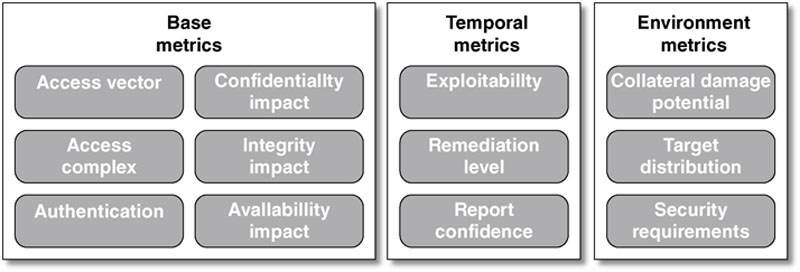
Common Vulnerability Scoring System
Risk Classification and Ranking
Consequences and impact
Table 8.14
Common ICS Consequences
Common ICS Consequences
Impact to quality
Customer reputation
Loss of production
Loss of intellectual property
Economic (micro) impact
Mechanical stress or failure
Environmental release
Catastrophic equipment failure
Localized loss of life
Generalized panic
Economic (macro) impact
Widespread loss of life
How to estimate consequences and likelihood
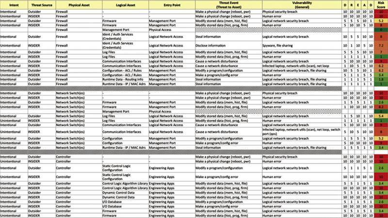
Table 8.15
DREAD Model29
| Rating | High | Medium | Low | Indirectly Measures | |
| D | Damage Potential | Attacker can subvert the security; get full trust authorization; run as administrator; upload content | Leaking sensitive information | Leaking trivial information | Consequences |
| R | Reproducibility | Attack can be reproduced every time; does not require a timing window; no authentication required | Attack can be reproduced, but only with a timing window and a particular situation; authorization required | Attack is very difficult to reproduce, even with knowledge of the security vulnerability; requires administrative rights | Likelihood |
| E | Exploitability | Novice programmer could make the attack in a short time; simple toolset | Skilled programmer could make the attack, then repeat the steps; exploit and/or tools publicly available | Attack requires and extremely skilled person and in-depth knowledge very time to exploit; custom exploit/tools | Likelihood |
| A | Affected Users | All users; default configuration; key assets | Some users; non-default configuration | Very small percentage of users; obscure feature; affects anonymous users | Consequences |
| D | Discoverability | Published information explains the attack; vulnerability is found in the most commonly used feature; very noticeable | Vulnerability is in a seldom-used part of the product; only a few users should come across it; would take some thinking to see malicious use | Bug is obscure; unlikely that users will work out damage potential; requires source code; administrative access | Likelihood |

Risk ranking
Risk reduction and mitigation