Chapter 9
Establishing Zones and Conduits
Abstract
Zones and conduits are a fundamental concept of industrial network cyber security. By grouping similar devices or systems into “zones” according to security levels, and controlling communications between zones, a strong foundation of security will be realized. But how do you know what belongs in what zone?
Keywords
Zone
Conduit
ISA-99
ISA-62443
IEC-62443
Security Levels
Information in this chapter
• Security Zones and Conduits Explained
• Identifying and Classifying Security Zones and Conduits
• Recommended Security Zone Separation
• Establishing Security Zones and Conduits
The concepts of Defense in Depth, as discussed up to this point, have focused on the separation of devices, communication ports, applications, services, and other assets into groups called “Security Zones.” These zones are then interconnected via “Security Conduits” that much like the conduit used to house and contain wire and cable, are used to protect one or more communication paths or channels. The logic is simple—by isolating assets into groups, and controlling all communications flow within and between groups, the attack surface of any given group is greatly minimized.
This concept was originally defined in the Purdue1 Reference Model for Computer Integrated Manufacturing (CIM), which defines the hierarchical organization of CIM systems. The concept was later incorporated into ISA-99 as the “Zone and Conduit Model,” which was later incorporated into the IEC-62443 standard.2
Security Zones, or simply zones from this point onward, can be defined from either a “physical” perspective or a “logical” one. Physical zones are defined according to the grouping of assets based on their physical location. Logical zones are more like virtual ones in that the assets are grouped based on a particular functionality or characteristic.
Security Conduits are actually a special type of zone that groups “communications” into a logical arrangement of information flows within and between various zones. Conduits can also be arranged according to physical (network cabling) and/or logical (communication channels) constraints.
The Zone and Conduit Model has been embraced for a reason. When properly implemented, zones and conduits limit digital communications in such a way that each zone will be inherently more secure. In other words, it is more resilient to negative consequences in the event of a threat exploiting a particular vulnerability within the zone. It therefore provides a very strong and stable foundation upon which to build and maintain a cyber security policy, and by its nature supports other well-known security principles, including the Principle of Least Privilege (where users can only access systems to which they are authorized), and the Principle of Least Route (where a network node is only given the connectivity necessary to perform its function).
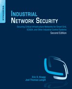
Unfortunately, zones are often defined only in very broad terms, separating the industrial network into as few as two or three zones (for example: a control system zone, a business zone, and a demilitarized zone between the other two). Likewise, conduits are often defined too broadly as “all communications paths within a single zone” or “all communications paths between two zones.” As zones and conduits become more granular, there will be a corresponding improvement in security (Figure 9.1). It is therefore important to carefully identify zones in the early stages of the cyber security lifecycle.

Figure 9.1 Security zones defined by integration levels.
In some cases, such as in nuclear facilities, a five-tier system is mandated, based upon specific regulations (in this case, the Nuclear Regulatory Commission guidelines defined in RG 5.71).3 These guidelines should be treated as a minimum benchmark for zone separation. In most cases, the zones can—and should—be defined much more precisely.
Once defined, zones and conduits will help to pinpoint areas where network and host security and access controls may be required. This is because, by limiting communications to defined conduits, each conduit represents a potential network attack vector. If implemented poorly, zones and conduits will result in a well-organized architecture; if implemented properly, they will result in a highly secure architecture. This is not to say that a zone or a conduit is defined by its security controls, but rather that zones and conduits can facilitate the proper selection, placement, and configuration of security controls. Network security controls—such as firewalls, Network IDS and IPS devices (NIDS and NIPS), router Access Control Lists (ACLs), application monitors, and/or similar security products—will be highly effective when implemented against a well-organized architecture with clear policies that are defined around zones and conduits. As with perimeter defenses, internal defenses should be configured in concert with the authorized parameters of established and documented zones and conduits.
Another way to look at the design and implementation of zones and conduits is how it can be used to provide a more resilient security architecture. Consider a grouping of assets that cannot be protected individually with anti-malware defenses like anti-virus and application whitelisting. These assets can be logically grouped into a zone, and the anti-malware defenses are implemented on the conduit(s) into this zone. This is one effective way asset owners are able to continue operation of legacy and even unsupported systems (e.g. Windows XP) through the creation of zones of related assets, and then applying strong security controls on the conduits entering these zones.
This chapter will cover the identification and classification of zones and conduits. Network and host defenses that can be deployed to directly support the zones and conduits are discussed in Chapter 10 “Implementing Security and Access Controls.” It is also important to define the expected behavior within and between zones, and to monitor all activities within and between each zone—both for the obvious alerts that might be generated by perimeter and host security products and for behavioral anomalies. Baselining activity is covered in Chapter 11, “Exception, Anomaly, and Threat Detection,” while monitoring is covered in Chapter 12, “Security Monitoring of Industrial Control Systems.”
Security zones and conduits explained
The concepts behind zones and conduits can be confusing, and are often misunderstood by those that believe it is simply a new term for the Purdue Reference Model originally released in the late 1980s, and adopted as the ISA Standards and Practice SP95 (also known as IEC-62264). One should realize that the motivation behind the Purdue Model and SP95 was the integration of enterprise and automation applications and the associated exchange of information. These concepts are quite different than those behind the grouping and classification of assets based on particular security criteria.
Each industrial architecture is unique, not because of the selection of equipment, but how each system is deployed in a particular environment (end products manufactured, geographical location, staffing, etc.) and how each system is integrated with other ancillary systems to form a complete, integrated, industrial control architecture. A good analogy to security zones is to consider how many industrial facilities maintain separation of basic control and safety-related assets. This separation occurs, not just because of existing laws and regulations, but because of the underlying layers of protection that each of these systems provides, and how the relative protection of each system is unique. This “safety level” can be applied to each system so that appropriate measures can be in place to ensure that each system performs as intended without unintentional consequences or interactions between systems to impact their basic functionality.
In terms of security, a similar concept can be applied. Assets at a particular site are grouped based on their relative security requirements or “security level.” These zones are then created as either “external” ones, or when multiple layers of protection are required, they can be “nested” inside one another. This allows security controls to be deployed to zones (and the assets they contain) based on the unique security requirements of each. This will be further expanded later when discussing how zones and conduits are classified based on their assets.
Information needs to flow into, out of, and within a given zone. Even in standalone or “air-gapped” systems, software updates and programming devices are typically used to maintain the system. These all represent entry points into the zones, called conduits.4
Identifying and classifying security zones and conduits
One of the greatest challenges in establishing proper security zones and conduits is the creation of a set of base requirements or “goals” that are used to determine if a particular asset should be placed in a given zone. There is no single answer to the method on which this is based—after all, rarely are two ICS installations identical, and therefore, their relative security levels are also never the same.
These requirements or goals typically can be broken down into two broad categories. The first is based on communications and how each asset interacts with other assets outside a particular zone. To explain this in another way, consider a company employee (a process engineer) who uses his/her office computer in the administration building and his/her engineering workstation in the control room. This user is an asset, but which “zone” is he/she a member of? Or is this user in fact a “conduit” between zones? These assets are also typically connected to an industrial network that provides the ability for the electronic exchange of information. This communication can further be designated as “local” or within the same zone and “remote” or outside the zone.
Physical access to assets was explained earlier, and is another means of classifying the assets within a particular security zone. Consider a control room that houses plant operators, technicians, and control system engineers. Though these individuals are all within the physically secure control room, they do not necessarily possess the same level of “trust” with respect to each other. This leads to the creation of embedded zones where a higher security level zone (used by the engineer) is embedded in a lower-level zone (used by the operators) reflecting the relative trust and security of the users.
Assets may exist outside of a particular security zone. This does not mean that these assets are at a necessarily higher or lower-level, but rather a level that is “different” from other assets in the given zone. One of the best examples of this type of zoning exists when you have a particular grouping of assets that utilize a vulnerable or insecure network-based protocol (e.g. Telnet). These protocols are necessary to perform specific functions within a zone that is not meant to contain “hostile” or “untrusted” assets. A manufacturing facility may have multiple areas or work cells that deploy similar equipment and associates zones. In order to properly secure this zone, the conduit(s) into this zone restricts communications prohibiting the use of these less-secure protocols.
Recommended security zone separation
As mentioned, zones may be defined broadly (“control” versus “business” zones) or narrowly, creating zones for highly granular functional groups of assets. The Zone and Conduit Model can be applied at almost any level—the exact implementation will depend upon the network architecture, operational requirements, identified risks and associated risk tolerance, along with many other factors. The following are some recommendations on how to define discrete zones.
Note: When defining highly granular zones, it should be assumed that there will be an overlap that prevents adequate zone and conduit enforcement. For example, a zone created by physical control subsystems is likely to overlap with zones defined logically by specific protocols, and it may be architecturally difficult to separate the two. This is usually okay, and is why most standards and guidance documents reference a broader definition of zones. The process of examining the various ways in which assets can be logically grouped, and how communication can be controlled, is still important and highly beneficial. This will help to identify previously unrecognized areas of risk, and where more granular zones can be defined and controlled. It will also help to improve the overall security posture of the end-to-end network.
When assessing the network and identifying potential zones, include all assets (physical devices), systems (logical devices like software and applications), users, protocols, and other items. Attempt to separate two items, such as a protocol from an asset. If the two can be separated without impacting either item’s primary function, they belong to two functional groups, and are therefore excellent candidates for their own zones. For example, if some SCADA systems use the DNP3 protocol, create a list of all devices currently communicating over DNP3. Assess each to see if DNP3 is necessary to its function or not (it may support multiple protocols, and may be actively using a different protocol to perform its functions). If not, remove it from the functional group, and if possible disable the unused protocol on the SCADA server as well. The result will be a list of all assets legitimately using that protocol (see “Protocols”).
Similarly, consider which assets are connected to each other on the network, both physically and logically. Each represents a functional group based on network connectivity (see “Network Connectivity”) and data flow. Again, assess each item in question individually, and if it does not need to belong, remove it from the group.
A functional group can be based on almost anything. Common functional groups to consider when defining zones in industrial networks include Safety, Basic Process Control, Supervisory Controls, Peer-to-Peer Control Processes, Control Data Storage, Trading Communications, Remote Access, ability to patch, redundancy, malware protection, and authentication capability. Other groups, such as User groups and Industrial Protocol groups, can be considered.
Network connectivity
Functional groups based on network segmentation are easy to understand because networks by nature connect devices together. How the different devices are connected on the network clearly qualify those items that belong to an interconnected group and those that are excluded by an enforceable network connection or conduit. Networks should be considered both physically (what devices are connected to other devices via network cables or wireless connections) and logically (what devices share the same routable network space, subnet or access control list).
Physical network boundaries are easy to determine using a network map. Ideally (although not realistically), all control system networks should have a hard physical boundary in the form of an unidirectional flow that prevents traffic from entering a more secure zone from a less secure one. Realistically, there will be interconnection points consisting of a single link, preferably through a firewall and/or other defensive devices.
Logical network boundaries are defined by the use of devices operating on OSI Layer 3 (routers, advanced switches, firewalls) to separate a physical network into multiple address spaces. These devices provide a logical demarcation between each network. This forces all communications from one logical network to another to go through the Layer 3 device, where ACLs, rule sets, and other protective measures can be implemented.
Note that virtual LANs (VLANs) are a type of logical boundary, but one that is enforced at Layer 2 rather than Layer 3. VLANs use a standardized tag in the Ethernet packet header to determine how they are handled by a Layer 3 device. Traffic destined for the same VLAN is switched, while traffic destined for a different VLAN is routed. VLANs, however, are not recommended for security, as it is possible to modify the packet header to hop VLANs, bypassing the router.5
Control loops
A control loop consists of the devices responsible for a particular automated process (see Chapter 4, “Introduction to Industrial Control Systems and Operations”). Applying this list of devices to a functional group is relatively simple. In most instances, a control loop will consist of a sensor (such as a switch or transducer), a controller (like a PLC), and an actuator (such as a relay or control valve), as illustrated in Figure 9.2.

Figure 9.2 Zones defined by process.
Where defining a functional group based on network connectivity is a broad example that might result in a handful of functional groups, building a functional group based on a control loop is a very precise example. The functional groups created will be numerous, and each will contain a relatively small number of devices (a specific PLC or remote terminal unit (RTU) and a collection of relays and intelligent electronic devices (IEDs)). One of the most practical examples of how this is used in industrial architectures today is in the use of digital field networks (e.g. FOUNDATION Fieldbus) and how particular control loops are placed on dedicated network segments based on classification of risk and functionality.
Supervisory controls
Each control loop is also connected to some sort of supervisory control—typically a communications server and one or more workstations—that are responsible for the configuration (engineering workstation EWS), and monitoring and management (operator workstation HMI) of the automated process. Because the HMI is responsible for the PLC, these two devices belong to a common functional group. However, because the HMI is not directly responsible for those IEDs connected to the PLC, the IEDs and PLC are not necessarily in a common functional group as the HMI (they belong to a common functional group based on some other common criteria, such as protocol use). Figure 9.3 shows an example of two such zones within the broader “Basic Control” zone.

Figure 9.3 Example of supervisory zones.
All PLCs controlled by the HMI are included, as are any “master” HMI, communication servers, or control management systems that might have responsibility or control over the initial HMI (see Chapter 4, “Introduction to Industrial Control Systems and Operations”). Other HMIs are not included, as they are not the responsibility of the initial HMI. Rather, each HMI would represent its own functional group. If a common master controller is in use to manage multiple HMIs, each HMI’s distinct functional group will contain the same master, creating an overlap between multiple functional groups.
Plant level control processes
Every process consists of much more than a PLC, I/O, and an HMI. Manufacturing systems, industry-specific applications, historians, asset management, network services, engineering and operations workstations, and so on all play a part. In addition, a Master Controller, Master Terminal Unit (MTU), or SCADA Server may be used to manage multiple HMIs, each responsible for a specific part of a larger control process (see Chapter 4, “Introduction to Industrial Control Systems and Operations”). This same master device now represents the root of yet another functional group—this time containing all relevant HMIs. Figure 9.4 shows how basic control zones might extend to include other relevant systems that span “integration levels.”
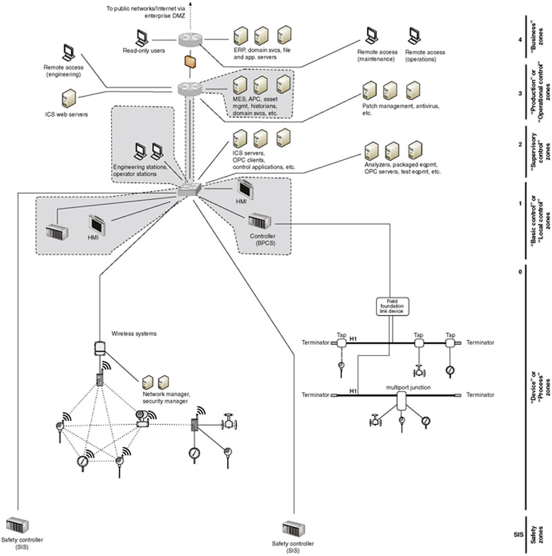
Figure 9.4 Example of plant level zones.
This example also introduces the concept of process communication and historization. If a device or system interfaces with an ICCP server, for example, in order to communicate bulk electrical load to another electrical entity, the ICCP server should also be included in the same functional group. Similarly, if the process information from the device or system is fed into a Data Historian, that system should likewise be included.
Control data storage
Many industrial automation and control system devices generate data, reflecting current operational modes, status of the process, alarms, and other vital manufacturing information. This information is typically collected and “historized” by a Data Historian (see Chapter 4, “Introduction to Industrial Control Systems and Operations”). The Data Historian system may collect data from throughout the control system network, supervisory network, and in some cases the business network, as illustrated in Figure 9.5.
Figure 9.5 A Zone containing all devices feeding into and utilizing data from a Historian.
Not shown here are other devices, such as network attached storage (NAS) devices, storage area networks (SAN), and other devices that may be present to support the data storage requirements of a Historian, especially in larger industrial operations.
Trading communications
The need to communicate between control centers (common within the electric transmission and pipeline sectors) is sufficient enough to justify a specialized industrial protocol, developed specifically for that task. The Inter-Control Center Communication Protocol, or ICCP (see Chapter 6, “Industrial Network Protocols”) connections require explicitly defined connections between clients and servers. Any operation utilizing ICCP to communicate with a field facility and/or a peer company will have one or more ICCP servers and one or more ICCP clients (these can be a single physical server or multiple distributed servers).
One thing to remember when assessing this functional group is that the remote client devices are all explicitly defined, even if owned by another company and hosted at its facility. These remote clients should be included within the functional group, as they have a direct relationship to any local ICCP servers that may be in use.
Because ICCP connections are typically used for trading, access to operational information is necessary. This could be a manual or automated informative process, which most likely involves the historized data stores of the Data Historian (or a subsystem thereof), making the Data Historian part of the “Trading Communications” zone in this example.
Remote access
ICCP is but one specialized method of remotely accessing a system. Many control systems and industrial devices—including HMIs, PLCs, RTUs, and even IEDs—allow remote access for technical support and diagnostics. This access could be via dial-up connection, or via a routable network connection. In the context of security zones and conduits, it is important to understand that “remote access” refers to any communication through conduits to “external” zones. Remote access does not necessarily have to be through wide-area networks over large geographical areas, but could be as simple as two security zones communicating control-related information from one side of the plant to another. When looking at the problem from a zone-and-conduit perspective, they are similar in terms of two “trusted” zones connected via what may be a “trusted” or “untrusted” conduit.
Remote access to control system devices, if it is provided, should be controlled via specialized virtual private networks (VPNs) or remote access servers (RAS), and should only allow explicitly defined, point-to-point connections from known entities, over secure and encrypted channels. These remote access “conduits” should be further secured with enhanced access control methods including end-point policy enforcement, application layer firewalls, and point-to-point authorization. These explicitly defined users, the devices that they access, and any VPN or RAS systems that are used constitute a remote access functional group, as illustrated in Figure 9.6.

Figure 9.6 Remote access zones.
By functionally isolating remote connections, additional security can be imposed. This is extremely important in order to avoid an open and inviting vector to an attacker.
Users and roles
Either a user or another system ultimately accesses every system. Until now, functional groups have been built around the latter—explicitly defining which devices should legitimately be communicating with other devices. For human interaction, such as an operator accessing an HMI to control a process, it is just as important to define which users should legitimately be communicating with which devices. This requires a degree of Identity and Access Management (IAM), which defines users, their devices, and their roles. The most well-known example of an IAM solution is Microsoft’s Active Directory services, although many other commercial IAM systems exist. Figure 9.7 illustrates the concept of a functional group containing a user and those devices that the user is allowed to interface.

Figure 9.7 A zone example based on a user.
Mapping roles and responsibilities to devices can be tedious but is very important, as the resulting functional group can be used to monitor for unauthorized access to a system by an otherwise legitimate user. This is one of the primary reasons many ICS architectures are moving toward a role-based access control (RBAC) infrastructure. RBAC provides a mechanism to configure specific access privileges to specific roles, and then assign individual users to these roles. Typically the responsibilities associated with a given role do not change over time; however, the roles assigned to a particular user can change. An employee with control system access to a certain HMI, upon termination of his or her employment, might decide to tamper with other systems. By placing a user in a functional group with only those devices he or she should be using, this type of activity could be easily detected and possibly prevented (remember, defining functional groups is only the first step to define zones, and once actual zones are defined, they still need to be properly implemented and secured. See “Implementing Network Security and Access Control,” and “Implementing Host Security and Access Control” in Chapter 10).
Protocols
The protocols that a device uses in industrial networks can be explicitly defined in order to create functional groups based on protocols. Only devices that are known to use DNP3, for example, should ever use DNP3, and if any other device uses DNP3, it is a notable exception that should be detected quickly and prevented outright if possible. The areas where a specific industrial protocol is commonly used has already been discussed in Chapter 6, “Industrial Network Protocols.” The specific devices using specific industrial protocols should now be identified and recorded, in order to build one more important functional group, as shown in Figure 9.8.

Figure 9.8 Zones based on protocol use.
Criticality
Zone-based security is about isolating common influencing factors into functional groups so that they can be kept separate and secure from other noninfluencing factors. In terms of functional safety in the plant, this concept has been communicated in terms of the “Safety Integrity Level.” This SIL allows the safety capability of the component to be quantified in order to ensure that similar devices can be deployed in a system and provide sufficient assurance of functionality when demanded. A similar concept known as “Security Level (SL)” has been developed by ISA as part of the ISA-62443 security standards to provide a measure for addressing the relative security of a particular security zone or conduit.
When applied as part of the security lifecycle, a “Target Security Level” is determined during initial system design. This initial level is then used to select components that have a particular “Capability Security Level,” so that components and systems can be selected that help ensure all assets within a particular zone meet the same SL. Once the system is commissioned, a final “Achieved Security Level” can be determined through physical assessment to ensure that the system has been properly installed and commissioned, and that the system meets the desired Security Level once it is in operation.6
The ISA-62443 standard provides a basis for achieving a particular Security Level through the deployment of security controls defined as Foundation Requirements (FR) and associated System Requirements (SR).7 Each SR contains a baseline requirement and zero or more Requirement Enhancements (RE) necessary to strengthen the security assurance. These baseline requirement and REs are then mapped to one of four desired SLs.
The Nuclear Regulatory Commission (NRC) dictates within CFR 73.54 that the criticality of assets be determined so that they can be separated into five logical security zones.8 The NRC security zones are a good example of zone-based security, as the NRC regulatory Guide 5.71 provides clear guidance of how stronger security measures should be used as the criticality of the zone increases.
Critical assets, as defined by the North American Electric Reliability Corporation (NERC), are those that can impact the operation of the bulk electric system.9 They might include control centers, transmission substations, generation systems, disaster recovery systems, black start generators, load shedding systems and facilities, special protection systems, and so on.10 They can be identified using a simple methodology (see Chapter 2, “About Industrial Networks”). Determining the criticality of a zone is a similarly straightforward process, and uses a similar methodology.
Critical assets are extrapolated to the critical function group(s) to which they belong, which may or may not contain other critical and/or noncritical assets. A good rule of thumb is that any zone that contains a critical asset is a critical zone. If noncritical assets are also present in the zone, they must either rise to meet the minimum security requirements of the critical zone, or be moved into a separate zone.
However, simply defining functional groups around criticality to identify zones will result in very few zones (a total of five, using the NRC guidelines). In contrast, the more zones that are defined the stronger the security of the industrial network as whole, and so a broader methodology—which identifies many more distinct zones and subzones—is recommended. Therefore, functionally defined zones should be assessed within the context of their criticality, and vice-versa. In this way, the most critical systems will be protected by an additional layer of separation—for example, the protections between critical and noncritical zones, and then additional protection between systems within each zone.
Granular zoning provides the following benefits:
• It will help to minimize the scope of an incident, should one occur, by further separating systems according to the Principle of Least Route. If an asset is compromised, it will only be able to impact a limited number of systems as the ability to communicate to other zones via defined conduits is restricted.
• It will help to secure critical devices from the insider threat, such as a disgruntled employee who already has legitimate physical and logical access to the parent zone since only limited communication channels are permitted between zones.
• It will help to prevent lateral attacks from one critical system to the next—if all critical systems are grouped together solely because they are all “critical,” a successful breach of one critical system puts the entire critical infrastructure at risk.
Establishing security zones and conduits
It was mentioned earlier that conduits are a special type of security zone, so when it comes to understanding how zones and conduits are created, it makes sense to discuss these together. Conduits are essentially a type of zone that only contains communication mechanisms as its assets. When the word “zone” is used in the context of this section, it shall be assumed to include “conduits” unless stated otherwise.
It was explained earlier that physical and logical assets are grouped into zones. In terms of conduits, these assets are communication assets, such as active and passive network infrastructure (cables, switches, routers, firewalls, etc.) as well as the communication channels that are transmitted over these cables (industrial protocols, remote procedure calls, file sharing, etc.). It was also discussed that early in the security lifecycle, these zones are assigned a relative security level that is used to create the foundation for the security requirements and associated characteristics that will be applied to all assets contained within the zone. These characteristics include
• Security policies
• Asset inventory
• Access requirements and controls
• Threats and vulnerabilities
• Consequences in the event of a breach or failure
• Technologies authorized and not authorized
• Change management process
• Connected zones (conduits only).
As each of the characteristics of a zone are defined, the allocation of assets within the zone become obvious, including the possible creation of nested subzones for particular assets that may be align with other assets within the particular zone. It will then become possible to establish a comprehensive asset inventory that lists physical components, such as computers, network appliances, communication links, and spare parts, as well as logical components like operating systems, applications, patches, databases, configuration files, and design documentation just to name a few.
The assets now contained within a zone are then evaluated for threats and vulnerabilities in order to determine the resulting risk to the zone should these assets cease to perform their intended function. This information will become vital in identifying possible security countermeasures that could be used to reduce the risk resulting from a threat exploiting a vulnerability, and then selecting the appropriate controls necessary to both meet the security level for the zone while considering the cost versus risk trade-off. These concepts were discussed in more detail in Chapter 8, “Risk and Vulnerability Assessments.”
Zones are established considering the technologies that are both allowed and disallowed within the zone. Each type of technology possesses inherent vulnerabilities (both known and unknown) and with these vulnerabilities a certain amount of risk. These technologies must be aligned with security zones in order to prevent one technology from compromising the entire zone. One example many industrial users now face is the concept of “bring you own device” or BYOD within the critical control zones. It is clear that these devices bring with them a certain amount of risk, but by creating dedicated security zones for such devices, it becomes possible to enforce a particular security policy through other controls that may be deployed on the communication channels of the conduit from this zone to other more critical zones.
It is probably clear up to this point how one would take a particular computing asset or embedded device and place it in a particular security zone. What may not be so clear is how to create conduits and assign “communication” assets to these special zones. The easiest place to start is to consider that in most industrial architectures, the physical network is the conduit. Before saying to yourself, “that was easy,” it is important to note that the industrial network only acts as the conduit for “external” communication channels between other assets and zones; it does not represent the channels used to communication between applications and processes that exist within a single asset. These “internal” conduits will become important as the concept of system and host hardening is considered later in this book.
The idea that threats and vulnerabilities exist for computing assets is equally important to communication assets. It is well known that many industrial protocols in use today contain vulnerabilities that, if not properly addressed through appropriate security controls, could introduce considerable risk to not only the device(s) using these protocols, but other devices that may exist within the same zone. It is also important to evaluate the vulnerabilities that may exist within the active network infrastructure, including switches, routers, and firewalls since the loss of any of these components can introduce significant risk to not only the network (conduit), but all zones connected via this conduit. This is why a thorough risk and vulnerability assessment must also be performed for security conduits in order to ensure that appropriate countermeasures have been deployed on the conduit to ensure that the conduit meets the desired security level. (See Chapter 8, “Risk and Vulnerability Assessments”)
The documentation of security conduits—and the communication channels contained within them—is a vital piece of information necessary to accurately deploy security controls throughout the architecture. This document will be used to not only configure upper-level appliances like routers and firewalls that manage access between zones, but also next-generation technologies like application monitoring, intrusion prevention systems, and event monitoring and correlation technologies. One of the leading root causes of compromises to secure industrial networks is from misconfiguration of appliances placed on conduits that connect less-trusted “external” zones to more-trusted “internal” zones. These configuration errors commonly result from attempting to configure the communication access control without sufficient documentation of the content of each of the desired communication channels crossing the conduit. This will be discussed further during “System Characterization” in Chapter 8, “Risk and Vulnerability Assessments.”
Summary
Zones and conduits are abstract concepts designed to group similar devices and control communications between groups, in order to improve security and to minimize the impact of a cyber incident by making it more difficult for malware to propagate unrestricted laterally and hinder an attacker from pivoting between systems. Zones can be used to identify broad groups or highly focused subsystems, supporting the specific operation, business, and technology requirements of a given system. As can be seen in Figure 9.9, which shows how different zones built around different requirements can overlap, this can unfortunately lead to confusion if zones and conduits are not defined carefully and consistently. Once the difficult work is done, the benefits are tangible. The overall infrastructure will become more secure by segmenting systems into zones and controlling communication between zones using controllable communication conduits.

Figure 9.9 Overlapping zones based on different criteria.
..................Content has been hidden....................
You can't read the all page of ebook, please click here login for view all page.