In general, for any system design, the first step is to do the hardware and software partitioning, meaning identifying what goes in the hardware and what goes in the software. The hardware design part was addressed in the earlier chapters.
In the chapters so far, we have discussed the drone system design from hardware perspective, which is the primary objective of the book. In this chapter, now, we will cover the software aspect of the system. The chapter title may not be a great fit since the chapter will not only cover the software development, but will start from the planning and cover the development, integration, and maintenance of the same.
The majority of the software development process and consideration will be similar to any standard software development, which is covered in many books and other material. The key focus in this chapter, therefore, will be to address the drone-specific aspects of software design. There are two such factors: low power and the real-time aspect.
Software Development and Deployment
Software development and deployment is a detailed process consisting of many phases. The overall process flow is called software development life cycle.
Software Development Life Cycle
The software development life cycle (SDLC) is the process of planning, implementing, testing, deploying, and maintaining a software system. In this context, there are multiple pieces of software that need to be developed and then integrated to create a platform and then validated for the right functionality and then debugged in case of issues and then maintained and upgraded as necessary.
Development
Integration
Validation
Debug
Maintenance
In our drone design, a lot of software will be procured from different vendors and only a part of the whole software stack will be developed in-house.
As far as development is concerned, there are multiple stages involved in the development itself: preliminary analysis, system analysis, system design, and implementation. In our particular case, a majority of the software components will be provided by the component supplier, so the real activities will start with integration. However, there are still some components that need to be developed in-house.
In the software development business, various activities relating to the development through maintenance follow specific processes and methodologies. These processes and methodologies put together define a model. In the next few sections, we’ll talk about some of the most prominent models and choose the specific model to employ.
Software Development Models
There are various software development models in practice. By model we mean various processes and methodologies that we apply during software development. The models are chosen based on the nature of the software project, meaning certain models are more suited for specific kinds of projects. The following sections cover a few of the more prominent software development models in practice.
Waterfall Model

Waterfall model
As might be evident, the waterfall method is most suited for systems where the requirements are well understood in advance and there is little chance of any change.
V-Shaped Model

V-shaped model
As is evident, the V-shaped model is suitable only for systems where the requirements are well understood in advance and there is only a little chance of a change in the requirements.
Incremental, Iterative, and Agile
Incremental, iterative, and agile are slightly different but related models.
The incremental model develops an initial implementation, exposes the same to a user for feedback, and takes it through several versions until the complete system has been developed.
The iterative development model aims to develop a system through building small portions of all the features, across all components.
So, the key difference between the incremental methodology and the iterative methodology is that each increment in the incremental approach builds a complete feature of the software, while in the iterative approach, it builds small portions of all the features. In other words, in a sense, during iterative development model, only the implementation part is taken in iterations while the feature set of the product remain the same; however, during the incremental development phase, the feature set changes from version to version.

Agile model
As might be evident, the incremental, iterative, and agile methodologies are most suited for systems where the final feature set is not known in advance (depends upon the customer feedback) and/or the feature set/priority of specific features might change, which is usually the case for most software systems today. It is therefore easy to extrapolate that these methodologies are very common and prevalent today.
This discussion gives a quick summary of the most common methodologies in use. They are not the only models. Other models like the RAD (rapid application development) model and the spiral model are not so common. Bringing the discussion back to our drone design, our requirements are fairly well known in advance, and it not feasible to test the drone at the system level with half-baked/partial features. Therefore, for our system, we’ll use the waterfall methodology.
Having discussed the key processes, methodologies, and models in the software development and deployment, let’s talk about what software components we require, what specific design and development considerations need to be applied, what methodologies/models we apply for each of them, and finally how these components integrate. Let’s start with the software stack of a generic system and then move to the specifics.
Software Stack

Software Stack
Figure 6-4 shows the software components logically organized as layers. At the bottom is the firmware component, which can be considered as part of the hardware as well. The layer above is for the OS and drivers, which are considered the privileged software and can access the hardware and resources that the upper layers (libraries/runtime and applications) cannot. This boundary is commonly referred to as the kernel mode and user mode of operation.
Hardware
Since the system software depends a lot on the underlying hardware, let’s recap the hardware design of our reference drone. At the center is a SoC, which acts as the central point and glues everything together. Then there are various discrete hardware components that are connected to the SoC via various controller interfaces, such as a camera, sensors (including GPS), connectivity (WiFi+BT), a charger, and so on.
Now, from the software perspective, first we need the system firmware, which boots the system up. The system firmware is provided by the SoC vendor. In addition to the BIOS, the system firmware also contains the UEFI (pre-OS) drivers for various components on the system.
With the system firmware the system can boot the UEFI shell. It doesn’t have anything to get to so now we need to install an OS on the system.
System Firmware and Device

Hardware design block diagram
In today’s world (systems), devices have firmware as well. The device firmware, along with the device hardware, provides the specified functionality. Typically, device firmware is part of the device itself. It is, however, possible to upgrade device firmware (which is one of the key reasons for having hardware and firmware as separate entities). There are only few instances when we need to update the firmware of a device already put into market. The device vendors provide proprietary tools and mechanisms along with the updated firmware for upgrading the firmware. The OS vendors create the standards for device firmware update capsule.
The high-level mechanism or architecture of the firmware update capsule is that the OS software passes on the device firmware as a payload to the system firmware. The system firmware then accesses the device and updates the firmware. The device vendors are responsible for ensuring they provide a mechanism for system firmware (UEFI-based) to access the device and update the firmware through an established protocol.
Operating System

RTLinux system architecture
As can be seen, in the RTLinux operating system, there is a layer (the RTLinux layer or RTLinux plugin) between the real hardware and the standard Linux kernel.
The standard Linux kernel is not modified at all, and in a RTLinux operating system, the RTLinux plugin/layer takes over the overall scheduling and proxies to the standard kernel as the hardware. The Real-Time Tasks are directly handled by the RTLinux layer, while the standard kernel is treated as a low priority monolithic task.
RTLinux sits between the real hardware and kernel.
It acts as hardware for the Linux kernel.
It treats the kernel as a monolithic big process.
RTLinux can be downloaded from the Web. It is open source, so we can customize the system as needed.
RTLinux Design
In order to understand the design of RTLinux, we need to understand the architecture and working of the standard Linux kernel. The Linux kernel separates the hardware from the user-level software and applications. The kernel is responsible for scheduling and assigning priority to each task in order to optimize the user experience and performance. The scheduling policy is a priority-based time sharing (FIFO, round robin, etc.) system, which implies that the kernel has the ability to suspend any task once it has consumed the time-slice allotted. This scheduling algorithm along with device drivers, uninterruptible system calls, interrupt disabling (at specific points), and virtual memory usage and operations, are the sources of unpredictability in terms of response time and performance of a task. After executing a task for a predetermined time-slice, the standard Linux kernel could preempt the task and schedule another one. Therefore, the continuity of the task gets lost. If the task doesn’t have a real-time requirement, the task might not realize it since all this switching back and forth happens very quickly. However, the fact of the matter is that in trying to ensure fair distribution of CPU time among all tasks, the kernel can prevent uninterrupted usage of the CPU by any one particular task.
Now, the fundamental expectation from a real-time kernel is that the kernel is able to guarantee the timing requirements of the running tasks. The RTLinux kernel accomplishes real-time performances by removing the sources of unpredictability just discussed. As we can see in Figure 6-6, we can consider the RTLinux kernel as sitting between the standard Linux kernel and the hardware. The RTLinux layer proxies as the hardware, and therefore, the Linux kernel sees the RTLinux layer as the actual hardware. The Linux kernel runs as yet another task, which runs along with other RT tasks. Now, the user can both introduce and set priorities to each and every task. The scheduling of Real-Time Tasks is handled by the RTLinux layer and not by the standard Linux kernel. The user can achieve correct timing for the processes by deciding on the scheduling algorithms, priorities, frequency of execution, and so on. The RTLinux layer assigns the lowest priority to the standard Linux kernel.
Another chance to accomplish the real-time performance is by intercepting all hardware interrupts: only for the interrupts relating to the Real-Time Tasks an appropriate interrupt service routine is run. All other interrupts are passed onto the Linux kernel as software interrupts. The standard Linux kernel runs when the RTLinux kernel is idle. The RTLinux executive itself is non-preemptible.
Yet another tweak to improve the real-time performance is Real-Time Tasks are privileged and therefore have direct access to the hardware, and they do not use virtual memory (virtual memory is one of the biggest causes of unpredictability). Real-time tasks are written as special Linux modules that can be dynamically loaded into memory. The initialization code for a Real-Time Task initializes the Real-Time Task structure and informs the RTLinux kernel of its deadline, period, and release-time constraints.
RTLinux coexists along with the Linux kernel since we don’t need to modify the standard Linux kernel. As discussed, by applying some relatively simple modifications and tricks, RTLinux manages to convert the standard Linux kernel into a hard real-time operating system.

Complete Software architecture with RTLinux
SDK and Libraries
In general, there are many third-party SDKs and libraries available to procure, install, and use for our purposes. In this particular case, we need the Imaging SDKs for surveillance purposes. The OpenCV and GStreamer SDKs are good enough for our sample drone. OpenCV is a vision-related SDK that allows us to make sense of captured data. It allows us to identify the object in an image and take actions based on it, if needed. GStreamer is the media framework that allows us to capture and transform data.
Application
The application layer is responsible for accomplishing the intended purpose of the drone. There are two key elements of the system we are designing: the drone should be able to fly in the specified areas and perform surveillance. As part of the surveillance, the drone needs to capture videos and stream the same to the monitoring station.
It is possible to design the application from scratch on our own; however, many vendors provide software for drones. Skyward, DroneDeploy, and DroneFly are some of the drone software providers in the industry. Using already established software makes it easier, faster, and more efficient to productize the drone.
Since we’re on this topic, here are some open source software packages that allow you to create a drone design and its essential components:
Mach Up: http://insideunmannedsystems.com/ma/
Wired: MIT Software for Drone Design
Key Considerations of Drone Software Design
As discussed in the beginning sections of the chapter, the process/methodology of software development is similar to any other software system. Of the many potential models we discussed, we chose to apply the waterfall methodology since it suits our needs: the requirements are well known and it is of little use to provide a half-baked/partially featured drone to users for feedback/testing (as done in incremental/iterative model).
- 1.
Drones are battery-powered systems, meaning they should run for a while with one charge of battery. So we must optimize the power of the system by applying the low-power design rules/guidelines.
- 2.
Drones are real-time systems, meaning that drones run under very stringent timing/response time constraints. Drones are flying devices that capture/sense the data and they need to process the data and respond/react quickly in order to avoid potentially fatal events.
In the following sections, we will talk about both of these aspects in detail and discuss the specific hardware and software design choices we need to make.
Low Power
A drone runs on battery and needs to be power efficient to run for longer without requiring a recharge (of the battery). This is not to say that systems not running on batteries need not be power efficient. It is important to be power efficient all the time; however, it is all the more important for a battery-operated device to be more power efficient than ones always connected to power.
HW Considerations
- 1.
Components in the system should support different operating performance levels with respective power consumption levels. This allows for optimizing power by means of running at the appropriate performance levels. Since the higher performance level requires higher power and the lower performance level accordingly lower power, by setting the components to the appropriate performance level, the system is able to optimize power.
- 2.
Components in the system should support various sleep states with differing wakeup latency: deeper sleep states consume less power, but have longer wakeup latency. Using the components’ behavior, the system/software can set the idle components to the appropriate (based on wakeup latency) lower power sleep states and thereby save power.
- 3.
The platform should support system-level lower power states: the software can put the system to the appropriate system-level power state by exercising/leveraging these states and thereby save power.
- 4.
And, at the platform design level, the design choices should be made in such a way that the components involved in one use case share the power resources(or in other words, in the same power domain); however, more importantly, the components engaged in mutually exclusive usages should *not* be sharing the power resources. This enables the system/software to switch off the power resource for components not in use and thereby save power.
SW Considerations
In order to understand and appreciate the SW considerations better, we ought to understand the fundamentals of power consumption, followed by the philosophy applied to power saving or optimizations.
Power Consumption of a System
Roughly speaking, systems have two modes when powered on: the first is the active mode when the system is actively being used and the second mode is when the system is on but it’s on standby and waiting for input from the user. In the standby mode, to save power, most of the system components can be turned off since they are idle. To effectively manage the power and state transition, the Advanced Configuration and Power Interface (ACPI) standard defines various system states and device states in detail. Generally speaking, the device/IP is nonfunctional in low-power states. In order to use the device/IP again, one needs to bring the device/IP back to a functional state from the low-power, nonfunctional state. The time taken in the process is called wake-up latency. Again, a general rule of thumb is, the lower the power state, the longer it takes to bring the device/IP to a fully functional state (the greater the wake-up latency).
- 1.
Power consumption in active mode
- 2.
Power consumption in standby mode
- 3.
Power wastage during system wake

Power consumption of a system across active, standby, and transit modes
Power Optimization at the System Level
While discussing power optimization at the system level, we will discuss the optimization on three fronts: active power management, idle power management, and connected standby power management.
Active Power Management
Active power management refers to the management of power when the system is being used. The main thing to understand about APM is the fact that even when the system is in use, only a few of the subsystems are active; therefore, the rest of the system components can be turned off. To this end, the system is designed with use cases in mind, such that when a system is in use in a particular way, only the resources required for that use case are active and the rest can be power-gated to save maximum power.
Idle Power Management
Idle power management is the set of policies that are employed to save power when the system is idle. In modern systems, it is also desirable that the system is able to resume a normal full functional state as soon as there is need for it. The need may arise from an incoming call or the user’s desire to wake the system for normal usage. The idle power management requires that the system is in a state where it consumes as little power as possible. However, the components must be able to become functional in very little time. To this end, there is a lot of effort on the part of the system designers, hardware IP designers, and OS designers.
Connected Standby Power Management
- 1.
System components (at least some) have a state where they consume very little power, all the functional parts are shut down, but they have a portion that is always on and connected.
- 2.
The entry and exit to the low power state is limited and predictable.
- 3.
Offload: System components have built-in intelligence such that they can function and do some basic jobs without involving other system components. For example, the network devices in a connected standby platform must be capable of protocol offloads. Specifically, the network device must be capable of offloading the Address Resolution Protocol (ARP), Name Solicitation (NS), and several other WiFi-specific protocols. And for another example, audio playback can be offloaded such that during audio playback only the audio controller is active and everybody else can go to low-power states (after setting things up for the audio controller, of course).
- 4.Wake: System components have a mechanism to wake the system when required. This occurs in three cases:
- 4.1.
One of the offloaded components has discovered some event for which it needs to involve other system components.
- 4.2.
One of the offloaded components needs assistance from another component to carry out further instructions.
- 4.3.
The user has requested the system to come up for action via any of the interfaces (typically buttons).
- 4.1.
- 5.
The OS and software are designed in such a way that at every small interval the system comes up online, does routine housekeeping, updates the relevant tabs, and goes back to sleep. In this context, modern operating systems have introduced a new concept, time coalescing, which simply means that the recurring booking jobs are aligned such that the system is able to carry out all tasks in one wakeup instance and they don’t require a separate wakeup for each of them, which would be counterproductive to say the least.
ACPI States

Global system power states and transitions
Global and System States
ACPI defines four global states and a total of six system states. The global states are marked G0–G3 while the system states are marked as S0–S5. It must be noted that even though S6 is mentioned in some motherboard documents, it is not an ACPI-defined state. S6, wherever mentioned, corresponds to G3.
- 1.G0/S0: In the G0 state, work is being performed by the OS/application software and the hardware. The CPU or any particular hardware device could be in any one of the defined power states (C0-C3 or D0-D3); however, some work will be taking place in the system.
- a.
S0: The system is in a fully working state.
- a.
- 2.G1: In the G1 state, the system is assumed to be doing no work. Prior to entering the G1 state, the OSPM will place devices in a device power state compatible with the system sleeping state to be entered; if a device is enabled to wake the system, then the OSPM will place these devices into the lowest Dx state from which the device supports wake.
- a.
S1: The S1 state is defined as a low wake-latency sleeping state. In this state, the entire system context is preserved with the exception of CPU caches. Before entering S1, the OSPM will flush the system caches.
- b.
S2: The S2 state is defined as a low wake latency sleep state. This state is similar to the S1 sleeping state where any context except for system memory may be lost. Additionally, control starts from the processor’s reset vector after the wake event.
- c.
S3: Commonly referred to as standby, sleep, or suspend to RAM (STR), the S3 state is defined as a low wake-latency sleep state. From the software viewpoint, this state is functionally the same as the S2 state. The operational difference is that some power resources that may have been left on in the S2 state may not be available to the S3 state. As such, some devices may be in a lower power state when the system is in the S3 state than when the system is in the S2 state. Similarly, some device wake events can function in S2 but not S3.
- d.
S4: Also known as hibernation or suspend to disk, the S4 sleeping state is the lowest-power, longest wake-latency sleeping state supported by ACPI. In order to reduce power to a minimum, it is assumed that the hardware platform has powered off all devices. Because this is a sleeping state, the platform context is maintained. Depending on how the transition into the S4 sleeping state occurs, the responsibility for maintaining system context changes between the OSPM and BIOS. To preserve context, in this state all content of the main memory is saved to non-volatile memory such as a hard drive and is powered down. The contents of RAM are restored on resume. All hardware is in the off state and maintains no context.
- a.
- 3.
G2/S5: Also referred as soft off. In G2/S5, all hardware is in the off state and maintains no context. The OSPM places the platform in the S5 soft off state to achieve a logical off. The S5 state is not a sleeping state (it is a G2 state) and no context is saved by the OSPM or hardware but power may still be applied to parts of the platform in this state and as such, it is not safe to disassemble. Also from a hardware perspective, the S4 and S5 states are nearly identical. When initiated, the hardware will sequence the system to a state similar to the off state. The hardware has no responsibility for maintaining any system context (memory or I/O); however, it does allow a transition to the S0 state due to a power button press or a remote start.
- 4.
G3: Also called mechanical off, G3 is the same as S5; additionally, the power supply is isolated. The computer's power has been totally removed via a mechanical switch and no electrical current is running through the circuitry, so it can be worked on without damaging the hardware.
Device States
- 1.
D0: This state is assumed to be the highest level of functionality and power consumption. The device is completely active and responsive, and is expected to remember all relevant contexts.
- 2.
D1: The meaning of the D1 device state is defined by each device class. Many device classes may not define D1. In general, D1 is expected to save less power and preserve more device context than D2. Devices in D1 may cause the device to lose some context.
- 3.
D2: The meaning of the D2 device state is defined by each device class. Many device classes may not define D2. In general, D2 is expected to save more power and preserve less device context than D1 or D0. Devices in D2 may cause the device to lose some context.
- 4.
D3 Hot: The meaning of the D3 Hot state is defined by each device class. Devices in the D3 Hot state are required to be software enumerable. In general, D3 Hot is expected to save more power and optionally preserve device context. If device context is lost when this state is entered, the OS software will reinitialize the device when transitioning to D0.
- 5.
D3 Cold: Power has been fully removed from the device. The device context is lost when this state is entered, so the OS software will reinitialize the device when powering it back on. Since device context and power are lost, devices in this state do not decode their address lines. Devices in this state have the longest restore times.
Processor States

Processor power states
It is clear from the above discussion that detecting inactivity and putting the devices and eventually the system (if possible) in their low power states forms the heart of power management software.
Linux Power Management
In Linux, the power management software manages state transitions in association with device drivers and applications. It circulates the PM events, including standby state transitions and sleep state transitions, to various software components. This way the software components can participate in the state transitions decisions. For example, based on the situation, individual components can veto certain state transitions.
Since most of the devices have operating context or state, there is a need to save and restore the same as and when the devices transition into and out of the low power state. Based on the Linux power management protocol, device drivers are responsible for saving the device’s state before putting it into a low-power state and restoring it before the device becomes active. Applications usually don’t engage in the power management activities directly.
The overall scheme of power management is rather simple. The power management system discussed earlier plays the central role. All drivers that need and want to participate in the system state transition activities register with the power management system. The power management system maintains a list of all registered drivers. At the time of registration, the driver also provides a callback function for state transition events. The power management system is aware of the system state transitions and invokes the callback function of all participating (or in other words, registered) drivers. The callback function does the processing based on the state transition event type and returns an integer value: a return value of zero indicates that the reporting driver agrees to the state transition event, and at the contrary, a non-zero return indicates that the device driver doesn’t agree to the state transition request. The nonzero return value causes the power management system to abort the state transition flow.

System in running state

System in standby state
At the time of driver unload (say when the device is removed or something of that sort), the driver can call upon the PM system to indicate that it is not interested in participating in the PM events and wants to unregister. And, as expected, the PM system will not bother the driver (on state transitions) once it has unregistered itself from the PM system.
From the system power management perspective there are two models/protocols/specifications: APM and ACPI. APM is rather older than ACPI. ACPI is the specification most systems follow; however, APM is also supported on Linux. In order to enable support for APM, however, we need to compile with CONFIG_APM=y. Also, we need to tell bootloader to use APM instead of ACPI. APM and ACPI are mutually exclusive and we need to tell the bootloader appropriately.
The driver is written for devices in such a way that it works for the device across all platforms, generally. That implies that the driver should not assume any specific system/platform design and should not hardcode any values that will change from platform/system design to design. Drivers, however, might need some parameters that depend on the platform design. The information may be needed by the driver to make the device functional, or power management transitions, and so on.
The question is what mechanism should we apply to pass these specific parameters to the driver? The answer to this is ACPI, again. ACPI, as part of the specification, provides a mechanism for drivers and the ACPI BIOS to communication by means of ACPI tables. The ACPI BIOS creates and exposes various tables to the OS. These tables are consumed and used by the drivers at runtime. These ACPI tables can and do contain data/values and also methods. Since these methods (BIOS) are written/developed for a specific platform, they know platform design-specific details. These methods, therefore, could perform a platform-specific job when invoked. These methods are particularly useful for power management activities like switching on/off a particular power rail.
- 1.
_PRx: _PRx (where x could be 0, 1, 2, or 3, respective to each supported device state) methods specify what power resources are needed for the device to operate in state Dx. The ACPI framework in the OS needs to ensure that when the device transitions into Dx, power resources for the same are turned on. _PRx methods are defined in a particular device node scope and apply to that particular device.
- 2.
_PSx: _PSx(where x could be 0,1,2, or 3, respective to each supported device state) methods are called when the device transitions to state Dx. _PSx is intended to perform any platform-specific actions required during these transitions. Similar to _PRx, _PSx methods are defined in a particular device node scope and apply to that particular device.
- 3.
_SxW: On a given platform, there is a specific mapping between device states that supports the wake capability and system states that can respond to wake events. ACPI defines the _SxW (where x could be 0,1,2, or 3, respective to each supported device state) objects to provide this information to the operating system. There is an SxW object for each supported system power state, Sx.
- 4.
_CRS: _CRS is used to describe the resources for a device. Similar to _PRx, _CRS methods are defined in a particular device node scope and apply to that particular device.
- 5.
_DSW: ACPI defines the _DSW object as a way for the operating system to inform the ACPI platform firmware about the next sleep or low-power idle period.
- 6.
_PRW: _PRW is used to specify any additional power resource that may be needed for a device to be enabled for wake. _PRW is also used to define the wake capability for traditional PC platforms.
Similar to _PRx, _PRW methods are defined in a particular device node scope and apply to that particular device.
The ACPI code needs to provide these callbacks that are used by the ACPI framework. The code is based on the platform design. The mechanism enables a separation between the platform-specific operations and the platform-agnostic, device-specific operations. This allows the device drivers to focus on the platform-agnostic operations/flows and rely on the ACPI callbacks to do the platform-specific operations like switching on/off a particular power resource, and so on.
Real-Time Systems
A drone is a real-time system, meaning it has to process and respond to events within the stipulated maximum threshold time in order to avoid a system malfunction. Real-time systems run with resource and time constraints. In order to design a robust real-time system like a drone, we need to make specific design choices in HW and SW. The HW and SW considerations for a real-time system are discussed in the following sections.
Hardware
In a simple system, the control logic is easy to design. There could be one simple loop that checks for the events that need servicing and performs the necessary actions. However, as the system complexity grows (with multiple functions, events, and priorities), the control system complexity grows accordingly.
As control systems become more complicated, it is increasingly difficult to manage the various MCU functions with a simple control routine. With multiple events with different priorities, a single control loop just cannot get to every function quickly enough. And, for a real-time system, all events need be serviced within their required response time.
Timer
In order to satisfy the need, we need a real-time approach to control, which can ensure that events are serviced within their stipulated/required response times. One option for improving real-time response is to use a real-time operating system or RTOS. In this approach, every task in the control system can be assigned a time slice of the CPU processing cycle. If a particular function doesn’t need the time allocated currently, it can “turn over” the time to another function so that precious processing cycles are not lost. Modern CPUs have been optimized to make it easy to implement RTOS implementations. One of the key features is inclusion of a dedicated timer that is used for determining processing allocation, which makes it easy to allocate time slices to functions/tasks.
Advanced Interrupt Controller
Because RTOS-based systems need to respond to real-time events quickly and efficiently, it is important to optimize the interrupt processing time. This is because, if the interrupt takes too many cycles to respond, real-time response will suffer. Also, if the device interrupts are multiplexed due to a lower number of interrupt lines/vector available on interrupt controller, the software will have to spend a lot of time trying to figure out the source of the interrupt (by reading all the devices that are multiplexed into a line). It is therefore necessary for the system to have an advanced interrupt controller to optimize the interrupt processing time.
Context Switching
While switching from one task/function to the other, there are a plenty of things that need to change: registers, memory, and so on. MCUs provide HW support for faster context switch and make it easier to have a predictable response time.
Memory
Ensuring required data and code availability to the MCU for operation is essential to meet the response time requirement. Even correctable faults (for example, page faults) can add unpredictable latency, which a real-time system may not be able to tolerate. In fact, the virtual memory system is one of the key contributors to the response time unpredictability.
Data Processing Throughput
The associated processing units/DSP should be capable of supporting the compute/processing requirement of the system.
Priority
Since in the real-time system top priority tasks should always run first (and should be able to preempt the current running process if a higher priority task comes in), there needs to be a mechanism to assign priorities to tasks, preempt the tasks based on priority, and context switch to the new task.
The SoC chosen for our reference drone design does support the above HW features and therefore is suitable for a real-time system design like a drone.
SW Considerations
In addition to the specific hardware considerations, there needs to be a few considerations during software design. It must be noted that the software considerations are for the same purpose or need: designing a real-time system that can respond and complete the work in a stipulated time, reliably.
Interrupt Handling
While discussing the HW consideration topic, optimized interrupt handling is essential to accomplish the real-time performance requirement. Because multiple interrupts are often present in the system, prioritization needs to happen. In other words, the most important task must always be serviced within predefined time constraints regardless of other events.
Also, the maximum contribution to the interrupt latency is due to non-reentrant or critical processing paths that must be completed before the interrupt can actually be processed.
Real-Time Operating Systems
There are so many operating systems available to choose from and most of the time there is no clear choice. We need to make tradeoffs in terms of capabilities and other features. At a high level, today there are two classes of operating systems used for real-time work: dedicated RTOSes designed exclusively for real-time applications and general-purpose operating systems that have been enhanced to provide real-time capability. The use of a real-time executive makes real-time performance feasible for a general-purpose operating system.
Real-Time Languages
In order to improve the real-time performance of the software system, the usage of specially designed real-time languages is helpful. Ada, HAL/S, and CHILL are a few real-time languages. Even though it is possible to use a general purpose language like C or Java, because of the special requirements of performance and reliability demanded by real-time systems, the choice of programming language is important. Many general purpose programming languages (e.g., C, FORTRAN, Modula-2), however, can be used effectively for real-time applications.
Task Synchronization and Communication
In a multi-tasking system there is a need for different tasks to pass information. There is also a need to have a synchronization mechanism across tasks. In a real-time system, semaphores are commonly used to implement and manage the mailboxes used for synchronization.
System Software Integration and Bring-Up
In the preceding sections, we talked about how to develop and/or procure the software components that are required for our drone software system design. Once these components are available, we need to integrate them to make the system. In the following sections, we will talk about the steps we have to follow to make a system out of these components.
System Bring-Up
The first step in making the system is to bring up the base system. Bringing up the core system means assembling the hardware, applying the firmware to boot the system, installing the operating system, and enabling the system interfaces. We need to follow a step-by-step procedure to bring up the system.
System Firmware
As you might imagine, the first step is to assemble the hardware as prescribed earlier. Once the hardware is assembled, the next step is to get the system firmware. The system firmware needs to be flashed in the SPI NOR (for our design choice). The system firmware is provided by the SoC vendor, and it may have multiple subcomponents depending on the SoC design/vendor. The SoC vendor provides the tools and mechanism for flashing the system firmware.
The system firmware is responsible for the system initialization. Please note that there are two components to the system firmware: the first is related to the SoC, and the other is related to the rest of the platform. The SoC-related part is responsible for initializing the SoC components and interfaces, and the platform-related component is responsible for initializing and setting up the rest of the components on the base board.
The platform-related component of the system firmware comes from the SoC vendor as a reference (based on the reference platform, the SoC vendor would have created it for internal consumption and validation). We need to make the changes based on platform design and components.
Once the system firmware is flashed and the system is powered up, the system will be able to boot to an built-in mini operating system (EFI shell). Since there is no other operating system installed yet, the BIOS boot up process will launch the EFI shell and stop there. The next step is to install RTLinux (the operating system we chose earlier).
OS (RTLinux)
As you know, RTLinux is basically a patch over the standard Linux kernel. RTLinux talks directly to the hardware and acts as a proxy for hardware to the Linux kernel. In order to install RTLinux, the first step is to compile the RTLinux patch for the specific Linux kernel version.
It should be noted that RTLinux versions and Linux kernel versions are two separate things. For our instance, we are going to use RTLinux 3.1. The kernel patch for Linux kernel 2.4.4 is named kernel_patch-2.4. Please note that the RTLinux kernel patch is available for other kernel versions as well: for example, kernel_patch-2.2.19 is for kernel 2.2.19.
The kernel and respective RTLinux patch need to be downloaded and patched. The Linux patching process is the same as applying any other patch to the kernel. After the patch process, the kernel and modules need to be built and installed. After the installation, we reboot the system and then configure and enable the RTLinux. Once Linux/RTLinux is installed, the system firmware boot up process will launch this new OS.
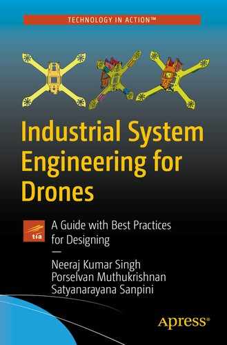
Drivers/Modules
In the RTLinux (Linux) world, the hardware drivers are developed as modules and compiled and installed. In the current context, drivers for a majority of the devices are already part of the mainstream kernel code. Please note that despite the fact that drivers may be part of the same source base, they may not be part of the kernel inherently. At the same time, once the modules are loaded, they become part of the kernel itself. The modules are loaded using the insmod command and removed from the kernel using the rmmod command. While developing modules, no libraries are linked to the modules/kernel and therefore we should not include any of the standard header files or use any of the functions from the standard libraries.
Linux Module Loading Process
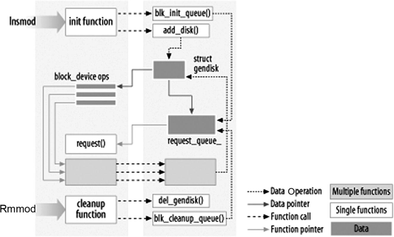
Sample SoC block diagram
- 1.
There are controllers that are part of the SoC we chose. The internal block diagram of a sample SoC, for example, might look like Figure 6-14.
As you can see, there are many controllers like I2C, SPI, USB, UART, PCIe, Audio, Graphics, and Camera/Imaging controllers on the SoC. In this case, the drivers for these controllers (within the SoC) are provided by the SoC vendor, unless they’re already part of the OS by default.
- 2.
The second category is those that are located on the board as discrete components and are connected to the controllers on the SoC. The cameras, sensors, and WiFi+BT modules fall into this category. These components are provided by separate vendors and the drivers are provided by the respective vendors, unless they’re already part of the OS. When making the component/design choices, we need to investigate whether a driver (for the specific OS of choice) for the component is provided by the respective vendor. If the driver is not provided by the vendor, we need to develop a driver on our own by referring to the device/components specification. Given the fact that there are so many vendors and plenty of choices while choosing the components, there is almost no reason to choose a component that does not have a driver for the OS of our choice. There may be a remote case where we absolutely need to choose a component for which the driver is not available, and we must develop the driver on our own. However, it’s best to avoid such a case since the time, effort, and resources required to develop a driver for a non-trivial component is significant.
Now that we have the drivers for the components on the system, we must load the drivers for them to start operating. The drivers are written as Linux loadable modules, and are loaded with the insmod command; to remove or unload a driver, rmmod is used. Once these drivers are loaded and start operating, we are ready for the application layer. The application layer uses these drivers to interact with the hardware.
Libraries/Middle Layer and Application
As discussed, the application layer is responsible for bringing the system to life by means of supporting the intended usage. And libraries make the application development easier by means of providing commonly used functions, APIs, and framework. As far as the bring-up activity is concerned, libraries and applications are more or less the same. Both are user mode components. As discussed, the libraries we need (OpenCV and GStreamer) can be downloaded from the Web and installed, and we need to procure the application software (home grown or delivered by any one of the drone software providers), install it, and start using the same. There is also a need for remote control and monitoring software. This remote control and monitoring software runs remotely and connects to the drone system over the network/internet protocol. The application software can be developed and installed like any other standard application software.
Verification, Validation, and Maintenance
Once we have all the software components put together, we need to ensure that the components individually and as a whole system meet the requirements. There are various aspects of requirements, such as functional, performance, stability, reliability, and security. Verification and validation ensure that the systems meet all of these different requirements.
Verification and validation are related but slightly different practices. Verification is the process of evaluating software to determine whether the product at a given development phase satisfies the conditions imposed at the start of that phase. Verification is static practice of verifying documents, design, and code. Review, inspection, and “walk through” are some of the mechanisms to carry out verification. Another key point to note is that verification can determine whether the software is of high quality or not; however, it doesn’t ensure that the system is functionally good.
Validation, on the other hand, is the process of evaluating the product at the end of development to determine whether it satisfies specified requirements. It is a dynamic process and is accomplished by various kinds of testing and end user trials. There are various types of testing, categorized based on different parameters: mechanism, methodology, and level. In the following sections, we will do quick survey of the various types and methodologies, and make a decision on what kind of testing and methodologies apply to our system.
Based on the Mechanism
Manual testing: It is carried out manually. Manual testing requires a lot of people and resources, and therefore limits the coverage.
Automated testing: Automated testing uses software and tools to test a system. Some of the software and tools are developed to carry out a specific type of testing; therefore, we may need to use many different tools to cover all of the aspects of testing.
Based on the Methodology
Black box testing : In black box testing, tests are defined, designed, and performed without knowing and/or worrying about the internal implementation. It only relies on the inputs provided and expected output.
White box testing : In white box testing, the internal implementation is known to the tester and the test cases and inputs are chosen by the tester, keeping in mind the internal implementation.
Gray box testing : As the name indicates, gray box testing is a combination of black and white box testing. In this case, the tester has some knowledge of the implementation (at least the high-level interactions), but doesn’t know all the low-level implementation detail, and the test case definition follows accordingly.
Based on the Testing Level
- Functional testing : As part of the functional testing, the system is tested against the functional requirement. There are different levels of functional testing:
Unit testing : During unit testing, individual units of source code like functions and classes are tested in isolation.
Integration testing : During the integration testing, multiple modules are put together and tested as a group.
Smoke and sanity testing : As part of the smoke testing, right after the build/integration, some sets of tests are performed to ascertain that critical functionalities of the software system are working fine. Sanity tests are performed, focusing on the specific fixes/changes in mind. The intent is to ascertain whether the fix looks reasonable to go ahead with further testing.
System testing : In system testing, the testing happens at the system level (with respect to expected system functionality) to ensure that the system meets the specified system requirements.
Regression testing : The regression testing ensures that the changes to the software don’t break the existing functionalities (in a way that adversely affects the system).
User acceptance testing (UAT) : UAT is performed to ensure that the system meets the stated end use requirements. There are two stages in UAT: the alpha testing is done on the developer side, while the beta testing is done on the end user/consumer side. UAT is also known as end user testing (EUT) or acceptance testing (AT).
End-to-end testing : End-to-end testing is performed to exercise the complete flow of the application/software system. It is usually done after system testing, and is carried out in a real-world scenario and environment.
- Non-functional testing : There are many nonfunctional tests carried out to ensure various aspects of the system. Some of the key non-functional test categories are summarized below:
Performance testing: Performance testing is carried out to ensure that the performance needs of the software/system are met in terms of speed, scalability, stability, and reliability.
Load testing: Load testing is performed to check the system behavior under both normal and anticipated peak load conditions.
Stress testing: Stress testing is performed to check the system behavior at load beyond the anticipated peak load conditions (and what the system can handle). This is done by driving an unusually high load on the system.
Security testing: Security testing is performed to ensure that the system is safe from attacks like SQL injection, DoS, identity spoofing, cross-site scripting (XSS), and more. There are tools to statically analyze the software and identify potential security issues.
Now coming back to our drone system software, we apply both manual and automated testing. We apply different coverage to different components/areas: for the components availed from third parties (external world), we apply black box testing, while for internally developed components we apply gray box testing mixed with white box testing. As far as the functional test is concerned, all of the stages are performed for the software components developed internally, while for the components procured from external sources (third parties) we start with integration testing and go all the way to end-to-end testing. Security testing is part and parcel, and one of the most important aspects of overall validation.
Maintenance is about ensuring that the critical needs of software are met in terms of bug fixes and critical feature upgrades to keep the system running. In our case, we do not plan to upgrade the drone software with new features; however, we will need to fix any critical bugs if and when identified.
Conclusion
In this chapter, we discussed the drone software design and development. We discussed the software development life cycle, the software stack, and drone software design considerations, followed by the system bring-up, validation, and maintenance. The specifics of the components and features will depend on the purpose and design of the drone. However, the overall flow and process will remain similar for any drone software design.