Stage 1
Preparation and Brief

Chapter overview
Stage 1: Preparation and Brief is a decisive stage within the overall project process, during which the Strategic Brief is tested against early ideas and responses using Feasibility Studies, Site Information and research, and the suggested scope, approach, responsibilities and services required to deliver the appropriate information are outlined within the Initial Project Brief.
The key coverage in this chapter is as follows:
While the Initial Project Brief represents the primary information exchanged at the end of Stage 1, there are a number of key tasks and activities completed throughout the stage that will fundamentally inform the design process. Ideally, these should also be finalised prior to progressing to Stage 2. These two key work streams can be loosely defined as information gathering and information planning. Information gathering typically covers:
Information planning will develop:
Understanding what information will inform and assist the development of the Concept Design is central to the development of the Initial Project Brief, as is the way the data will be formatted and exchanged. The standards and protocols used to produce the project data will facilitate the accurate transfer of information between team members. It is therefore important that these are clearly understood as they may affect the development and communication of ideas later within the project. The outcomes and aspirations identified within the Strategic Brief will have suggested the likely key project team members required to develop the design. This stage allows for the full Schedules of Services to be finalised, based on the emerging brief and feasibility studies. The Design Responsibility Matrix outlined in the RIBA Plan of Work 2013 Toolbox (www.ribaplanofwork.com) and the Digital Plan of Work BIM Toolkit (https://toolkit.thenbs.com) can be utilised to highlight the specific Project Information requirements and who will be responsible for delivering them during each stage. If particular information or disciplines are not appointed or delivered, either in full or in part, until a later stage, the lead designer should ensure that all the implications and risks are reviewed and understood before finalising the project scope. The Core Objectives of the RIBA Plan of Work 2013 at Stage 1 are:
The Core Objectives support the development of the Initial Project Brief and are progressed from a review of the Strategic Brief, the development of the Project Objectives, including the Project Outcomes, and Feasibility Studies to ensure the brief and site are aligned. They are set out as outlined in the following sections. The Initial Project Brief will provide a coherent record of the Site Information and Feasibility Studies and the key project decisions in a format that can be reviewed by all those who will commence design work at Stage 2. It will also clearly identify the Project Outcomes and Project Objectives and the direction the design should follow within subsequent stages. The Initial Project Brief should consider:
The Strategic Brief outlines the overall vision within the Project Objectives and Project Outcomes in relation to the Business Case. The Initial Project Brief refines this ‘high level’ information, identifying what the key project decisions are, when they need to be taken, who will be required to develop the design and what the project team’s overall scope might be.
The Initial Project Brief – information checklist Typically, the information developed within the Initial Project Brief will include:
The information documented should be appropriate to the project scale and size. Too much information can obscure the overall intent, so it is important to consider what might be omitted from the brief for clarity. Some projects may require detailed reports under the headings outlined above, in which case an executive summary can be used for setting out the more significant issues, ensuring the most important information is instantly accessible. Appendices and supporting documents can also be used for larger reports. The final format of the Initial Project Brief and any other project documentation should be considered from the outset. Structuring the key project documents in a consistent way will avoid reproducing and reworking information for use elsewhere and will allow it to be presented and represented in a coordinated and coherent format.
Formatting information Careful consideration should be made when deciding on the appropriate software to collate this information. Different design disciplines often use different document publishing and spreadsheet software, which can make the overall compilation very time consuming and unproductive. The lead designer will be responsible for collating the coordinated information at Stage 3 and their preference for the format and presentation software and the design team’s ability to produce information accordingly should be determined at this stage to assist in the transfer and communication of key information here and in the later stages. Feasibility Studies help to define the requirements of the Initial Project Brief, which must outline the project approach in relation to specific sites, the composition and requirements of the project team and, ultimately, what the project team will produce and when. The vision, Project Outcomes and key functional requirements outlined within the Strategic Brief will provide the basis for testing the detail of the Initial Project Brief, reviewing:
These early studies may highlight that the preferred location is not the most suitable or that the client’s aspirations can be achieved using a more efficient solution than that envisaged. Moreover, the site location and orientation might significantly influence any preferred design location in favour of delivering a more efficient and sustainable approach. The key criteria and decisions developed from these studies should be documented, outlining the viability of each option as well as any areas of information and work required to progress and test each solution. The potential costs can also be reviewed and compared against the Project Budget to determine the relative value of each approach.
Feasibility Studies – information checklist The Feasibility Studies might include:
This stage represents the starting point for the creation of the Project Information. The project team should ensure that all the data can be reviewed, validated and reused efficiently by other team members when exchanged, especially given that the procurement strategy chosen will affect the Contractual Tree for the preparation of the Concept Design. At the outset of this stage the project team may have already accumulated a significant amount of Site Information from the client and other sources. The full extent and format of the information available needs to be collated, reviewed and validated in order to identify whether it is of any use, if there are any omissions and where further research and information may be required. Understanding the specific site and project requirements will help to identify any statutory, geotechnical, existing building and topographical constraints as well as what further Site Information might be required to inform the design. There are a number of areas that should be explored to identify the project Site Information requirements and provide a comprehensive overview of the existing conditions. These include:
Reviewing these areas provides an opportunity for the project team members to familiarise themselves with the site and its context and will help to identify any requirements for additional detailed surveys. It is important to identify what survey information is needed as early as possible, how it should be produced and who would be best placed to provide it. Some clients will be able to procure surveys from consultants they will have engaged previously; alternatively, the project team will need to define the scope and survey requirements clearly for the client to procure tenders and proposals from suitable surveyors. Following the development of the scope it may be beneficial to walk the site with the preferred surveying consultants to understand the key requirements and areas where additional information may be required. Any resulting omissions and additions should be added to the final scope, which should also identify the level of detail required and the format of the survey information, the appropriate standards and protocols. The information should be geo-located, in accordance with the emerging Technology Strategy.
Scoping surveys The scope for site surveys can cover a number of areas, including:
3D surveys can typically be viewed and used within standard CAD software, but they can also be provided in a ‘flattened’ format for use in a 2D environment. Subject to the project requirements, programme and cost constraints, it may be beneficial to procure a 3D survey and distil the information into a 2D file, if that is the required format for the project. The 3D view will be maintained and can be used to help the project team understand the layout of the site, even if the final information is utilised in a linear format.
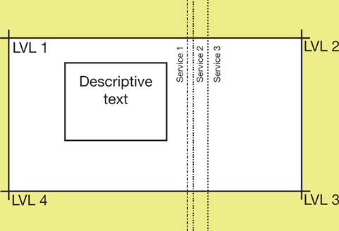
Formatting surveys Figure 1.1a
Layered survey information, plan view Figure 1.1a shows how layered survey information might appear when viewed on screen and figure 1.1b shows it in a more conventional plan view. By separating the annotated information from the geographical data, the structure of the file allows the features of the site to be reviewed in an uncluttered format, while the actual data can be used and viewed in plan as a visual check. Also, if the modelled information is geographically located in relation to the agreed project datum, each point within the file will correspond to its associated annotated value, allowing levels to be understood without necessarily needing the 2D notes and values. Figure 1.1b
Layered survey information, model view Regardless of which final format is required for the information, ensuring that the data is structured appropriately and in accordance with the project standards is essential to the progression of future design information. When scoping a 3D survey, it is beneficial to specify that text and numerical data are separated vertically from the actual model representation. Ensuring that the survey information is set out in accordance with the project requirements will avoid unnecessary reworking by the project team and will significantly reduce the risk of information becoming corrupted or inadvertently amended or deleted when being adjusted for clarity of view. It is also possible to specify the use of point cloud technology to provide surveys of existing site conditions and buildings. This process is relatively easy to complete and its cost is becoming more comparable with that of other 2D and 3D survey methods. Point cloud data can be converted into a BIM-compatible file format for use within a Project Information Model (PIM) and can also be supplemented using colour 3D photography to help identify specific services or elements within the recorded data.
Point cloud information Laser technology can be used to automatically take a large number of measurements from the surface of an object. The process creates a digital cloud of geometrical points, the point cloud, which can be viewed as a 3D representation of what has been scanned. A 3D CAD/BIM model of the existing buildings or site conditions can then be created from the point cloud data for use in editing software. It is important to always specify whether the conversion process is required. For more information on using point clouds refer to BIM in Small Practices by Robert Klaschka (RIBA Publishing, 2014), Case Study 07: Using existing building BIM, and www.thenbs.com/topics/bim/articles/pointCloudSurveys.asp As with Stage 0, the Information Exchange for Stage 1 focuses on a single output:
This stage also has an equivalent exchange within the UK government’s Digital Plan of Work (dPOW):
Data Drop 1 represents the first required exchange of developed information in the dPOW process and comprises a modelled response to the plain language questions (PLQs) addressed throughout this and the previous stage. The information should be sufficient to deliver an initial Construction Operations Building Information Exchange (COBie) output to validate its development, to ensure that the design and Initial Project Brief are aligned and to allow the outline Business Case to be approved. The COBie output identifies and collates the non-geometric information that is needed to exchange managed asset information over the life of a project (figure 1.2). PAS 1192-3:2014 defines an asset as an ‘item, thing or entity that has potential or actual value to an organization’, noting also that:
The information is extracted from the BIM model in a simple spreadsheet format that can accommodate large and small project models, allowing the team to document specific information both spatially, by floors, sectors and zones, and physically, by actual product types, components and systems. While the process is set out to manage the constructed elements of the project during the In Use stage, the dPOW requires COBie data to be documented as it is created within each stage of the design, construction and commissioning process. This approach simplifies the work required to record and document the data at the completion of the project.
Standards and protocols BS 1192-4:2014 Collaborative production of information. Fulfilling employer’s information exchange requirements using COBie. Code of practice This specification focuses on the client’s information expectations and requirements for each stage of the project and how COBie can assist in its production. A crucial point is that the dPOW assumes that projects will follow a procurement route that allows the earliest involvement of the contractor and its supply chain. To give them the best possible information at the start of Stage 2, Data Drop 1 includes a BIM model derived from the Feasibility Studies containing spatial allocations, environmental parameters and any other constraints. During Stage 1, the PLQs in support of the modelled Data Drop can be used to demonstrate an understanding of:
While the development of the brief will use the defined Project Outcomes and Project Objectives to inform the design concepts, the Suggested Key Support Tasks and Project Strategies will support the way in which the information is structured, managed and progressed. The Stage 1: Preparation and Brief Key Support Tasks include the preparation or agreement of:
The need for project protocols and processes will depend on the size and complexity of the project and the number of disciplines involved. However, even on a small project a Project Execution Plan will be a valuable document. The plan should develop:
The size of the project may affect the detail within the Project Execution Plan, which should ideally be completed as the design progresses so that it will capture and communicate the necessary information. The Project Execution Plan should be developed early on within the Preparation and Brief stage to record any key project decisions, and also to outline specific areas that may affect the project scope, fee
Project Execution Plan – information checklist A typical Project Execution Plan will contain the following:
and management requirements. Managing the development of the design will ultimately ensure that, irrespective of the composition of the project team and however it might change over the course of the project, the support systems and procedures are clear, concise and easily operated.
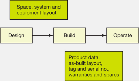
Project Execution Plan requirements For smaller projects, simply producing one or two lines documenting how the design will be developed, when information is to be produced and where it will be located, will benefit the progression of the works. So too will producing a record during the Construction and In Use stages of how the project was delivered and how it performed against the original outcomes and requirements. In addition to preparing the Information Exchanges required for construction, it is also important to form an understanding of how design information will be used during occupation and operation. Such requirements are typically outlined within the Handover Strategy and Employer’s Information Requirements (EIRs), which, in addition to highlighting issues relating to project completion, phased handovers, commissioning and other post-occupancy activities, will set out what information the client requires for the In Use stage, perhaps as part of a Soft Landings or similar process. Understanding how these strategies will be developed will enable the project team to make allowances within the initial scope, fee and appointment for post-occupancy services, the restructuring of any ‘As-constructed’ Information and the appropriate management of modelled information ‘In use’. Issues that are likely to affect the progress of the project should be identified as early as possible within the process, recorded and maintained within stage Risk Assessments. Assessments made at this early stage should be considered as an opportunity to acknowledge project constraints, to recognise objectives and priorities and to identify and mitigate the impact of any critical areas within the emerging ideas. These initial reviews will be based on known site constraints and information developed within the Feasibility Studies, but it is essential to continually review any likely risks on receipt of additional and developed Site Information to understand if any have been mitigated. The management of remaining risks can be allocated to an appropriate project team member to develop a suitable response. Should the project develop without this specific advice – for example, the client may wish to keep the design team to a minimum, to avoid a sizeable fee during these initial stages – specialist advice may be delayed. These risks should also be identified within the Risk Assessment as they may result in considerable reworking of the design and additional costs within subsequent stages. The way we produce and utilise information on projects is constantly changing, influencing the way we communicate within the project team. The standards, processes and protocols used to facilitate these collaborations need to be determined as early as possible to ensure the accuracy and efficacy of the information produced and its proper management throughout the construction and occupation of the design. The Project Execution Plan outlines a number of different strategies to control these processes so that, even on small projects, the team can ensure that the right information is validated and communicated at the right time. The Communication Strategy will outline the ‘who, what and how’ procedures that relate to information being discussed, issued, reviewed and checked, while the Technology Strategy will define the way information is created and managed within the project team. The Communication Strategy should typically outline protocols for:
Many of the above will be outlined within each discipline’s quality assurance (QA) system. The Communication Strategy for the project may therefore:
If a definitive QA system is not outlined then the RIBA Quality Management Toolkit can provide a good starting point for controlling the key project processes. The RIBA Quality Management Toolkit The RIBA Quality Management Toolkit comprises:
Outlines the philosophy behind the Toolkit approach and operation. Highlights the processes for running individual projects – incorporating a simple, single-sheet short form for small projects, consultancies and investigations. Over two sections, the guidance outlines the use and operation of systems that comply with the requirements of the international standard BS EN ISO 9001:2000:
The Quality Manual is a declaration highlighting commitment to the quality management system. Provides essential procedures covering both office and project processes. It includes templates and more detailed work instructions.
The Technology Strategy sets out the hardware, software and format protocols to be used by the project team in developing and coordinating the design. Information production within the construction industry is currently going through a transitional period, developing from the more traditional 2D/3D CAD drawings and documents into a predominantly data-driven modelling environment. The Technology Strategy, especially during this transitional phase, is a critical document for defining the structure and format of the information, how it will be managed and how it will be developed, ensuring that any misunderstandings that could arise as a result of the production method or configuration are avoided. Understanding the software and processes utilised by each discipline, including the differences and their implications, will ensure that software does not become a barrier to collaborative working. Issues relating to the hardware and software used should be considered prior to any design work commencing. However, as the design progresses and information from specialist designers, subconsultants and contractors is integrated, a review of these strategies, ideally at the beginning of each stage, will be required. The procurement strategy adopted may also mean that the project team will change at specific stages. If this is the case, the structure of the information should be developed to ensure seamless exchanges throughout the course of the project. The increased uptake and use of CAD has led to design consultants producing numerous single-party documents and standards that locally define and control the production of information. Given the differences within these standards and the lack of a common approach, coordinating the different disciplines has become increasingly problematic. BS 1192:2007 Collaborative production of architectural, engineering and construction information outlines a number of standard methods and procedures to structure and manage project information. These protocols allow information to be created accurately and collaboratively, minimising any errors and delays associated with poor input and management. This standard has also recently been developed and expanded to support BIM processes outlined within:
It is important at this early stage to ensure that the Technology Strategy outlines that any information produced on the project, whether CAD or BIM, maintains the collaborative requirements and standards set out in these documents, including as a minimum:
The Technology Strategy will document the standards and procedures that the project information will be developed from, and any specific CAD or BIM protocols will be outlined or appended. The 2D/3D CAD standard or the BIM execution plan (BEP) should ideally be used to form the basis of the Technology Strategy. The adoption of a coordinated and consistent approach will maximise production efficiency, while the standards and best practices set out will ensure the delivery of high-quality and uniform information.
BIM execution plan A BIM execution plan (BEP) will include:
The Technology Strategy should be considered by all members of the project team and viewed as a live document; it should continually be updated via a series of reviews and workshops. The document should be revisited at the beginning of each stage. A number of CAD standards and BEPs have already been developed within the industry. The Construction Industry Council (CIC) has produced a suite of documents in support of the government’s BIM objectives, including a BIM protocol template that can help to define the contractual and legal requirements of a project BIM model when appended to the main contract. It can also be used by the project as a starting point for setting out the BIM requirements by adding project-specific details to the appendices:
CIC BIM Protocol The CIC’s BIM Protocol can be downloaded from http://cic.org.uk/publications Whether a project is developed using 2D/3D CAD or through a BIM approach, it is important to understand what level of definition (LOD) will be achieved by the Project Information at the end of each stage and what that data can be used for. LOD is an acronym developed primarily in support of BIM data, although it can also be used within a CAD environment. While seeking the same objective, there are a number of recognised interpretations for LOD. In the US, where the term was developed by the American Institute of Architects, it stands for ‘level of development’, and uses numerical definitions (LOD100, 200, 300 etc.) to describe the graphical content of components within a design. These are explained further within the BIM Forum’s recently published Level of Development Specification. In the UK, further to the release of PAS 1192-2, and the development of the dPOW, LOD is more commonly used to describe the ‘level of definition’. LOD has also been used to represent the ‘level of detail’ or ‘level of design’ contained within the Project Information; however, within the context of this guide, it should only be understood to mean the ‘level of definition’, unless otherwise stated. LOD is defined in PAS 1192-2 as the collective term for two specific areas of information:
LoD sets out the graphical content and LoI sets out the information, or data, required to describe and maintain it at each stage of the project. Sitting behind the dPOW are some 5,000 object templates providing guidance for defining the appropriate LoD and LoI for a number of architectural, structural and MEP (mechanical, electrical and public health) construction objects. These in turn will shape the information requirements and exchanges for each stage of the project. These objects (which become deliverables when associated with a project using the dPOW) reinforce the areas defined within the Design Responsibility Matrix, helping to align the ‘what’ with the ‘when’ and ‘who’ with respect to the Information Exchange requirements in response to the EIRs. Within a dPOW, the LoD and LoI are numerically defined to reflect the work stages (these are broadly comparable to the RIBA stages, see figure 0.2), setting out guidance for what should be delivered within each Information Exchange. A construction element can, for example, have a level of definition (LOD) of 2-2, meaning that the detail and information provided are comparable with what would normally be required at the end of the Concept Design stage (Stage 2). LoD or LoI within the LOD can also be increased at a given stage to reflect specific project design or procurement requirements. For example, a curtain wall might be developed by a specialist subcontractor at Stage 3 and the design team might therefore be required to provide an LOD of 3-3 at the end of the Concept Design, providing the specialist subcontractor with the appropriate LOD to progress the design during Stage 3. An LOD of 2-2, as defined within the dPOW, is highlighted in figures 1.3 and 1.4.
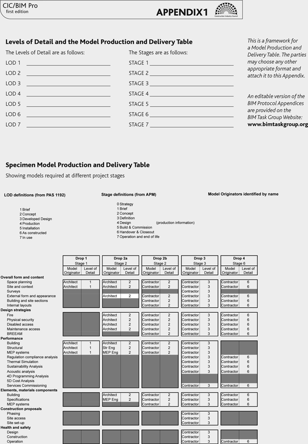
Digital Plan of Work The Digital Plan of Work BIM Toolkit is available at https://toolkit.thenbs.com. The way that LOD is defined, measured and assessed is fundamental to outlining the purpose of the information produced. It underpins the content of each Information Exchange throughout the Concept Design, Developed Design and Technical Design stages as well as setting out what is required at handover for the operation and maintenance of the project during the In Use stage. Perhaps more importantly, LOD defines the reliability of the Project Information: the extent to which it has been and can be considered by the design team at that particular stage. The CIC BIM Protocol’s Appendix 1, Model Production and Delivery Table (MPDT) (figure 1.5), uses an LOD system and provides guidance on how to apply the approach to each stage. While the definition notes that PAS 1192-2 sets out the basis for this LOD, the guidance does highlight that a separate standard is envisaged to set out specific requirements. It is likely that the LoD and LoI descriptions provided within the dPOW will provide the basis for this, defining the specific data content and requirements for the project. This protocol allows the BIM requirements to be appended to the project appointments so that clear responsibilities for information production are set out contractually. Following the launch of the BIM Toolkit and the dPOW, this document and a number of other standards will be updated to reflect the LOD guidance and its specific referencing system based on project stage and content. Other standards and protocols have been developed to help manage and define the Project Information, such as the generic and, in some cases, software-specific guidance and templates developed by AEC (UK).
BIM standards and protocols The AEC (UK) BIM Protocol and standards can be reviewed at http://aecuk.wordpress.com AEC (UK) has also produced a number of software-specific PIM validation checklists, which outline how a model should be exchanged for collaboration and which are extremely useful for managing the size and appropriateness of each model file. These documents outline a best practice approach to producing and managing information. They provide a good starting point for those developing a CAD or BIM methodology, as well being a helpful reference for those who are already working with BIM standards. The Construction Project Information Committee (CPIc) has also produced a suite of documents in accordance with PAS 1192-2 and aligned with the procedures outlined by the government’s BIM Task Group. The CPIx protocols include pre- and post-contract BEPs, with the pre-contract plan used to address the issues raised within the government’s EIRs, and the more detailed post-contract plan used to help outline the methodology that suppliers/contractors will use to deliver the project BIM. Beta versions of the CPIx BIM strategy templates are available to download for use at www.cpic.org.uk/cpix Understanding how LOD defines the extent and content of information produced during a project enables the project team to highlight who will be responsible for producing the information and what level of definition it will comprise at each specific stage. This can be defined within an MPDT, as outlined above, or through a Design Responsibility Matrix, which can subsequently assist in defining the project team’s Schedules of Services.
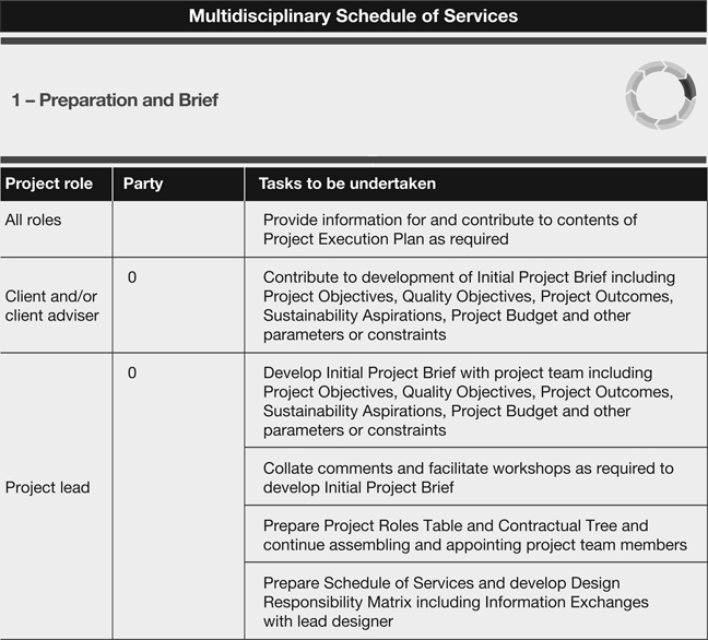
The Design Responsibility Matrix The Design Responsibility Matrix is one of three tools developed in support of the RIBA Plan of Work 2013 and can be accessed via the RIBA Plan of Work Toolbox at: www.ribaplanofwork.com The Toolbox is presented in a simple spreadsheet format, containing customisable templates for:
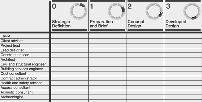
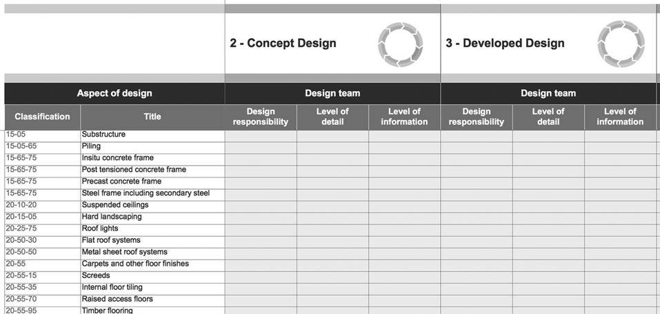
The website and the associated RIBA publication Assembling a Collaborative Project Team provide detailed guidance on how to utilise the Toolbox to allocate consultants’ design responsibilities, the design interface with any specialist subcontractors and the overall scope of services. The LOD and LOI columns allow design responsibility to be defined in an ‘analogue’ manner (using scale and specification) or by using LOD references defined by the dPOW or elsewhere. The dPOW sets the information required for the Design Responsibility Matrix, and once completed should export directly into scheduling software. However, the Design Responsibility Matrix can also be completed collaboratively by team members, using the RIBA Plan of Work 2013 Toolbox schedules. The Project Roles Table (figure 1.6) allows for project team members to be defined at Stage 1 of the RIBA Plan of Work. While some specifics may not be known at this stage, the general thrust and requirements of a project team can be set out. The Design Responsibility Matrix (figure 1.7) enables the project lead to define what information is to be provided to progress the design at each stage, when it is to be provided and by whom. The spreadsheet highlights typical building elements and systems that a project might utilise, based on the Uniclass 2 classification system. Each item can then be attributed to the disciplines outlined within the Project Roles Table using a series of simple pick lists (see Stage 2: page 79). The Multidisciplinary Schedules of Services (figure 1.8) outline who, following completion of the Project Roles Table and Design Responsibility Matrix, will complete specific tasks within each stage of the project. This multidisciplinary approach sets out a framework for the coordination and integration of the design information. Aligning these ensures that the design will be progressed at the same LOD during each stage, avoiding some of the risks and errors that can occur if information is produced ‘out of sync’. It also helps identify the risks of not engaging the services of some design team members during specific stages and what reworking/additional work might be required if this approach is followed. Understanding the Project Information requirements at this stage is critical to setting out what data is exchanged and who needs to produce it. A review of these requirements at the end of this stage and Stage 2 will reaffirm the overall approach. It may also start to highlight specific procurement approaches, which may then impact what information is to be provided, when and by whom.
Chapter 1 summary
The Preparation and Brief stage defines the Initial Project Brief. This document will be developed and supported through a number of Feasibility Studies based on the collated and reviewed Site Information, the requirements for assembling the project team, the project scope and the associated design responsibilities. Through the development the Technology and Communication Strategies, defined within the Project Execution Plan, the project can define protocols and standards collaboratively to manage the information production and workflow, either in 2D/3D CAD or within a BIM environment. This will allow the structure and accuracy of data collected and produced to be standardised and verified in a usable format so that the key information can be utilised within the Feasibility Studies, the Initial Project Brief and throughout the future design stages, minimising any reworking and inefficiencies created through incompatible processes, scopes and approaches. It is important to ensure that, as it develops, the information production and management is controlled through the Project Strategies and that the disciplines responsible for its completion in this and any future stages are aware of what should be produced, for what purpose and to what level of detail. Outlining these requirements early within the project will allow each discipline to programme resources appropriately. This will ensure that all areas of the design are suitably tested and explored, improving both the efficiency and quality of the overall process and project. The Stage 1 Information Exchange is:
Additional Information reviewed might include:
Introduction
What are the Core Objectives of this stage?

Producing the Initial Project Brief
How does the Initial Project Brief differ from the Strategic Brief?
![]()
General
Procedural
Functional
Environmental
Statutory
Financial
![]()
Developing Feasibility Studies
![]()
What Site Information is required?
![]()
Existing buildings
Environmental
Topographical
Contextual
![]()

![]()
What are the Information Exchanges at the end of Stage 1?
What is COBie?
![]()
Strategies supporting the Initial Project Brief
What information is required within the Project Execution Plan?
![]()
Project description (summarised from the strategic and initial brief documents)
Project organisation (summarised from the strategic and initial brief documents)
Project controls
Project development (reference only, typically added at Stage 2)
Change control (typically added at Stage 3)
In Use processes (developed with information from the Handover and Maintenance and Operational Strategies)
![]()
Developing a Handover Strategy: what allowances should be made for the project ‘In Use’?
How the Project Execution Plan can be used to manage project risks
Structuring Project Information
How should information be managed?
![]()
How are different information production systems integrated?
Why use design protocols and CAD standards?
Where should digital protocols and standards be outlined?
![]()
![]()
How should LOD be defined?
![]()
![]()
AEC (UK)
CPIc
Understanding roles and responsibilities
![]()
How can the Toolbox be used to outline information requirements?