Stage 3
Developed Design

Chapter overview
During this stage, the preferred design solution will be developed to ensure that all the key building systems and interfaces have been coordinated and are aligned with the Cost Information. Subject to the procurement strategy, the responsibility for information production may shift from the design team employer to the contractor, either at the outset or at the end of this stage. In these instances, the Project Information needs to be developed to precisely describe the key areas of the design, with any remaining elements clearly identified to be completed by the contractor. Ensuring that the Project Information is structured in accordance with the defined project standards and protocols will be paramount at this stage in order to facilitate the use and exchange of data between the design team as well as any new designers that are appointed to assist in finalising coordinated design.
The key coverage in this chapter is as follows:
The Developed Design stage will provide the minimum level of information needed to complete a coordinated design and, if required, the submission of a full planning application. Clarity of the level of detail and information to be produced by the design team will be essential to progressing to the next stage, and the information requirements, Schedules of Services and appointments should all be suitably aligned to ensure the information is resolved collaboratively. On many projects, the structural and MEP (mechanical, electrical and public health) systems and other design inputs included in the planning submission might not have been resolved to the same level as the architectural design. While minimising the design input in this way prior to seeking a planning approval does ensure that the client is not overexposed in relation to design fees, without the collaborative input of all members of the design team, aspects of the design may not be properly coordinated, which creates risks for the client in the Stage 4 design, and might require adjustments during Stage 4 to the Developed Design consented by the planning authority. Those proceeding on such a basis should be aware of the risks. A better approach is to develop an integrated solution collaboratively from the outset. The Developed Design stage has been structured to support a collaborative approach, aligned across the design team, ensuring that the design and any planning application produced at this stage are fully coordinated, avoiding the need for out-of-sequence redesign exercises. Some clients will still prefer to minimise their financial risk; in these cases the Design Responsibility Matrix (DRM) can be used to highlight the minimum information requirements for the stage to minimise any associated design, programme and cost implications if a collaborative route is not progressed. Reviewing the DRM will also identify areas where design input from specialist subcontractors might be required, and, although the procurement route might not be completely resolved, their advice and technical support can be integrated within the Developed Design to ensure that the interfaces between various systems are considered and accommodated. The Core Objectives of the RIBA Plan of Work 2013 at Stage 3 are:
During this stage the design team will utilise the Final Project Brief and Concept Design to progress a coordinated Developed Design. All the key Project Strategies and approaches will be developed by all the appropriate design team members to align the design with the level of definition requirements highlighted within the Design Responsibility Matrix, the Project Execution Plan and the Technology Strategy. The importance of structuring and producing information in a way that facilitates collaborative working has been outlined in the previous stages. The need for a collaborative working process as set out within BS 1192:2007 and PAS 1192-2:2013 and a common data environment (CDE) has also been identified. A CDE provides a more efficient and collaborative way of working, ensuring that many of the procedural and file management tasks are integrated within the overall process, especially when the process is operated collaboratively online.
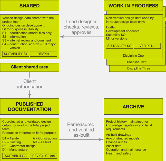
Using a common data environment Smaller or less complicated projects might not be able to meet the expense of a web-based management system. However, if a CDE is viewed primarily as a process and the basic principles are followed, the same efficiencies can be achieved on these projects. Exchanging work-in-progress information and communicating changes in an email or transmittal allows the design to progress and avoids abortive work; for example, a designer who is working in isolation will be prevented from taking an incorrect solution too far. Developing and exchanging information collaboratively, in line with the four main CDE processes outlined within BS 1192, will benefit coordination and help prevent duplication, waste, errors and inconsistencies when information is shared and validated. A CDE can be utilised with a CAD or a BIM approach, to manage how data is created and exchanged by the project team members at each particular stage of development. A CDE comprises four distinct areas (figure 3.1):
Adopting these management standards is important, but doing so should not require significant changes to the processes and composition of any existing information management systems, only to the way the information is structured, validated and, most importantly, exchanged. ‘Work in Progress’, for example, defines the status of the information. WIP information does not necessarily need to be separated from other Project Information, it just needs to be outlined within a protocol to ensure that all those working within the project environment understand where WIP information will be stored and how it will be managed and exchanged. Existing company or project standards, if defined, should be able to accommodate the process, and adopting these standards and methods of working should not be seen as a barrier to collaboration. Operating a CDE will not define the format for exchanging information. This should be resolved at a project level within the Project Execution Plan and Technology Strategy. All project team members should contribute to this process so that the most appropriate approach to sharing all types of information can be determined. Sharing information underpins a collaborative workflow, allowing the design to be developed with the most up-to-date information and, whether utilising a CAD or a BIM approach, it is important to ensure the information exchanged is appropriate and ready to be used by other disciplines. In order for information to move from one area to another within a CDE, it must pass through a sign-off procedure, which validates the content and appropriateness of the data. These gateways should be developed to suit the project specifics; however, the BS 1192 CDE process suggests that:
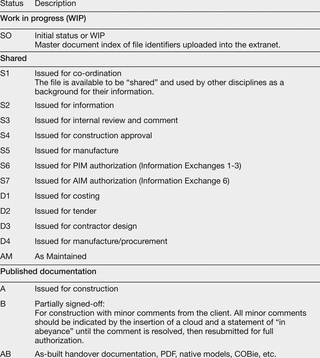
The standard outlines that in order for design information to be shared it must achieve a status that is ‘fit for coordination’. Data can then be uploaded to a web-based system or circulated to all members of the team via email or an alternative data exchange method in accordance with the Communication Strategy outlined within the Project Execution Plan. To ensure that the purpose of the information exchanged is understood and that it is used as intended, the CDE introduces the idea of ‘status codes’ to be included within the file naming protocols (figure 3.2). These codes allow the project team members to utilise the information on the understanding that its use and impact on their own information will be restricted by its status. As coordinating the design is an iterative process it is important to ensure that when files are updated and exchanged, especially WIP
files, all the developments are documented. This can be within the files themselves, on the issue sheets or within accompanying emails or web-based communications or through a project schedule. This will ensure the design can be progressed collaboratively, and that abortive work associated with the developing design is avoided. When the design achieves a particular level of definition (LOD) then the relevant model files can be composed to create drawings, including plans, sections, elevations and 3D model excerpts. With a BIM model, the drawing will represent a particular fixed view or cut through of the model itself. These model views are set out within a drawing sheet template, which will record the details of the project and the name of the drawing, its number, revision and status.
Models While models developed using BIM are compositions of 3D objects and despite CAD being predominantly a 2D approach, BS 1192 specifically refers to any drawn piece of information as a ‘model’ file. Models contain the current design and can be edited natively or when exchanged through an interoperable format. BS 1192 defines model files as a ‘collection of containers organized to represent the physical parts of objects, for example a building or a mechanical device’. It also notes that ‘Models can be two-dimensional (2D) or three-dimensional (3D), and can include graphical as well as non-graphical content. This standard is based on generating, sharing, etc., model files, not just drawings. Drawings are produced when the model is complete, correct and consistent’, and that ‘Models can include information by reference’.
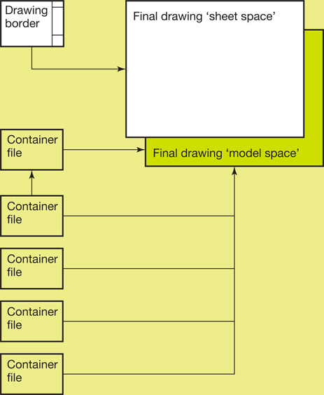
Composition of CAD files Figure 3.3 is based on the AEC (UK) CAD Standard for Drawing Management v.2.4 (2005) Best Practice Model of CAD File Composition and shows how model files should be used to configure design information. Model files will contain the relevant project information, such as the grid, building layout, structural or servicing layouts, and can either be collated within a separate container file, prior to being referenced into the model space of the final drawing, or be placed directly into the drawing and arranged, cropped and reformatted to suit the drawing output. The drawing border is referenced directly into the final drawing sheet space. The drawing file will typically be exchanged in a non-editable format, such as a PDF file or paper hard copy.
Figure 3.3
CAD drawing file composition
When information is no longer relevant to the project it should be archived or superseded to prevent it being used unintentionally. If the CDE process is managed through a web-based system it will tend to do this automatically, with all re-versioned files archived during the progression of the project; however, these may also be stored locally by individual disciplines. The lead designer should retain a copy of all versioned information from all disciplines. This collection of files may become quite large, but making regular backups, following the completion of a stage for example, will help to manage the size of the archive. This process will provide a detailed history of the Project Information, as well as retaining key decision points throughout project. Archiving can also be used to maintain a copy of all the relevant information outlined within the Handover Strategy, such as:
PAS 1192-2 develops the BS 1192 CDE processes to suit a BIM approach. It describes the shared use of individually authored models as a single source of information for any given project, used to collect, manage and disseminate all the relevant approved project documents throughout the project team. Figure 3.4 highlights how the BS CAD standards have been adapted. The basic principles of the CDE are retained, with the four main areas of information. However, the design stage CDE includes a Client Shared area, which sets out the Employer’s Requirements and may include access to information on an existing building or a building to be refurbished. It is important that the project team members understand the impacts that any design input from specialist subcontractors might have, as these areas may only be developed generically until the actual detailed information is provided. The Design Responsibility Matrix (DRM) makes provision for this input to be considered during Stage 4: Technical Design, and it can
also be noted under a separate column at the end of the worksheet (as downloaded from the RIBA Plan of Work Toolbox: www.ribaplanofwork.com) (figure 3.5). Specific areas that might require design input from specialit subcontractors should be outlined in the DRM when known. This should be possible at the outset (Stage 1) based on sector norms. This approach may affect the scope and programme of the design, but it will avoid any early abortive work or reworking of detailed information during the later stages. Specialist subcontractor design information can be integrated directly into the model during the design, fabrication and installation process. When a single federated model is used to accommodate this, PAS 1192-2 recommends that a ‘change of ownership’ procedure is operated at the relevant stage to ensure the responsibility for any objects, components and assemblies that replace the design intent is always defined. While these changes in model ownership need to be fully understood by the project team members, the design and coordination of each key interface between packages remains the most important exercise at this stage to avoid impacting the constructed quality. The project team will need to ensure that any interfaces are resolved collaboratively to reflect the intended design, performance and construction requirements. The status codes within the PAS (figure 3.6) have been amended to include the issue of the Project Information Model (PIM), the Asset Information Model (AIM) (see Stage 6: Handover and Close Out, page 193), manufacturing models and the documentation sign-off processes. Every project will have its own requirements and the CDE process set out within BS 1192 and PAS 1192-2 should be used as a best practice guide to outline the principles of managing and coordinating Developed Design information. The use of web-based systems may offer slightly different approaches, subject to the way the information is accessed and stored, the actual system being used and the amount of information being exchanged, but the process remains essentially the same.
Figure 3.7
PIM drawing file composition
A BIM workflow should be structured in a similar way to the composition of CAD information. However, drawings can be extracted from each individual discipline’s model or from the federated model (figure 3.7). Views from the model – plans, sections, elevations, detail callouts and 3D views – can be ‘extracted’ to the drawing sheet model space or to a separate drawing file, where they can be embellished with additional 2D detail and setting-out and graphical information, such as:
Using a simple view from the BIM model to produce the drawing is a small but very significant difference from developing information in CAD. Using information developed from views allows the drawing to retain a dynamic link with the model, ensuring that the primary information in the drawing will be updated automatically when changes are made within the model. Model updates can then be reviewed quickly in conjunction with the drawing and any embellished detail adjusted accordingly. For example, revising the setting out of an internal wall will ensure that all of its associated interfaces at, say, the floor and ceiling will update automatically within the model and any embellished information within the drawing depicting the materiality, section location, specification or additional construction detail, such as fixings, adhesives or tolerance allowances, can then be quickly amended according to the revised location. Most information models will be drawn to reflect a level of detail that would normally be represented at a scale of 1:50. Adding more detail can create large and unmanageable model files, which are difficult for the project team members to exchange and use. Drawings can also be produced without retaining a direct link. However, separating the drawings from the developing model can lead to coordination issues. Changes made to embellished files or the main drawings can affect the overall setting out of the components and assemblies. Therefore, if the updated information is not manually transferred back into the model, significant discrepancies may develop as the design progresses. The principles of managing the design and of federating models are set out in figure 3.8. Each separate discipline’s model is progressed locally; when it is ready for exchange it can be shared with the project team and
federated by the lead designer or BIM coordinator. This federated model may also exist within the Shared area of the CDE to allow all members of the project team to review their designs in context. Whenever the model is updated, the amending discipline should notify all other members of the team that revised information is available. The model coordination process does assume that there is a centralised area for sharing models, to which all design team members have access. This Shared area is likely to be within a web-based management system, although it could simply be a synchronised location within each discipline’s project folder using updated files transmitted by email, or a web-based file exchange revised manually on receipt. Whether the project uses a CAD or a BIM approach, a CDE does require a more rigorous approach if operated manually, especially when each model file is named to include the status, version and revision. Currently, software does not identify versioning and this small change within the file name means that the main file or model will not recognise the revised information and so will not update. This can lead to the wrong file or version being used to develop and coordinate the design, turning both file management and coordination into very time-consuming manual exercises. To overcome this issue, the Communication Strategy should stipulate that each revision or status will only be recorded on the issue sheet or within the drawing file and that the file name will remain as originally issued in accordance with the naming protocols. A copy of the superseded information should be made before copying the new file across; the models will then overwrite and automatically be updated in all the necessary locations. The copy of the previous version will be retained in the Archive area. This will ensure that all superseded versions are archived by date and in a searchable format and, most importantly, that all information is up to date and valid. Poor coordination will inevitably lead to avoidable unsatisfactory outcomes on site. Generally, the process of coordinating and resolving issues will be the responsibility of the individual disciplines, but facilitated by the lead designer. This process can be both time consuming and resource intensive. However, if the design information has been structured and developed collaboratively, then the process of ensuring that the principal components and elements are set out within the agreed design zones should become considerably easier. For example, the lead designer might suggest that the plan of a plant room is revised to provide safe and suitable access and egress from all areas while maintaining the operational and maintenance requirements of the equipment. This is a relatively simple exercise to complete at this stage, but one that might result in considerable cost and delay on site if equipment needs to be relocated once installed. Using a CAD approach, coordination reviews will tend to rely on overlaying the agreed model files from each specific discipline and checking visually, ‘on screen’ and with hard copy drawings, to see where elements may clash. This process should be structured and prioritised to assist the collaborative design process, with, for example, the structure being reviewed against the envelope and then internally within the floor and ceiling zones. The servicing strategies can then be overlaid, with further checks against the internal layout, structure, risers and finishes performed in these areas. This allows areas of certainty to be developed, setting out rules and zones for other disciplines. While these checks will occur throughout the development of the design, it is likely that during the second, third and subsequent issues of the model files they will not be as rigorous as at the initial review. The designers will tend to focus only on the specific areas of change or where instances of clashes between systems or objects have occurred previously within the design. All new drawings and model files need to be completely re-evaluated, not only to ensure that items have been rectified, but also to check whether any other issues have arisen as a result or have previously been missed. If a design develops with complex coordination constraints it can be successfully coordinated in a CAD environment, provided the information is structured to support the process and the appropriate time is set aside in the programme. Using a CDE will ensure information is checked and validated before being issued. However, as this is also primarily a visual review by individual disciplines, the information should be structured so that disciplines can manipulate the model files to perform additional checks and validations in the context of their own designs. Layering data allows issues to be digitally isolated (switched on and off) and reviewed in context without being obscured by other data. Separating information in this way allows the lead designer and the project team to focus on specific issues in a workshop environment, manipulating the information quickly in ‘real time’ to resolve the design. Automated clash detection processes can be employed when using a BIM approach. While they are not guaranteed to detect all clashes completely, they can outline problematic issues much more quickly than if a CAD method is used, facilitating an integrated approach to the resolution of issues. Clash resolution can be performed within each discipline’s model or within the federated model, using the discipline’s native design modelling software’s capabilities to detect where elements and components share the same space. Alternatively, clash technology can be accessed through separate BIM integration software. Both are valid processes; however, on the basis that a collaborative team will most likely be using a range of different software and systems then the latter tends to offer a more interoperable solution. Such systems have been developed to import non-proprietary models and perform clash analysis, scheduling and detection using very specific, purpose-built tools. The project integration software should be outlined within the Communication Strategy, identifying the format that each model should be exchanged in to accommodate the process. The Technology Strategy will identify how the information in each model is to be structured and exported, specifically for coordination purposes. The level of development of each model is fundamental to both the checking process and the accuracy of clash detection. Generic objects, for example, might not include the information required to understand the implications of soft and sequence clashes (see page 127). PAS 1192-2 does highlight that, in order to achieve compliance at Level 2, all soft parameters should be modelled and checked appropriately, implying that the information included should be developed sufficiently to allow this to occur. Automated clash detection Typically, BIM automated clash detection processes define clashes within a number of different categories:
The clash process should primarily be used to support and develop the design and not necessarily as an audit of the information produced. It can be discouraging if an initial review of a federated model identifies thousands of clashes. Managing the process and understanding the design priorities will enable the team to focus on the areas that require a collaborative input, allowing the other, less significant issues to be remedied during the development of the information. Invariably, running an automated process on a federated model will reveal a significant number of areas to resolve, where any number of each category of clash have occurred. However, not all of them will be relevant to the coordination of the design. Using integration software will allow the clash review process to be managed using a set of basic rules outlining the specific checks to be performed, such as only reviewing the structural elements against the ductwork. It also allows other rules to be applied stating that specific instances can be ignored, such as floor boxes in an MEP model file sitting within the architectural model’s floor tiles, which have not been modelled with holes to accept them. Rules can be used to generate clash reports and schedules to:
Using automated rules should not replace a visual review of each recorded clash. The process will ensure that a significant number of instances are resolved very quickly, allowing the team to focus on the key coordination issues. Subsequent checks using integration software will be automatically managed and any new clashes will be identified accordingly. Another visual check can be performed on these new instances only, leaving outstanding issues to be managed using a clash report, which will track and report their resolution. The Developed Design information will provide information describing all elements and components of the project and its intended construction. The information might not be in sufficient detail to construct the design, but it will be enough to allow a contractor to price and plan the works during the tender period for a single-stage design and build project, which typically uses the Stage 3 Information Exchange as part of the Employer’s Requirements documentation. The client should be advised of any risks arising from unresolved areas of the design that may impact the quality, costs or programme when finalised within the Contractor’s Proposals. At this stage, the design intent will primarily be described by the models and drawings, but ideally the full design will be documented in a stage report. This report will, in many cases, be used as a key point of reference, demonstrating that the completed building will deliver the required Project Outcomes. It will include all the design team’s information developed to satisfy the brief’s aspirations as well as any statutory requirements, including Building Regulations, health and safety issues and other appropriate standards. If, during later stages, any changes are required as a result of non-compliance with standards or construction requirements, reference will be made to the Developed Design report as a record of whether the issues were considered appropriately during this stage. The Stage 3 report should be reviewed and signed off before proceeding with the Technical Design.
Stage 3 report – indicative information checklist This is an indicative list and should be used as a guide rather than a template.
Managing interfaces As highlighted in Stage 2, the amount of information required for a small project does not differ significantly from that required for other projects, other than perhaps requiring fewer documents to describe it. The coordination exercise will be just as intensive as for any other project, and may even require greater input and management by the lead designer to ensure that all the key component interfaces have been considered. If a planning application was not made at the end of Stage 2, the Concept Design will be developed during this stage to satisfy any planning requirements and pre-application advice obtained. The coordinated design will provide a definitive set of information that satisfies the consultation requirements, with the materiality and specification of the design being outlined, as well as the functional performance of the spaces. The full application may be completed during Stage 3, with further coordination developed following the submission, or it may be the final task of the stage. All disciplines will be required to contribute to a design and access statement. The information developed for the stage report should be used to compile this and should be produced in a format that can be easily restructured to satisfy any specific requirements the statement might cover. Alternatively, the design and access statement can form the basis of the stage report if completed before the end of the stage. The statement will include an appraisal of the design performance, its energy strategy and any environmental measures designed to satisfy the Sustainability Aspirations of the project. The structural and servicing zones will be developed in sufficient detail to allow the spatial constraints to be finalised, ensuring that any developments within the Technical Design stage will not adversely impact the form and massing, which would require further permissions or amendments. The subsequent planning drawings will form part of the Stage 3 report issued prior to completion. The Information Exchanges required for Stage 3 comprise:
For projects completed in compliance with the UK government’s Digital Plan of Work (dPOW), this stage also requires a key Information Exchange:
The dPOW process assumes that the design developed during Stage 2 will typically be developed by a contractor as part of a tender process prior to the Stage 2 Data Drop. The Stage 3 design will then be coordinated and developed further by the preferred contractor’s design team to provide information that supports an ‘agreed maximum price’ at Data Drop 3. The information will include drawings, specifications and schedules. The contractor’s input will also be included within the model to assist the development of manufacturing, production and assembly information during Stage 4. Plain language questions are set out to ensure the developed design and specifications are consistent with the brief’s aspirations in terms of function, cost and carbon performance. They identify a number of areas to be reviewed during this stage, including:
The Design Responsibility Matrix will identify what LOD each discipline will produce at this stage, as well as any areas that may require input from specialist subcontractors. In addition it will outline the inputs required to develop the Project Strategies and where additional design team members are required or retained to develop and coordinate the design. Where these are not appointed, the risks and impacts of not developing the design collaboratively should be assessed and reviewed with the client so that any risks can be identified and managed. The Suggested Key Support Tasks outlined at this stage comprise reviewing and updating the:
Changes and amendments to the Project Information following the completion of the Final Project Brief will most likely have a direct impact on quality, time and cost. Also, the later within the process that change occurs, the greater these consequences will become. Managing change is a progressive exercise. It needs to be controlled with a robust process to ensure the implications of any new requirements are assessed and approved before being integrated into the design. The information produced within the Developed Design stage increases significantly from the previous stages and even minor changes can impact many areas of information and, subsequently, the cost and the programme. A Change Control Procedure will be outlined within the Project Execution Plan at Stage 3, following the completion of the Concept Design. Implemented at the outset of this stage, the process will track changes to the brief and the design as they develop, identifying:
As the level of information and detail increases during Stage 3 the cost plan can be set out using an elemental approach to help determine whether the design is in accordance with the overall budget and identify any areas where this may be exceeded. The information should be developed to enable the cost consultant to assess:
On the basis that the Developed Design tends to define the expected cost of the project, it is important to ensure that the project team adopts a proactive approach to cost management. The Cost Information should be updated regularly with the progression of the WIP information, allowing it be used as a design tool and not as a reporting document once the design is completed. If the project is tendered at this stage, it is also important that sufficient information is provided to allow tenderers to assess the likely construction costs and to minimise the likelihood of any additional costs and claims arising as the project progresses.
Chapter 3 summary
Progressing the Developed Design collaboratively is essential to minimising errors and inconsistencies. Setting out the information using a standardised approach allows the design to progress rigorously within an iterative process, which will ensure that all aspects of the design are coordinated to the required level of definition. Using a common data environment based on standards and protocols developed from BS 1192 should ensure that the project Technology Strategy defines the way information is structured and managed, allowing the design team to focus on coordinating the design collaboratively rather than resolving how information is formatted and exchanged. Aligned design information allows the use of new technology to support the coordination process, particularly clash reviews and resolution, so that issues within the model files can be resolved at this stage, preventing the delays and increased cost that would occur if they were discovered on site. The Stage 3 Information Exchanges are:
Additional Information reviewed might include:
Introduction
What are the Core Objectives of this stage?

Structuring information for coordination
![]()
What processes define a CDE?
![]()
![]()
Composition of Project Information Models
![]()

Managing the coordination process
What is clash resolution and how can it help coordination?
![]()
Outlining the Developed Design
What information describes the Developed Design?
![]()
Introduction
General project information
Site Information
Architectural
Structural, civil and geotechnical engineering
Mechanical, electrical and public health engineering
Environmental strategy
Specialist design strategies
Brief tracker and information required schedule
Cost Information
Programme and planning
Construction Strategy/procurement
Risk
Health and Safety Strategy
Operational and Maintenance Strategy
Key performance indicators
Way forward
Appendices
![]()
What is required to complete the planning strategy?
What are the Information Exchanges at the end of Stage 3?
What defines the UK Government Information Exchange: Data Drop 3?
Defining key strategies and responsibilities
What are the Key Support Tasks and Project Strategies?
How are design changes managed?
How are costs managed in relation to the developing design?